power steering fluid SUZUKI SWIFT 2000 1.G RG413 Service Workshop Manual
[x] Cancel search | Manufacturer: SUZUKI, Model Year: 2000, Model line: SWIFT, Model: SUZUKI SWIFT 2000 1.GPages: 698, PDF Size: 16.01 MB
Page 25 of 698
0A-22 GENERAL INFORMATION
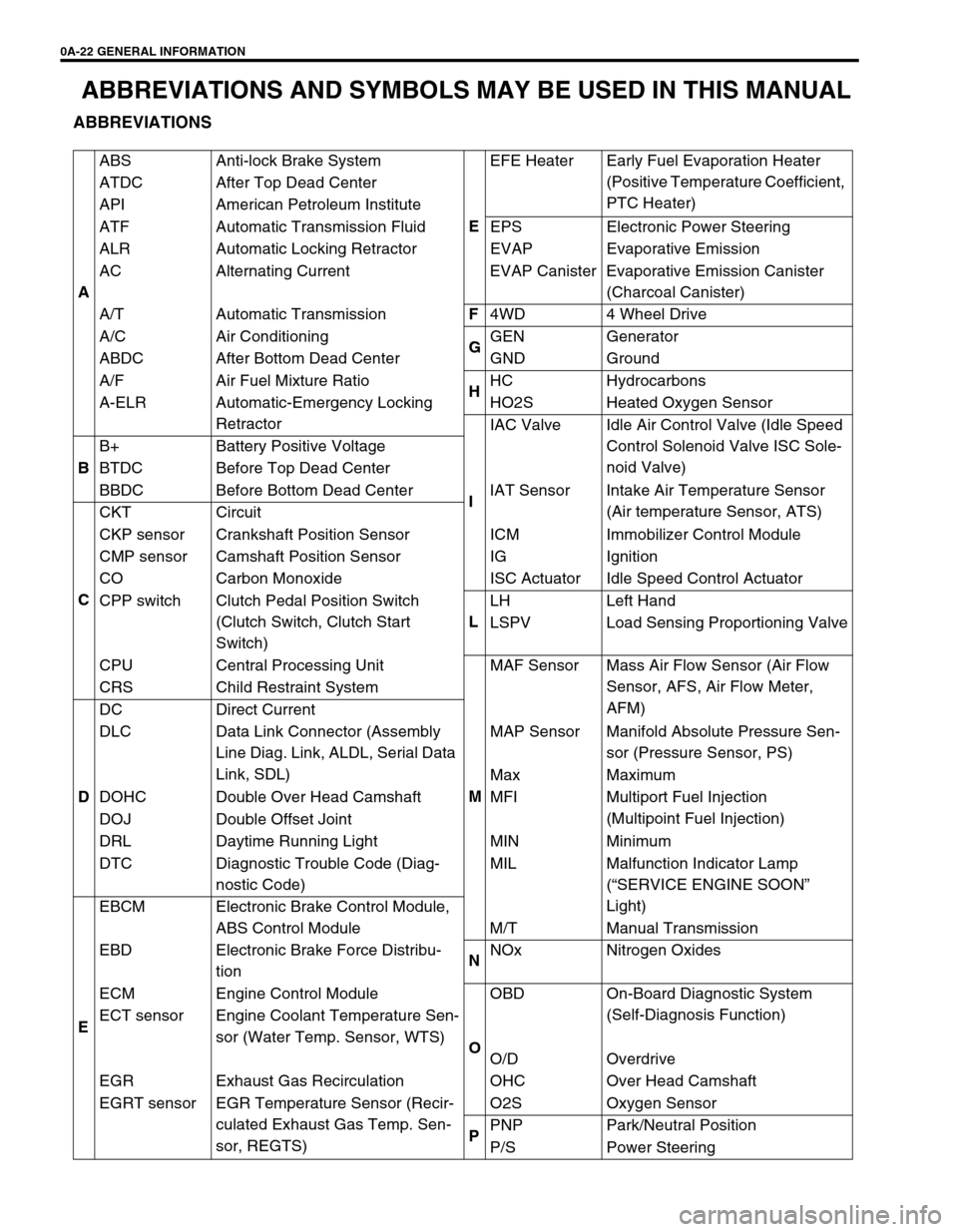
ABBREVIATIONS AND SYMBOLS MAY BE USED IN THIS MANUAL
ABBREVIATIONS
AABS Anti-lock Brake System
EEFE Heater Early Fuel Evaporation Heater
(Positive Temperature Coefficient,
PTC Heater) ATDC After Top Dead Center
API American Petroleum Institute
ATF Automatic Transmission Fluid EPS Electronic Power Steering
ALR Automatic Locking Retractor EVAP Evaporative Emission
AC Alternating Current EVAP Canister Evaporative Emission Canister
(Charcoal Canister)
A/T Automatic TransmissionF
4WD 4 Wheel Drive
A/C Air Conditioning
GGEN Generator
ABDC After Bottom Dead Center GND Ground
A/F Air Fuel Mixture Ratio
HHC Hydrocarbons
A-ELR Automatic-Emergency Locking
RetractorHO2S Heated Oxygen Sensor
IIAC Valve Idle Air Control Valve (Idle Speed
Control Solenoid Valve ISC Sole-
noid Valve)
BB+ Battery Positive Voltage
BTDC Before Top Dead Center
BBDC Before Bottom Dead Center IAT Sensor Intake Air Temperature Sensor
(Air temperature Sensor, ATS)
CCKT Circuit
CKP sensor Crankshaft Position Sensor ICM Immobilizer Control Module
CMP sensor Camshaft Position Sensor IG Ignition
CO Carbon Monoxide ISC Actuator Idle Speed Control Actuator
CPP switch Clutch Pedal Position Switch
(Clutch Switch, Clutch Start
Switch)LLH Left Hand
LSPV Load Sensing Proportioning Valve
CPU Central Processing Unit
MMAF Sensor Mass Air Flow Sensor (Air Flow
Sensor, AFS, Air Flow Meter,
AFM) CRS Child Restraint System
DDC Direct Current
DLC Data Link Connector (Assembly
Line Diag. Link, ALDL, Serial Data
Link, SDL)MAP Sensor Manifold Absolute Pressure Sen-
sor (Pressure Sensor, PS)
Max Maximum
DOHC Double Over Head Camshaft MFI Multiport Fuel Injection
(Multipoint Fuel Injection)
DOJ Double Offset Joint
DRL Daytime Running Light MIN Minimum
DTC Diagnostic Trouble Code (Diag-
nostic Code)MIL Malfunction Indicator Lamp
(“SERVICE ENGINE SOON”
Light)
EEBCM Electronic Brake Control Module,
ABS Control Module M/T Manual Transmission
EBD Electronic Brake Force Distribu-
tionNNOx Nitrogen Oxides
ECM Engine Control Module
OOBD On-Board Diagnostic System
(Self-Diagnosis Function)
ECT sensor Engine Coolant Temperature Sen-
sor (Water Temp. Sensor, WTS)
O/D Overdrive
EGR Exhaust Gas Recirculation OHC Over Head Camshaft
EGRT sensor EGR Temperature Sensor (Recir-
culated Exhaust Gas Temp. Sen-
sor, REGTS)O2S Oxygen Sensor
PPNP Park/Neutral Position
P/S Power Steering
Page 27 of 698
0A-24 GENERAL INFORMATION
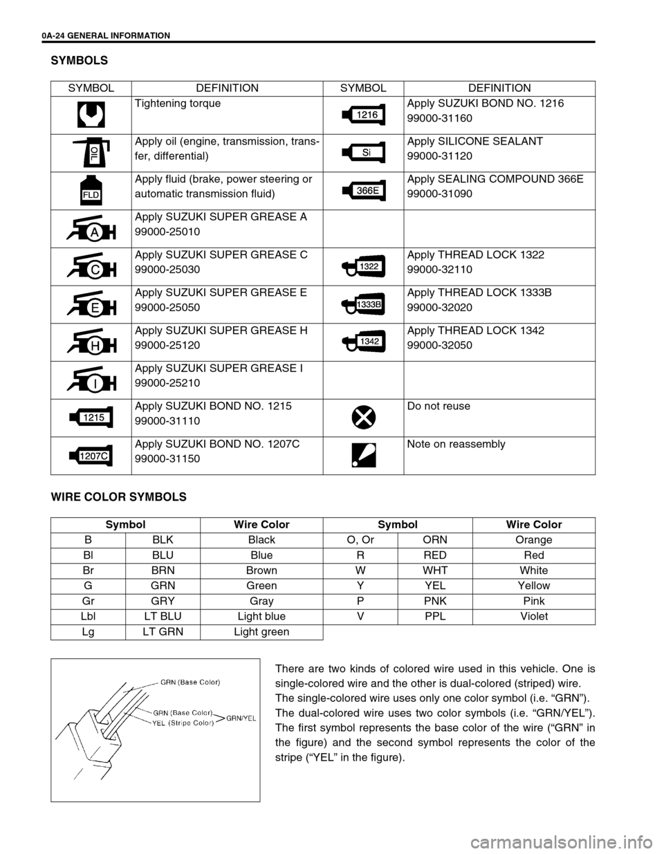
SYMBOLS
WIRE COLOR SYMBOLS
There are two kinds of colored wire used in this vehicle. One is
single-colored wire and the other is dual-colored (striped) wire.
The single-colored wire uses only one color symbol (i.e. “GRN”).
The dual-colored wire uses two color symbols (i.e. “GRN/YEL”).
The first symbol represents the base color of the wire (“GRN” in
the figure) and the second symbol represents the color of the
stripe (“YEL” in the figure). SYMBOL DEFINITION SYMBOL DEFINITION
Tightening torque Apply SUZUKI BOND NO. 1216
99000-31160
Apply oil (engine, transmission, trans-
fer, differential)Apply SILICONE SEALANT
99000-31120
Apply fluid (brake, power steering or
automatic transmission fluid)Apply SEALING COMPOUND 366E
99000-31090
Apply SUZUKI SUPER GREASE A
99000-25010
Apply SUZUKI SUPER GREASE C
99000-25030Apply THREAD LOCK 1322
99000-32110
Apply SUZUKI SUPER GREASE E
99000-25050Apply THREAD LOCK 1333B
99000-32020
Apply SUZUKI SUPER GREASE H
99000-25120Apply THREAD LOCK 1342
99000-32050
Apply SUZUKI SUPER GREASE I
99000-25210
Apply SUZUKI BOND NO. 1215
99000-31110Do not reuse
Apply SUZUKI BOND NO. 1207C
99000-31150Note on reassembly
Symbol Wire Color Symbol Wire Color
B BLK Black O, Or ORN Orange
Bl BLU Blue R RED Red
Br BRN Brown W WHT White
GGRN Green Y YEL Yellow
Gr GRY Gray P PNK Pink
Lbl LT BLU Light blue V PPL Violet
Lg LT GRN Light green
Page 50 of 698
MAINTENANCE AND LUBRICATION 0B-21
STEERING
Check to ensure that steering wheel is free from instability, or abnormally heavy feeling.
Check that the vehicle does not wander or pull to one side.
ENGINE
Check that engine responds readily at all speeds.
Check that engine is free from abnormal noise and abnormal vibration.
BODY, WHEELS AND POWER TRANSMITTING SYSTEM
Check that body, wheels and power transmitting system are free from abnormal noise and abnormal vibration or
any other abnormal condition.
METERS AND GAUGE
Check that speedometer, odometer, fuel meter, temperature gauge, etc. are operating accurately.
LIGHTS
Check that all lights operate properly.
WINDSHIELD DEFROSTER
Periodically check that air comes out from defroster outlet when operating heater or air conditioning.
Set mode control lever to defroster position and fan switch lever to “HI” position for this check.
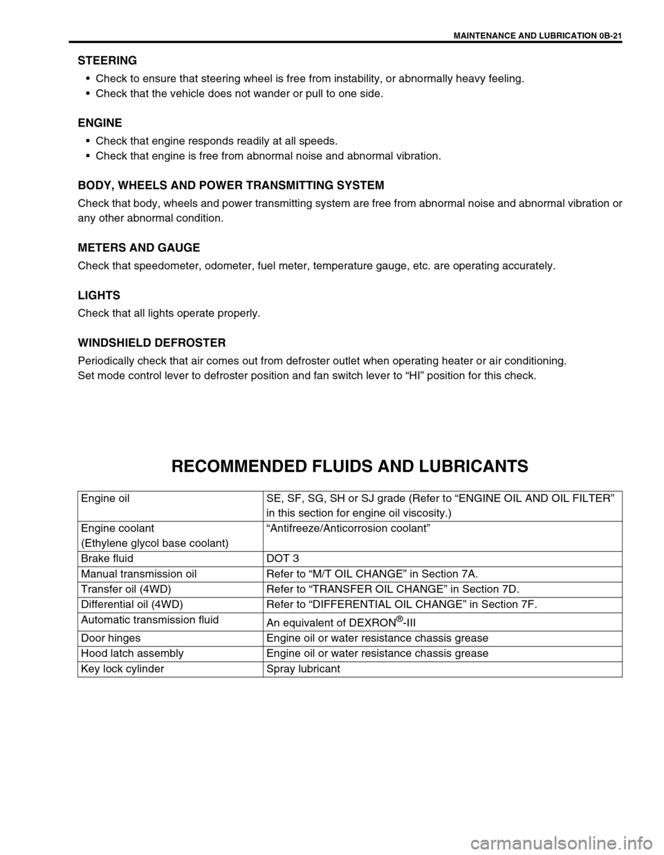
RECOMMENDED FLUIDS AND LUBRICANTS
Engine oil SE, SF, SG, SH or SJ grade (Refer to “ENGINE OIL AND OIL FILTER”
in this section for engine oil viscosity.)
Engine coolant
(Ethylene glycol base coolant)“Antifreeze/Anticorrosion coolant”
Brake fluid DOT 3
Manual transmission oil Refer to “M/T OIL CHANGE” in Section 7A.
Transfer oil (4WD) Refer to “TRANSFER OIL CHANGE” in Section 7D.
Differential oil (4WD) Refer to “DIFFERENTIAL OIL CHANGE” in Section 7F.
Automatic transmission fluid
An equivalent of DEXRON
®-III
Door hinges Engine oil or water resistance chassis grease
Hood latch assembly Engine oil or water resistance chassis grease
Key lock cylinder Spray lubricant
Page 290 of 698
BRAKES 5-17
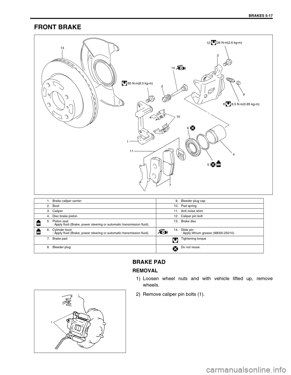
FRONT BRAKE
BRAKE PAD
REMOVAL
1) Loosen wheel nuts and with vehicle lifted up, remove
wheels.
2) Remove caliper pin bolts (1).
1. Brake caliper carrier 9. Bleeder plug cap
2. Boot 10. Pad spring
3. Caliper 11. Anti noise shim
4. Disc brake piston 12. Caliper pin bolt
5. Piston seal
: Apply fluid (Brake, power steering or automatic transmission fluid).13. Brake disc
6. Cylinder boot
: Apply fluid (Brake, power steering or automatic transmission fluid).14. Slide pin
: Apply lithium grease (99000-25010).
7. Brake pad Tightening torque
8. Bleeder plugDo not reuse.
9
1
7
13
2
143
1226 N·m(2.6 kg-m)
85 N·m(8.5 kg-m)
8
8.5 N·m(0.85 kg-m)
10
5 4
6
11
Page 328 of 698
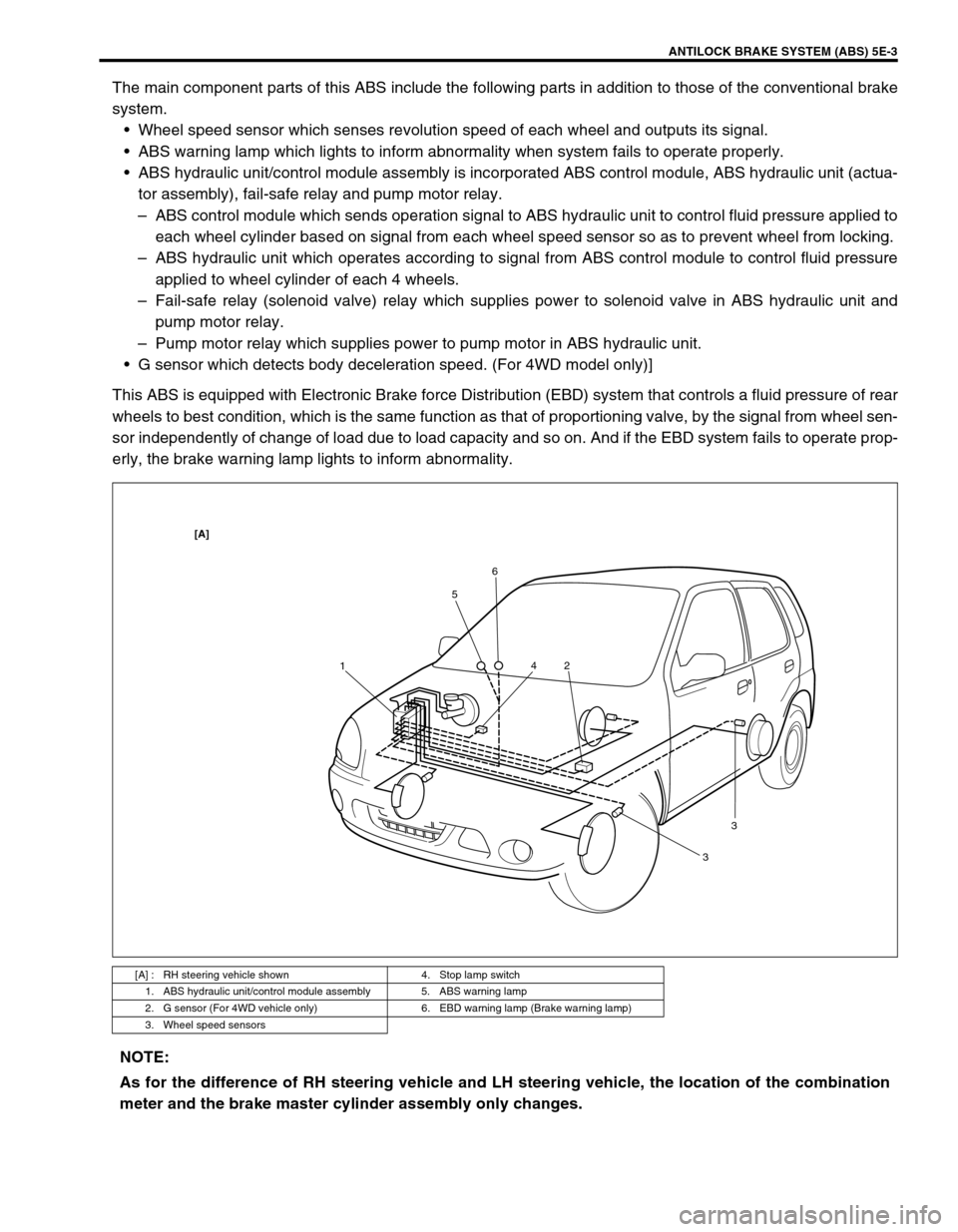
ANTILOCK BRAKE SYSTEM (ABS) 5E-3
The main component parts of this ABS include the following parts in addition to those of the conventional brake
system.
Wheel speed sensor which senses revolution speed of each wheel and outputs its signal.
ABS warning lamp which lights to inform abnormality when system fails to operate properly.
ABS hydraulic unit/control module assembly is incorporated ABS control module, ABS hydraulic unit (actua-
tor assembly), fail-safe relay and pump motor relay.
–ABS control module which sends operation signal to ABS hydraulic unit to control fluid pressure applied to
each wheel cylinder based on signal from each wheel speed sensor so as to prevent wheel from locking.
–ABS hydraulic unit which operates according to signal from ABS control module to control fluid pressure
applied to wheel cylinder of each 4 wheels.
–Fail-safe relay (solenoid valve) relay which supplies power to solenoid valve in ABS hydraulic unit and
pump motor relay.
–Pump motor relay which supplies power to pump motor in ABS hydraulic unit.
G sensor which detects body deceleration speed. (For 4WD model only)]
This ABS is equipped with Electronic Brake force Distribution (EBD) system that controls a fluid pressure of rear
wheels to best condition, which is the same function as that of proportioning valve, by the signal from wheel sen-
sor independently of change of load due to load capacity and so on. And if the EBD system fails to operate prop-
erly, the brake warning lamp lights to inform abnormality.
[A] : RH steering vehicle shown 4. Stop lamp switch
1. ABS hydraulic unit/control module assembly 5. ABS warning lamp
2. G sensor (For 4WD vehicle only) 6. EBD warning lamp (Brake warning lamp)
3. Wheel speed sensors
156
2 4
33
[A]
NOTE:
As for the difference of RH steering vehicle and LH steering vehicle, the location of the combination
meter and the brake master cylinder assembly only changes.