spare wheel SUZUKI SWIFT 2000 1.G RG413 Service Workshop Manual
[x] Cancel search | Manufacturer: SUZUKI, Model Year: 2000, Model line: SWIFT, Model: SUZUKI SWIFT 2000 1.GPages: 698, PDF Size: 16.01 MB
Page 256 of 698

FRONT DRIVE SHAFT 4A-3
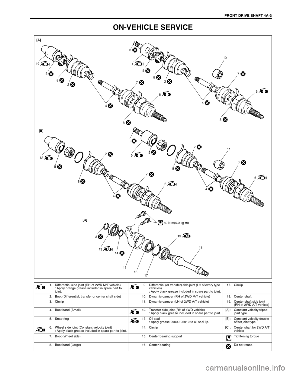
ON-VEHICLE SERVICE
1. Differential side joint (RH of 2WD M/T vehicle)
: Apply orange grease included in spare part to
joint.9. Differential (or transfer) side joint (LH of every type
vehicles)
: Apply black grease included in spare part to joint.17. Circlip
2. Boot (Differential, transfer or center shaft side) 10. Dynamic damper (RH of 2WD M/T vehicle) 18. Center shaft
3. Circlip 11. Dynamic damper (LH of 2WD A/T vehicle) 19. Center shaft side joint
(RH of 2WD A/T vehicle)
4. Boot band (Small) 12. Transfer side joint (RH of 4WD vehicle)
: Apply black grease included in spare part to joint.[A] : Constant velocity tripod
joint type
5. Snap ring 13. Oil seal
: Apply grease 99000-25010 to oil seal lip.[B] : Constant velocity double
offset joint type
6. Wheel side joint (Constant velocity joint)
: Apply black grease included in spare part to joint.14. Circlip [C] : Center shaft for 2WD A/T
vehicle
7. Boot (Wheel side) 15. Center bearing support Tightening torque
8. Boot band (Large) 16. Center bearing Do not reuse.
Page 262 of 698

FRONT DRIVE SHAFT 4A-9
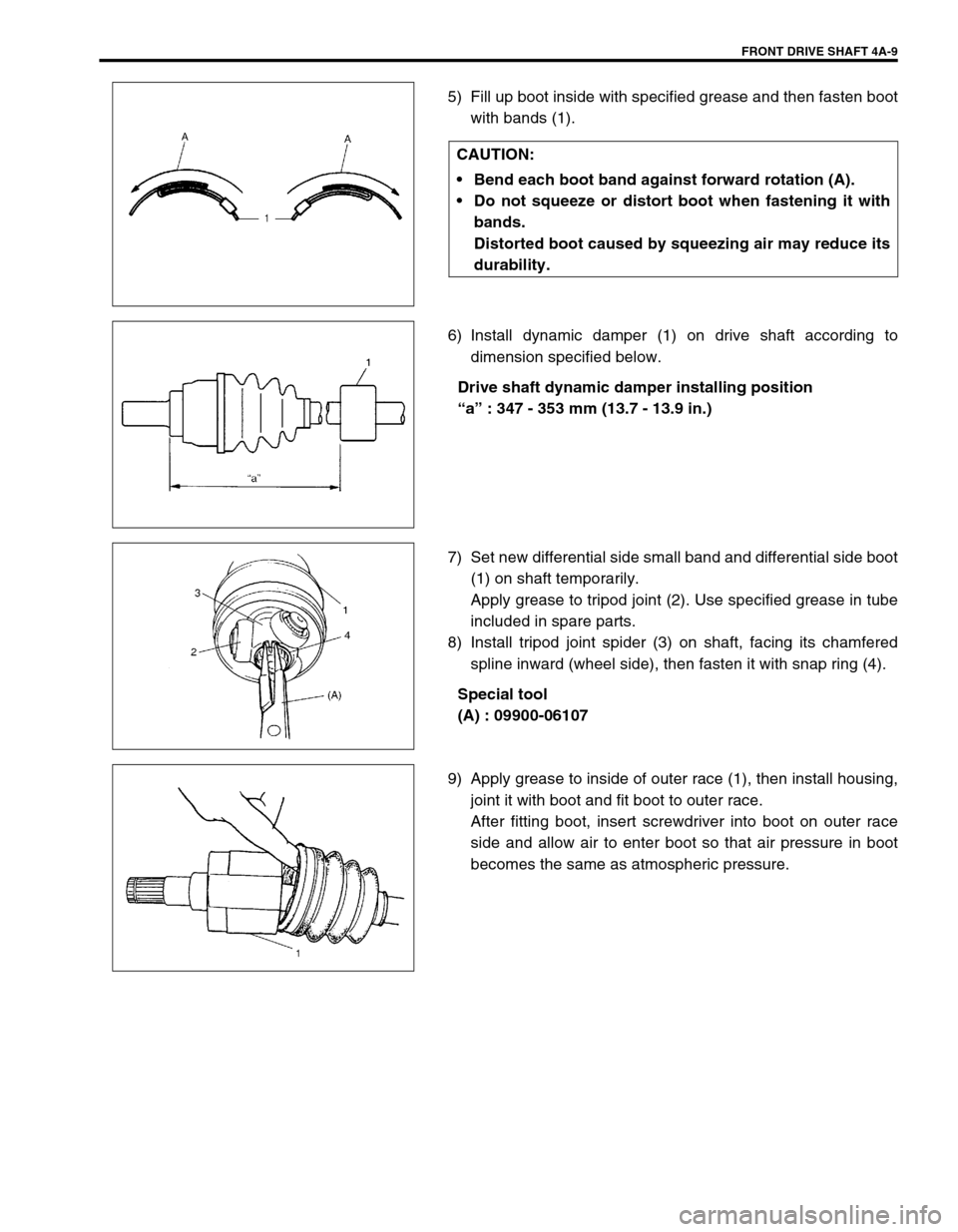
5) Fill up boot inside with specified grease and then fasten boot
with bands (1).
6) Install dynamic damper (1) on drive shaft according to
dimension specified below.
Drive shaft dynamic damper installing position
“a” : 347 - 353 mm (13.7 - 13.9 in.)
7) Set new differential side small band and differential side boot
(1) on shaft temporarily.
Apply grease to tripod joint (2). Use specified grease in tube
included in spare parts.
8) Install tripod joint spider (3) on shaft, facing its chamfered
spline inward (wheel side), then fasten it with snap ring (4).
Special tool
(A) : 09900-06107
9) Apply grease to inside of outer race (1), then install housing,
joint it with boot and fit boot to outer race.
After fitting boot, insert screwdriver into boot on outer race
side and allow air to enter boot so that air pressure in boot
becomes the same as atmospheric pressure. CAUTION:
Bend each boot band against forward rotation (A).
Do not squeeze or distort boot when fastening it with
bands.
Distorted boot caused by squeezing air may reduce its
durability.
Page 265 of 698

4A-12 FRONT DRIVE SHAFT
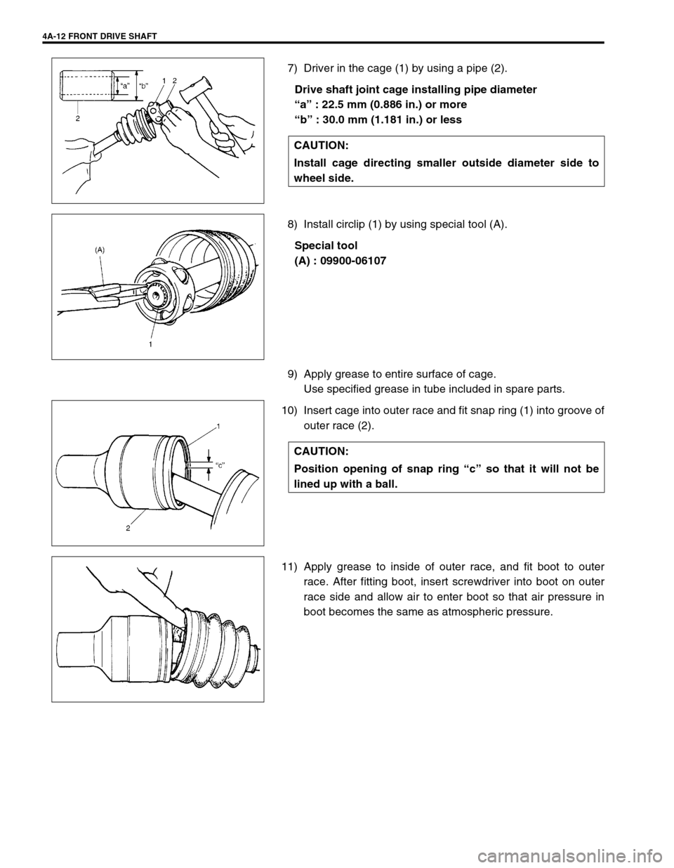
7) Driver in the cage (1) by using a pipe (2).
Drive shaft joint cage installing pipe diameter
“a” : 22.5 mm (0.886 in.) or more
“b” : 30.0 mm (1.181 in.) or less
8) Install circlip (1) by using special tool (A).
Special tool
(A) : 09900-06107
9) Apply grease to entire surface of cage.
Use specified grease in tube included in spare parts.
10) Insert cage into outer race and fit snap ring (1) into groove of
outer race (2).
11) Apply grease to inside of outer race, and fit boot to outer
race. After fitting boot, insert screwdriver into boot on outer
race side and allow air to enter boot so that air pressure in
boot becomes the same as atmospheric pressure. CAUTION:
Install cage directing smaller outside diameter side to
wheel side.
CAUTION:
Position opening of snap ring “c” so that it will not be
lined up with a ball.
Page 286 of 698

BRAKES 5-13
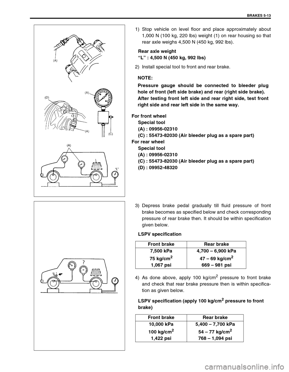
1) Stop vehicle on level floor and place approximately about
1,000 N (100 kg, 220 lbs) weight (1) on rear housing so that
rear axle weighs 4,500 N (450 kg, 992 lbs).
Rear axle weight
“L” : 4,500 N (450 kg, 992 lbs)
2) Install special tool to front and rear brake.
For front wheel
Special tool
(A) : 09956-02310
(C) : 55473-82030 (Air bleeder plug as a spare part)
For rear wheel
Special tool
(A) : 09956-02310
(C) : 55473-82030 (Air bleeder plug as a spare part)
(D) : 09952-48320
3) Depress brake pedal gradually till fluid pressure of front
brake becomes as specified below and check corresponding
pressure of rear brake then. It should be within specification
given below.
LSPV specification
4) As done above, apply 100 kg/cm
2 pressure to front brake
and check that rear brake pressure then is within specifica-
tion as given below.
LSPV specification (apply 100 kg/cm
2 pressure to front
brake) NOTE:
Pressure gauge should be connected to bleeder plug
hole of front (left side brake) and rear (right side brake).
After testing front left side and rear right side, test front
right side and rear left side in the same way.
Front brake Rear brake
7,500 kPa
75 kg/cm
2
1,067 psi4,700 – 6,900 kPa
47 – 69 kg/cm
2
669 – 981 psi
Front brake Rear brake
10,000 kPa
100 kg/cm
2
1,422 psi5,400 – 7,700 kPa
54 – 77 kg/cm
2
768 – 1,094 psi