fuel cap release SUZUKI SWIFT 2000 1.G RG413 Service Workshop Manual
[x] Cancel search | Manufacturer: SUZUKI, Model Year: 2000, Model line: SWIFT, Model: SUZUKI SWIFT 2000 1.GPages: 698, PDF Size: 16.01 MB
Page 375 of 698

6-6 ENGINE GENERAL INFORMATION AND DIAGNOSIS
FUEL PRESSURE RELIEF PROCEDURE
After making sure that engine is cold, release fuel pressure as fol-
lows.
1) Place transmission gear shift lever in “Neutral” (Shift selector
lever to “P” range for A/T model), set parking brake, and
block drive wheels.
2) Remove relay box cover.
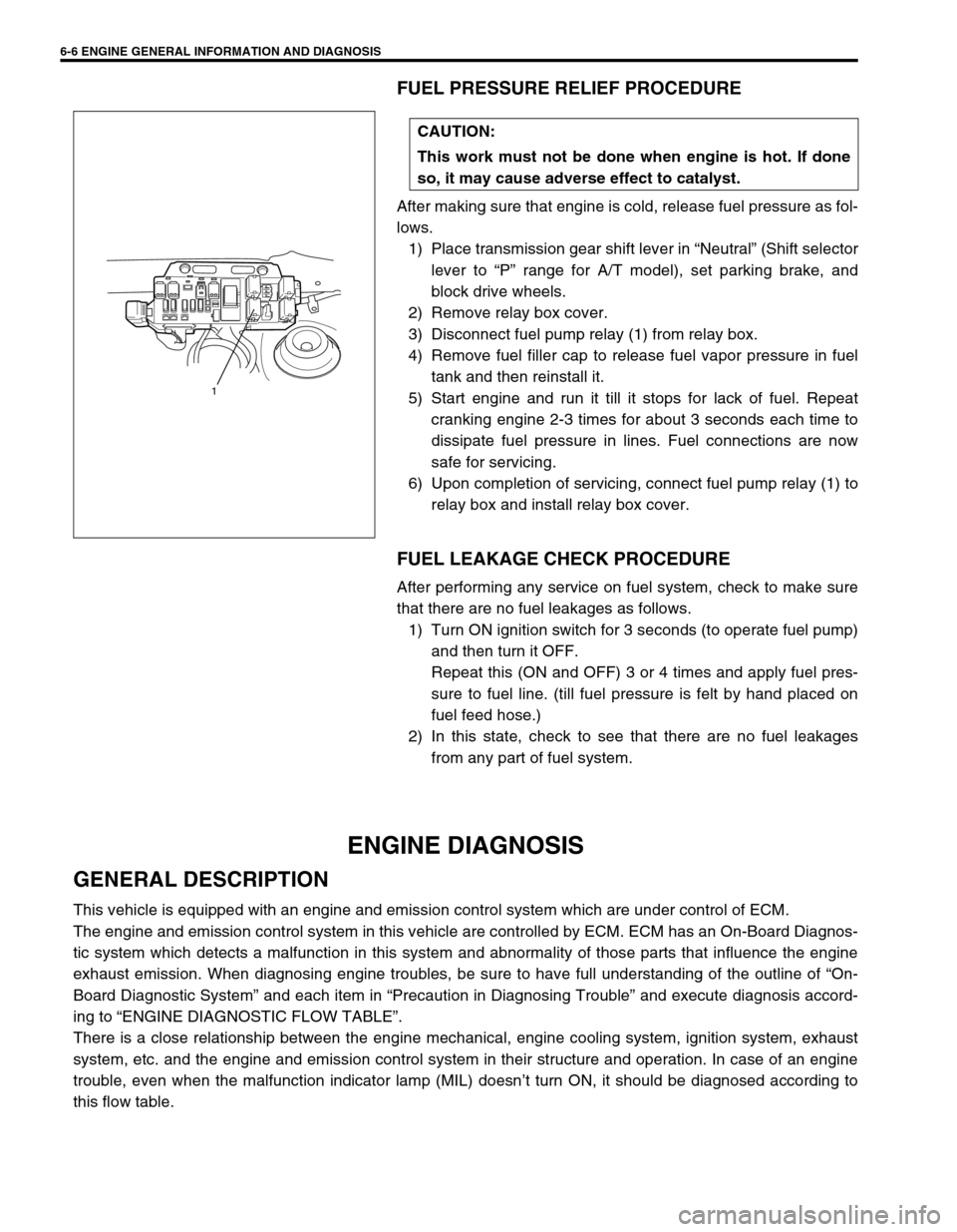
3) Disconnect fuel pump relay (1) from relay box.
4) Remove fuel filler cap to release fuel vapor pressure in fuel
tank and then reinstall it.
5) Start engine and run it till it stops for lack of fuel. Repeat
cranking engine 2-3 times for about 3 seconds each time to
dissipate fuel pressure in lines. Fuel connections are now
safe for servicing.
6) Upon completion of servicing, connect fuel pump relay (1) to
relay box and install relay box cover.
FUEL LEAKAGE CHECK PROCEDURE
After performing any service on fuel system, check to make sure
that there are no fuel leakages as follows.
1) Turn ON ignition switch for 3 seconds (to operate fuel pump)
and then turn it OFF.
Repeat this (ON and OFF) 3 or 4 times and apply fuel pres-
sure to fuel line. (till fuel pressure is felt by hand placed on
fuel feed hose.)
2) In this state, check to see that there are no fuel leakages
from any part of fuel system.
ENGINE DIAGNOSIS
GENERAL DESCRIPTION
This vehicle is equipped with an engine and emission control system which are under control of ECM.
The engine and emission control system in this vehicle are controlled by ECM. ECM has an On-Board Diagnos-
tic system which detects a malfunction in this system and abnormality of those parts that influence the engine
exhaust emission. When diagnosing engine troubles, be sure to have full understanding of the outline of “On-
Board Diagnostic System” and each item in “Precaution in Diagnosing Trouble” and execute diagnosis accord-
ing to “ENGINE DIAGNOSTIC FLOW TABLE”.
There is a close relationship between the engine mechanical, engine cooling system, ignition system, exhaust
system, etc. and the engine and emission control system in their structure and operation. In case of an engine
trouble, even when the malfunction indicator lamp (MIL) doesn’t turn ON, it should be diagnosed according to
this flow table.CAUTION:
This work must not be done when engine is hot. If done
so, it may cause adverse effect to catalyst.
1
Page 610 of 698

ENGINE FUEL 6C-3
PRECAUTIONS
WARNING:
Before attempting service of any type on fuel system, the
followings should be always observed in order to reduce
the risk or fire and personal injury.
Disconnect negative cable at battery.
Do not smoke, and place no smoking signs near work
area.
Be sure to have CO
2 fire extinguisher handy.
Be sure to perform work in a well-ventilated area and
away from any open flames (such as gas hot heater).
Wear safety glasses.
To relieve fuel vapor pressure in fuel tank, remove fuel
filler cap from fuel filler neck and then reinstall it.
As fuel feed line is still under high fuel pressure even
after engine was stopped, loosening or disconnecting
fuel feed line directly may cause dangerous spout of
fuel to occur where loosened or disconnected.
Before loosening or disconnecting fuel feed line, make
sure to relieve fuel pressure “FUEL PRESSURE
RELIEF PROCEDURE” in Section 6.
A small amount of fuel may be released after the fuel
line is disconnected. In order to reduce the chance of
personal injury, cover the fitting to be disconnected
with a shop cloth. Be sure to put that cloth in an
approved container when disconnection is completed.
Note that fuel hose connection varies with each type of
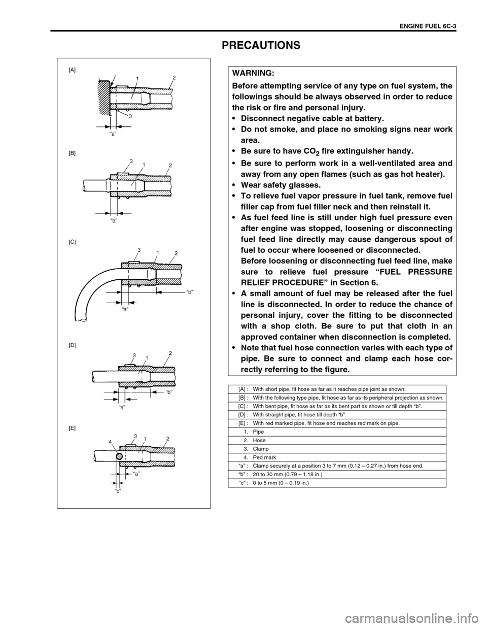
pipe. Be sure to connect and clamp each hose cor-
rectly referring to the figure.
[A] : With short pipe, fit hose as far as it reaches pipe joint as shown.
[B] : With the following type pipe, fit hose as far as its peripheral projection as shown.
[C] : With bent pipe, fit hose as far as its bent part as shown or till depth “b”.
[D] : With straight pipe, fit hose till depth “b”.
[E] : With red marked pipe, fit hose end reaches red mark on pipe.
1. Pipe
2. Hose
3. Clamp
4. Ped mark
“a” : Clamp securely at a position 3 to 7 mm (0.12 – 0.27 in.) from hose end.
“b” : 20 to 30 mm (0.79 – 1.18 in.)
“c” : 0 to 5 mm (0 – 0.19 in.)
Page 643 of 698

6E1-22 ENGINE AND EMISSION CONTROL SYSTEM
6) Start engine and warm it up to normal operating tempera-
ture.
7) Measure fuel pressure at idling.
If measured pressure does not satisfy specification, refer to
“Diagnostic Flow Table B-3” in “Engine Diagnosis” section
and check each possibly defective part. Replace if found
defective.
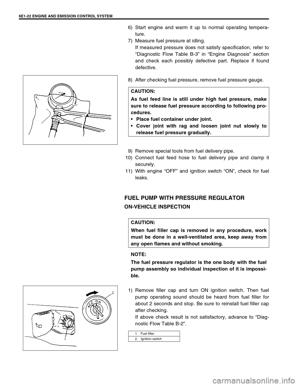
8) After checking fuel pressure, remove fuel pressure gauge.
9) Remove special tools from fuel delivery pipe.
10) Connect fuel feed hose to fuel delivery pipe and clamp it
securely.
11) With engine “OFF” and ignition switch “ON”, check for fuel
leaks.
FUEL PUMP WITH PRESSURE REGULATOR
ON-VEHICLE INSPECTION
1) Remove filler cap and turn ON ignition switch. Then fuel
pump operating sound should be heard from fuel filler for
about 2 seconds and stop. Be sure to reinstall fuel filler cap
after checking.
If above check result is not satisfactory, advance to “Diag-
nostic Flow Table B-2”. CAUTION:
As fuel feed line is still under high fuel pressure, make
sure to release fuel pressure according to following pro-
cedures.
Place fuel container under joint.
Cover joint with rag and loosen joint nut slowly to
release fuel pressure gradually.
CAUTION:
When fuel filler cap is removed in any procedure, work
must be done in a well-ventilated area, keep away from
any open flames and without smoking.
NOTE:
The fuel pressure regulator is the one body with the fuel
pump assembly so individual inspection of it is impossi-
ble.
1. Fuel filler
2. Ignition switch