battery SUZUKI SWIFT 2000 1.G Transmission Service User Guide
[x] Cancel search | Manufacturer: SUZUKI, Model Year: 2000, Model line: SWIFT, Model: SUZUKI SWIFT 2000 1.GPages: 447, PDF Size: 10.54 MB
Page 95 of 447

AUTOMATIC TRANSMISSION (4 A/T) 7B-53
INSPECTION OF TCM AND ITS CIRCUITS
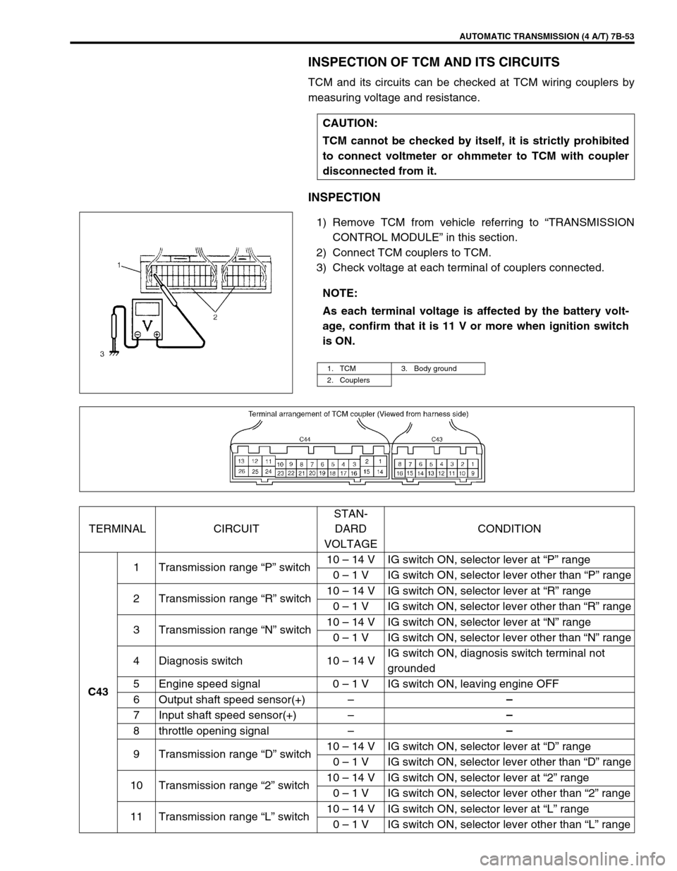
TCM and its circuits can be checked at TCM wiring couplers by
measuring voltage and resistance.
INSPECTION
1) Remove TCM from vehicle referring to “TRANSMISSION
CONTROL MODULE” in this section.
2) Connect TCM couplers to TCM.
3) Check voltage at each terminal of couplers connected.CAUTION:
TCM cannot be checked by itself, it is strictly prohibited
to connect voltmeter or ohmmeter to TCM with coupler
disconnected from it.
NOTE:
As each terminal voltage is affected by the battery volt-
age, confirm that it is 11 V or more when ignition switch
is ON.
1. TCM 3. Body ground
2. Couplers
TERMINAL CIRCUITSTAN-
DARD
VOLTAGECONDITION
C431 Transmission range “P” switch10 – 14 V IG switch ON, selector lever at “P” range
0 – 1 V IG switch ON, selector lever other than “P” range
2 Transmission range “R” switch10 – 14 V IG switch ON, selector lever at “R” range
0 – 1 V IG switch ON, selector lever other than “R” range
3 Transmission range “N” switch10 – 14 V IG switch ON, selector lever at “N” range
0 – 1 V IG switch ON, selector lever other than “N” range
4 Diagnosis switch 10 – 14 VIG switch ON, diagnosis switch terminal not
grounded
5 Engine speed signal 0 – 1 V IG switch ON, leaving engine OFF
6 Output shaft speed sensor(+)––
7 Input shaft speed sensor(+)––
8 throttle opening signal––
9 Transmission range “D” switch10 – 14 V IG switch ON, selector lever at “D” range
0 – 1 V IG switch ON, selector lever other than “D” range
10 Transmission range “2” switch10 – 14 V IG switch ON, selector lever at “2” range
0 – 1 V IG switch ON, selector lever other than “2” range
11 Transmission range “L” switch10 – 14 V IG switch ON, selector lever at “L” range
0 – 1 V IG switch ON, selector lever other than “L” range
Page 104 of 447

7B-62 AUTOMATIC TRANSMISSION (4 A/T)
OUTPUT SHAFT SPEED SENSOR (A/T VSS)
INSPECTION
1) Disconnect negative cable at battery.
2) Disconnect output shaft speed sensor – input shaft speed
sensor coupler (1).
3) Check resistance between output shaft speed sensor termi-
nals (2).
Output shaft speed sensor resistance
Standard : 160 – 200
Ω
ΩΩ Ω at 20°C (68°F)
REMOVAL
1) Disconnect negative cable at battery.
2) Disconnect output shaft speed sensor – input shaft speed
sensor coupler.
3) Remove output shaft speed sensor (1) by removing its bolt.
INSTALLATION
1) Apply A/T fluid to output shaft speed sensor o-ring.
2) Install output shaft speed sensor (1) to A/T case and tighten
bolt to specified torque.
Tightening torque
Output shaft speed sensor bolt
(a) : 8 N·m (0.8 kg-m, 6.0 lb-ft)
3) Connect output shaft speed sensor – input shaft speed sen-
sor coupler.
4) Connect negative cable to battery.
Page 105 of 447

AUTOMATIC TRANSMISSION (4 A/T) 7B-63
INPUT SHAFT SPEED SENSOR
INSPECTION
1) Disconnect negative cable at battery.
2) Disconnect output shaft speed sensor – input shaft speed
sensor coupler (1).
3) Check resistance between input shaft speed sensor termi-
nals (2).
Input shaft speed sensor resistance
Standard : 160 – 200
Ω
ΩΩ Ω at 20°C (68°F)
REMOVAL
1) Disconnect negative cable at battery.
2) Disconnect output shaft speed sensor – input shaft speed
sensor coupler.
3) Remove input shaft speed sensor (1) by removing its bolt.
INSTALLATION
1) Apply A/T fluid to input shaft speed sensor O-ring.
2) Install input shaft speed sensor (1) to A/T case and tighten
bolt to specified torque.
Tightening torque
Input shaft speed sensor bolt
(b) : 8 N·m (0.8 kg-m, 6.0 lb-ft)
3) Connect output shaft speed sensor – input shaft speed sen-
sor coupler.
4) Connect negative cable to battery.
VEHICLE SPEED SENSOR (VSS)
Refer to Section 6E for removal, installation and inspection.
THROTTLE POSITION SENSOR
INSPECTION
Check throttle position sensor referring to Section 6E.
Page 107 of 447

AUTOMATIC TRANSMISSION (4 A/T) 7B-65
O/D OFF SWITCH
INSPECTION
1) Remove console box.
2) Disconnect O/D off switch coupler (1).
3) Check continuity between O/D off switch terminals.
O/D OFF switch specification
SHIFT SOLENOID VALVES AND TRANSMIS-
SION TEMPERATURE SENSOR
REMOVAL
1) Disconnect negative cable at battery.
2) Drain A/T fluid.
3) Remove A/T oil pan (1).
4) Disconnect transmission temp. sensor coupler (3).
5) Remove A/T oil strainer (2) and transmission temp. sensor
(1). O/D off switch ON OFF
Continuity Continuity No continuity
2. O/D off switch ON
3. O/D off switch OFF
Page 108 of 447

7B-66 AUTOMATIC TRANSMISSION (4 A/T)
6) Disconnect shift solenoid couplers.
7) Remove shift solenoid valves.
SHIFT SOLENOID VALVES
INSPECTION
Resistance Check
Shift solenoid A (No.1), B (No.2) and lock-up solenoid
Resistance between terminal and solenoid body
Standard : 10.5 – 15.5
Ω
ΩΩ Ω
Shift solenoid C (No.3), D (No.4) or E (No.5)
Resistance between terminal and solenoid body
Standard : 2.5 – 3.5
Ω
ΩΩ Ω
Operation check
When solenoids is connected to the battery as shown in figure,
check that the solenoid actuates with a click sound.
TRANSMISSION TEMPERATURE SENSOR
INSPECTION
Warm up transmission temp. sensor. Thus make sure its resis-
tance decrease with the increase of temperature.
Transmission temperature sensor resistance
1. Solenoid valve
1. Solenoid valve
Temperature Resistance
20°C (68°F) 2.5 k
Ω
ΩΩ Ω
40°C (104°F) 1.2 k
Ω
ΩΩ Ω
60°C (140°F) 0.6 k
Ω
ΩΩ Ω
1. Transmission temperature sensor coupler
Page 111 of 447

AUTOMATIC TRANSMISSION (4 A/T) 7B-69
TRANSMISSION CONTROL MODULE (TCM)
REMOVAL
1) Disconnect negative cable at battery.
2) If the vehicle is equipped with air bag system, disable air bag
system. Refer to “DISABLING AIR BAG SYSTEM” in Sec-
tion 10B.
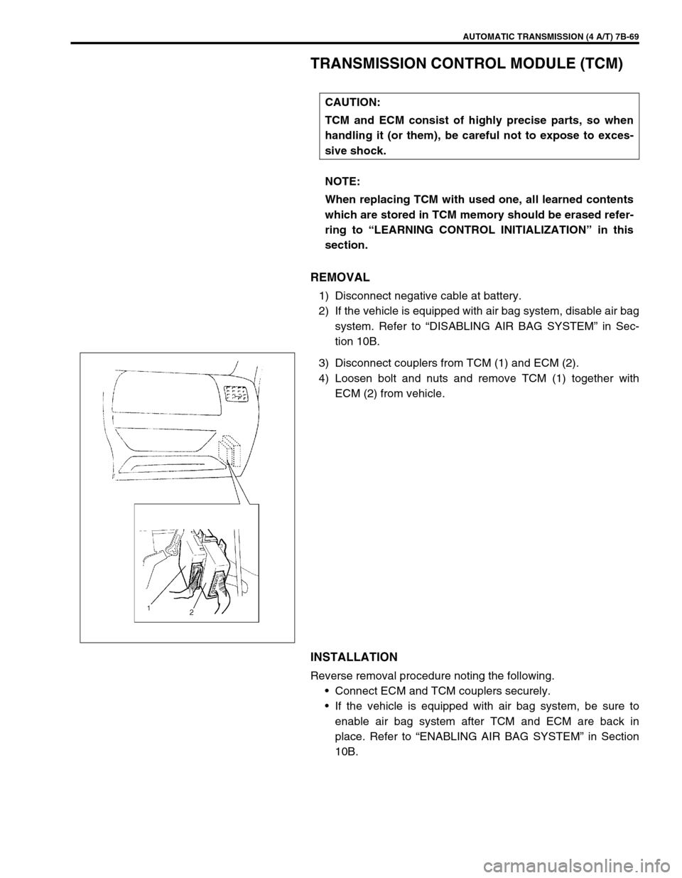
3) Disconnect couplers from TCM (1) and ECM (2).
4) Loosen bolt and nuts and remove TCM (1) together with
ECM (2) from vehicle.
INSTALLATION
Reverse removal procedure noting the following.
Connect ECM and TCM couplers securely.
If the vehicle is equipped with air bag system, be sure to
enable air bag system after TCM and ECM are back in
place. Refer to “ENABLING AIR BAG SYSTEM” in Section
10B. CAUTION:
TCM and ECM consist of highly precise parts, so when
handling it (or them), be careful not to expose to exces-
sive shock.
NOTE:
When replacing TCM with used one, all learned contents
which are stored in TCM memory should be erased refer-
ring to “LEARNING CONTROL INITIALIZATION” in this
section.
Page 115 of 447

AUTOMATIC TRANSMISSION (4 A/T) 7B-73
REMOVAL
1) Disconnect negative cable at battery and disable air bag sys-
tem, referring to “DISABLING AIR BAG SYSTEMS” in Sec-
tion 10B (if equipped).
2) Remove steering column hole cover and steering column
cover.
3) Remove steering column mounting bolts and nuts.
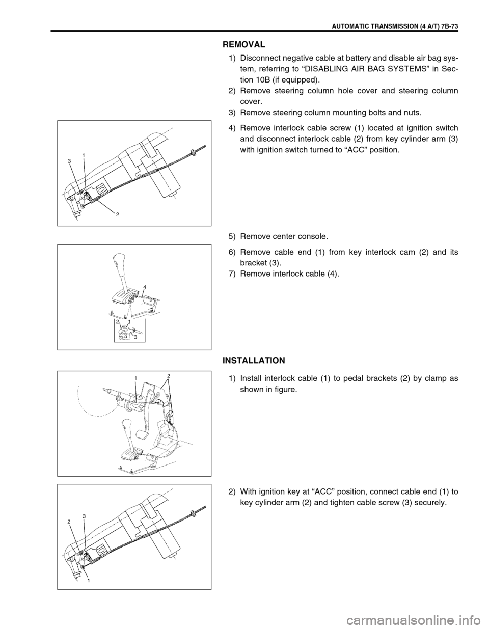
4) Remove interlock cable screw (1) located at ignition switch
and disconnect interlock cable (2) from key cylinder arm (3)
with ignition switch turned to “ACC” position.
5) Remove center console.
6) Remove cable end (1) from key interlock cam (2) and its
bracket (3).
7) Remove interlock cable (4).
INSTALLATION
1) Install interlock cable (1) to pedal brackets (2) by clamp as
shown in figure.
2) With ignition key at “ACC” position, connect cable end (1) to
key cylinder arm (2) and tighten cable screw (3) securely.
Page 116 of 447

7B-74 AUTOMATIC TRANSMISSION (4 A/T)
3) If selector lever is in “P” range, shift selector lever to other
than “P” range with releasing shift lock referring to “SHIFT
LOCK SOLENOID MANUAL RELEASE” in this section.
4) Install cable end (1) and cable casing cap (2) to key interlock
cam (3) and its bracket (4), then install cable (5) to selector
pad (6).
5) With selector lever set at “P” position, turn ignition key to
“ACC” position and then check for following conditions.
With knob button released, ignition key can be turned from
“ACC” position to “LOCK” position.
With knob button pressed, ignition key cannot be turned from
“ACC” position to “LOCK” position.
6) Install steering column referring to Section 3C.
7) Install steering column hole cover.
8) Install center console.
9) Connect negative cable at battery and enable air bag sys-
tem, referring to “ENABLING AIR BAG SYSTEM” in Section
10B (if equipped).
Page 120 of 447

7B-78 AUTOMATIC TRANSMISSION (4 A/T)
UNIT DISASSEMBLY
1) Remove torque converter (1).
2) Remove engine mounting LH bracket.
3) Remove oil cooler (1) and battery ground cable (2) (if still
attached). CAUTION:
Thoroughly clean transmission exterior before over-
hauling it.
Keep working table, tools and hands clean while over-
hauling.
Use special care to handle aluminum parts so as not to
damage them.
Do not expose removed parts to dust. Keep them
always clean.
Page 183 of 447

CLUTCH 7C-1
6F1
6F2
6G
6H
6K
7A1
7B1
7C1
7D
7E
7C
8A
8B
8C
8D
8E
9
10
10A
10B
SECTION 7C
CLUTCH
CONTENTS
GENERAL DESCRIPTION .............................. 7C-2
DIAGNOSIS ..................................................... 7C-3
ON-VEHICLE SERVICE .................................. 7C-4
CLUTCH CABLE .......................................... 7C-4
CLUTCH PEDAL AND CLUTCH PEDAL
BRACKET .................................................... 7C-6
CLUTCH PEDAL HEIGHT ....................... 7C-7
CLUTCH PEDAL FREE TRAVEL ............ 7C-7UNIT REPAIR OVERHAUL ............................. 7C-8
CLUTCH COVER, CLUTCH DISC AND
FLYWHEEL.................................................. 7C-8
CLUTCH RELEASE SYSTEM ................... 7C-11
TIGHTENING TORQUE SPECIFICATION.... 7C-14
REQUIRED SERVICE MATERIAL................ 7C-14
SPECIAL TOOL ............................................ 7C-14
WARNING:
For vehicles equipped with Supplemental Restraint (Air Bag) System:
Service on and around the air bag system components or wiring must be performed only by an
authorized SUZUKI dealer. Refer to “Air Bag System Components and Wiring Location View” under
“General Description” in air bag system section in order to confirm whether you are performing ser-
vice on or near the air bag system components or wiring. Please observe all WARNINGS and “Ser-
vice Precautions” under “On-Vehicle Service” in air bag system section before performing service
on or around the air bag system components or wiring. Failure to follow WARNINGS could result in
unintentional activation of the system or could render the system inoperative. Either of these two
conditions may result in severe injury.
Technical service work must be started at least 90 seconds after the ignition switch is turned to the
“LOCK” position and the negative cable is disconnected from the battery. Otherwise, the system
may be activated by reserve energy in the Sensing and Diagnostic Module (SDM).