battery SUZUKI SWIFT 2000 1.G Transmission Service Repair Manual
[x] Cancel search | Manufacturer: SUZUKI, Model Year: 2000, Model line: SWIFT, Model: SUZUKI SWIFT 2000 1.GPages: 447, PDF Size: 10.54 MB
Page 430 of 447

10B-56 AIR BAG SYSTEM
SDM
REMOVAL
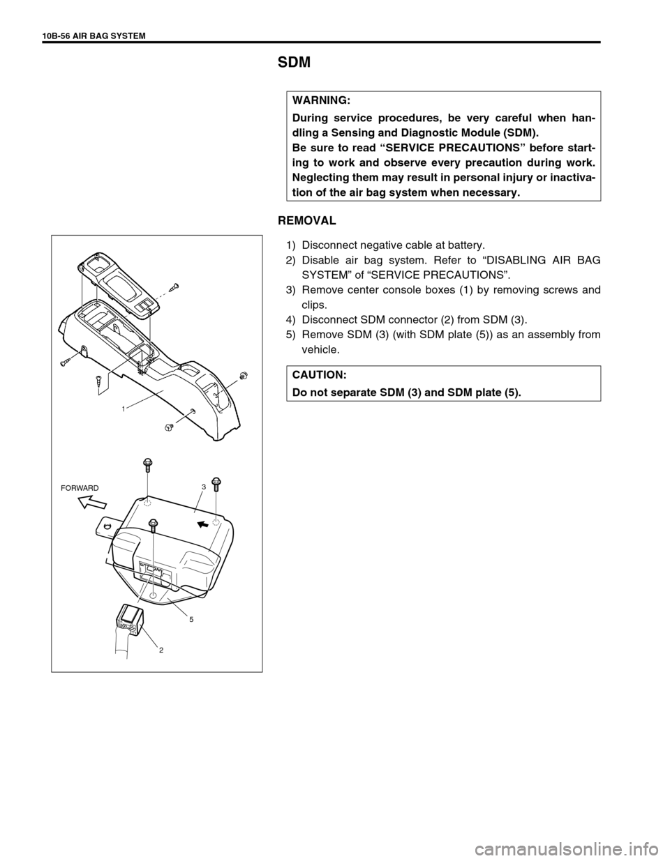
1) Disconnect negative cable at battery.
2) Disable air bag system. Refer to “DISABLING AIR BAG
SYSTEM” of “SERVICE PRECAUTIONS”.
3) Remove center console boxes (1) by removing screws and
clips.
4) Disconnect SDM connector (2) from SDM (3).
5) Remove SDM (3) (with SDM plate (5)) as an assembly from
vehicle. WARNING:
During service procedures, be very careful when han-
dling a Sensing and Diagnostic Module (SDM).
Be sure to read “SERVICE PRECAUTIONS” before start-
ing to work and observe every precaution during work.
Neglecting them may result in personal injury or inactiva-
tion of the air bag system when necessary.
CAUTION:
Do not separate SDM (3) and SDM plate (5).
3
5
2 FORWARD
Page 432 of 447

10B-58 AIR BAG SYSTEM
PASSENGER AIR BAG (INFLATOR) MODULE (IF EQUIPPED)
REMOVAL
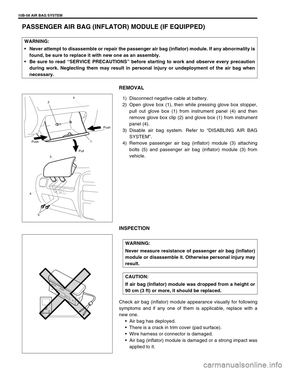
1) Disconnect negative cable at battery.
2) Open glove box (1), then while pressing glove box stopper,
pull out glove box (1) from instrument panel (4) and then
remove glove box clip (2) and glove box (1) from instrument
panel (4).
3) Disable air bag system. Refer to “DISABLING AIR BAG
SYSTEM”.
4) Remove passenger air bag (inflator) module (3) attaching
bolts (5) and passenger air bag (inflator) module (3) from
vehicle.
INSPECTION
Check air bag (inflator) module appearance visually for following
symptoms and if any one of them is applicable, replace with a
new one.
Air bag has deployed.
There is a crack in trim cover (pad surface).
Wire harness or connector is damaged.
Air bag (inflator) module is damaged or a strong impact was
applied to it. WARNING:
Never attempt to disassemble or repair the passenger air bag (inflator) module. If any abnormality is
found, be sure to replace it with new one as an assembly.
Be sure to read “SERVICE PRECAUTIONS” before starting to work and observe every precaution
during work. Neglecting them may result in personal injury or undeployment of the air bag when
necessary.
1 24
Push
Pull Push
3
4
5
WARNING:
Never measure resistance of passenger air bag (inflator)
module or disassemble it. Otherwise personal injury may
result.
CAUTION:
If air bag (Inflator) module was dropped from a height or
90 cm (3 ft) or more, it should be replaced.
Page 433 of 447

AIR BAG SYSTEM 10B-59
INSTALLATION
1) Install passenger air bag (inflator) module (1) to instrument
panel (2).
2) Tighten passenger air bag (inflator) module attaching bolts
to specified torque.
Tightening torque
Passenger air bag (inflator) module mounting bolt
(a) : 23 N·m (2.3 kg-m, 16.5 lb-ft)
3) Connect negative cable to battery.
4) Enable air bag system. Refer to “ENABLING AIR BAG SYS-
TEM”.
DRIVER AIR BAG (INFLATOR) MODULE
Refer to “DRIVER AIR BAG (INFLATOR) MODULE” in SECTION
3C for removal, inspection and installation.
CONTACT COIL AND COMBINATION SWITCH
ASSEMBLY
Refer to “CONTACT COIL AND COMBINATION SWITCH
ASSEMBLY” in SECTION 3C for removal, inspection and installa-
tion.
SEAT BELT PRETENSIONER (IF EQUIPPED)
Refer to “FRONT SEAT BELT WITH PRETENSIONER” in SEC-
TION 10 for removal, inspection and installation.
1
2
(a)
Page 438 of 447

10B-64 AIR BAG SYSTEM
6) Stretch the deployment harness from the driver or passen-
ger air bag (inflator) module to its full length 10 m (33 ft) (1).
Special tool
(A) : 09932-75030
7) Place a power source (3) near the shorted end of the deploy-
ment harness. Recommended application: 12 Volts mini-
mum, 2 amps minimum. A vehicle battery is suggested.
8) Verify that the area around the air bag (inflator) module or
seat belt pretensioner is clear of all people and loose or flam-
mable objects.
9) Verify setting condition of air bag (inflator) module or preten-
sioner as follows.
[In case of driver air bag (inflater) module]
Verify that the driver air bag (inflator) module is resting with
its vinyl trim cover facing up.
[In case of passenger air bag (inflator) module]
Verify that the passenger air bag (inflator) module is firmly
and properly secured in passenger air bag (inflator) module
deployment fixture (special tool).
[In case of seat belt pretensioner]
Verify that the seat belt pretensioner, is placed as shown in
the figure on the ground in the space just cleared.
10) Connect (2) the air bag (inflator) module or seat belt preten-
sioner to the deployment harness connector and lock con-
nector with lock lever.
11) Notify all people in the immediate area that you intend to
deploy/activate the air bag (inflator) module or seat belt pre-
tensioner.
NOTE:
When the air bag deploys and the pretensioner acti-
vates, the rapid gas expansion will create a substantial
report. Wear suitable ear protection. Notify all people
in the immediate area that you intend to deploy the air
bag (inflator) module or activate the seat belt preten-
sioner and suitable ear protection should be worn.
When the driver air bag deploys and the pretensioner
activates, driver air bag (inflator) module and preten-
sioner (retractor assembly) may jump about 30 cm (1
ft) vertically. This is a normal reaction of them to the
force of the rapid gas expansion inside the air bag and
pretensioner.
After the air bag (inflator) module has been deployed,
the surface of the air bag may contain a powdery resi-
due. This powder consists primarily of cornstarch
(used to lubricate the bag as it inflates) and by-prod-
ucts of the chemical reaction.
Page 439 of 447

AIR BAG SYSTEM 10B-65
12) Separate (1) the two banana plugs on the deployment har-
ness.
13) Connect the deployment harness to the power source (12V
vehicle battery) (2) to immediately deploy/activate the air
bag or seat belt pretensioner.
14) Disconnect the deployment harness from power source (12V
vehicle battery) (2) and short (3) the two deployment har-
ness leads together by fully seating one banana plug into the
other.
15) In the unlikely event that the air bag (inflator) module or seat
belt pretensioner did not deploy/activate after following these
procedures, proceed immediately with Steps 20) through
23). If the air bag (inflator) module or the seat belt preten-
sioner did deploy/activate, proceed with Steps 16) through
19).
16) Put on a pair of shop gloves to protect your hands from pos-
sible irritation and heat when handling the deployed air bag
(inflator) module and the activated seat belt pretensioner.
17) Disconnect the deployment harness from the air bag (infla-
tor) module and the seat belt pretensioner as soon after
deployment/activation as possible.
This will prevent damage to the deployment harness due to
possible contact with the hot air bag (inflator) module and
seat belt pretentioner. The deployment harness are
designed to be reused. They should, however, be inspected
for damage after each deployment/activation and replaced it
if necessary. WARNING:
After deployment/activation, the metal surfaces of the
air bag (inflator) module and the seat belt pretensioner
will be very hot. Do not touch the metal areas of them
for about 30 minutes after deployment/activation.
Do not place the deployed air bag (inflator) module and
the activated seat belt pretensioner near any flamma-
ble objects.
Do not apply water, oil, etc. to deployed air bag (infla-
tor) module and activated seat belt pretensioner.
If the deployed air bag (inflator) module and the acti-
vated seat belt pretensioner must be moved before it is
cool, wear gloves and handle it by using nonmetal
material such as the air bag, webbing and vinyl trim.
Failure to follow procedures may result in fire or per-
sonal injury.
1
2
3
Page 442 of 447

10B-68 AIR BAG SYSTEM
8) Route deployment harness out the vehicle.
9) Verify that the inside of the vehicle and the area surrounding
the vehicle are clear of all people and loose or flammable
objects.
10) Stretch the deployment harness to its full length 10 m (33 ft)
(1).
Special tool
(A) : 09932-75030
11) Place a power source near the shorted end (3) of the deploy-
ment harness. Recommended application: 12 Volts mini-
mum, 2 amps minimum. A vehicle battery is suggested.
12) Completely cover windshield area and front door window
openings with a drop cloth, blanket to similar item (2). This
reduces the possibility of injury due to possible fragmenta-
tion of the vehicle’s glass or interior.
13) Notify all people in the immediate area that you intend to
deploy the air bag (inflator) module or activate the seat belt
pretensioner.
.
NOTE:
When the air bag deploys and the pretensioner acti-
vates, the rapid gas expansion will create a substantial
report. Wear suitable ear protection. Notify all people
in the immediate area that you intend to deploy the air
bag (inflator) module or to activate the seat belt preten-
sioner and suitable ear protection should be worn.
After the air bag (inflator) module has been deployed,
the surface of the air bag may contain a powdery resi-
due. This powder consists primarily of cornstarch
(used to lubricate the bag as it inflates) and by-prod-
ucts of the chemical reaction.
WARNING:
After deployment/activation, the metal surfaces of the
air bag (inflator) module and the seat belt pretensioner
will be very hot. Do not touch the metal areas of them
for about 30 minutes after deployment/activation.
Do not apply water, oil, etc. to deployed air bag (infla-
tor) module and activated seat belt pretensioner. Fail-
ure to follow procedures may result in fire or personal
injury.
1
3 2
1
32
Driver side for left hand steering vehicle
Driver side for right hand steering vehicle
Page 443 of 447

AIR BAG SYSTEM 10B-69
14) Separate the two banana plugs on the deployment harness.
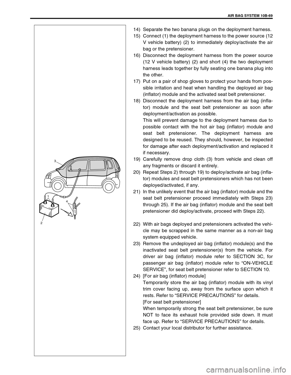
15) Connect (1) the deployment harness to the power source (12
V vehicle battery) (2) to immediately deploy/activate the air
bag or the pretensioner.
16) Disconnect the deployment harness from the power source
(12 V vehicle battery) (2) and short (4) the two deployment
harness leads together by fully seating one banana plug into
the other.
17) Put on a pair of shop gloves to protect your hands from pos-
sible irritation and heat when handling the deployed air bag
(inflator) module and the activated seat belt pretensioner.
18) Disconnect the deployment harness from the air bag (infla-
tor) module and the seat belt pretensioner as soon after
deployment/activation as possible.
This will prevent damage to the deployment harness due to
possible contact with the hot air bag (inflator) module and
seat belt pretensioner. The deployment harness are
designed to be reused. They should, however, be inspected
for damage after each deployment/activation and replaced it
if necessary.
19) Carefully remove drop cloth (3) from vehicle and clean off
any fragments or discard it entirely.
20) Repeat Steps 2) through 19) to deploy/activate air bag (infla-
tor) modules and seat belt pretensioners which has not been
deployed/activated, if any.
21) In the unlikely event that the air bag (inflator) module and the
seat belt pretensioner proceed immediately with Steps 23)
through 25). If the air bag (inflator) module and the seat belt
pretensioner did deploy/activate, proceed with Steps 22).
22) With air bags deployed and pretensioners activated the vehi-
cle may be scrapped in the same manner as a non-air bag
system equipped vehicle.
23) Remove the undeployed air bag (inflator) module(s) and the
inactivated seat belt pretensioner(s) from the vehicle. For
driver air bag (inflator) module refer to SECTION 3C, for
passenger air bag (inflator) module refer to “ON-VEHICLE
SERVICE”, for seat belt pretensioner refer to SECTION 10.
24) [For air bag (inflator) module]
Temporarily store the air bag (inflator) module with its vinyl
trim cover facing up, away from the surface upon which it
rests. Refer to “SERVICE PRECAUTIONS” for details.
[For seat belt pretensioner]
When temporarily strong the seat belt pretensioner, be sure
NOT to face its exhaust hole provided side down. It must
face up. Refer to “SERVICE PRECAUTIONS” for details.
25) Contact your local distributor for further assistance.
3
1
24