check engine SUZUKI SWIFT 2000 1.G Transmission Service User Guide
[x] Cancel search | Manufacturer: SUZUKI, Model Year: 2000, Model line: SWIFT, Model: SUZUKI SWIFT 2000 1.GPages: 447, PDF Size: 10.54 MB
Page 66 of 447
7B-24 AUTOMATIC TRANSMISSION (4 A/T)
ELECTRONIC CONTROL SYSTEM DIAGNO-
SIS
TCM has on-board diagnostic system (a system self-diagnosis
function). Investigate where the trouble is by referring to “DIAG-
NOSTIC FLOW TABLE” and “DTC TABLE” in this section.
PRECAUTIONS IN DIAGNOSING TROUBLES
[PRECAUTIONS IN IDENTIFYING DTC]
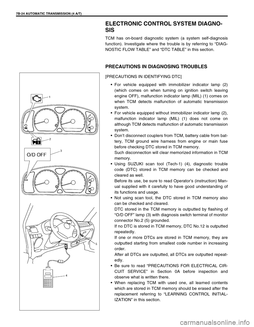
For vehicle equipped with immobilizer indicator lamp (2)
(which comes on when turning on ignition switch leaving
engine OFF), malfunction indicator lamp (MIL) (1) comes on
when TCM detects malfunction of automatic transmission
system.
For vehicle equipped without immobilizer indicator lamp (2),
malfunction indicator lamp (MIL) (1) does not come on
although TCM detects malfunction of automatic transmission
system.
Don’t disconnect couplers from TCM, battery cable from bat-
tery, TCM ground wire harness from engine or main fuse
before checking DTC stored in TCM memory.
Such disconnection will clear memorized information in TCM
memory.
Using SUZUKI scan tool (Tech-1) (4), diagnostic trouble
code (DTC) stored in TCM memory can be checked and
cleared as well.
Before its use, be sure to read Operator’s (instruction) Man-
ual supplied with it carefully to have good understanding of
its functions and usage.
Not using scan tool, the DTC stored in TCM memory also
can be checked and cleared.
DTC stored in the TCM memory is outputted by flashing of
“O/D OFF” lamp (3) with diagnosis switch terminal of monitor
connector No.2 (5) grounded.
If no DTC is stored in TCM memory, DTC No.12 is outputted
repeatedly.
If one or more DTCs are stored in TCM memory, they are
outputted starting from smallest code number in increasing
order.
After all DTCs are outputted, all DTCs are outputted repeat-
edly.
Be sure to read “PRECAUTIONS FOR ELECTRICAL CIR-
CUIT SERVICE” in Section 0A before inspection and
observe what is written there.
When replacing TCM with used one, all learned contents
which are stored in TCM memory should be erased after the
replacement referring to “LEARNING CONTROL INITIAL-
IZATION” in this section.
Page 79 of 447
AUTOMATIC TRANSMISSION (4 A/T) 7B-37
DTC P0741 (DTC NO.29) TCC (LOCK-UP) SOLENOID PERFORMANCE OR STUCK OFF
Step Action Yes No
1Was “AUTOMATIC TRANSMISSION DIAG-
NOSTIC FLOW TABLE” performed?Go to Step 2. Go to “AUTOMATIC
TRANSMISSION DIAG-
NOSTIC FLOW TABLE”.
2 Check TCC (lock-up) solenoid referring to
“SHIFT SOLENOID VALVES” in this section.
Is it in good condition?Go to Step 3. Replace TCC (lock-up)
solenoid.
3 Check valve body for fluid passage clog, or
lock-up control valve, secondary regulator valve
or signal valve stuck, referring to “TRANSMIS-
SION UNIT REPAIR OVERHAUL” in this sec-
tion.
Are they in good condition?Go to Step 4. Faulty valve body.
4 Substitute a known-good torque converter and
recheck.
Is it OK?Torque converter mal-
function.Overhaul and repair auto-
matic transmission.
DTC DETECTING CONDITION
Difference between turbine rev. and engine rev. too close even though TCM ordered to turn OFF lock-up.
Difference between turbine rev. and engine rev. too wide even though TCM ordered to turn ON lock-up.
Page 83 of 447
AUTOMATIC TRANSMISSION (4 A/T) 7B-41
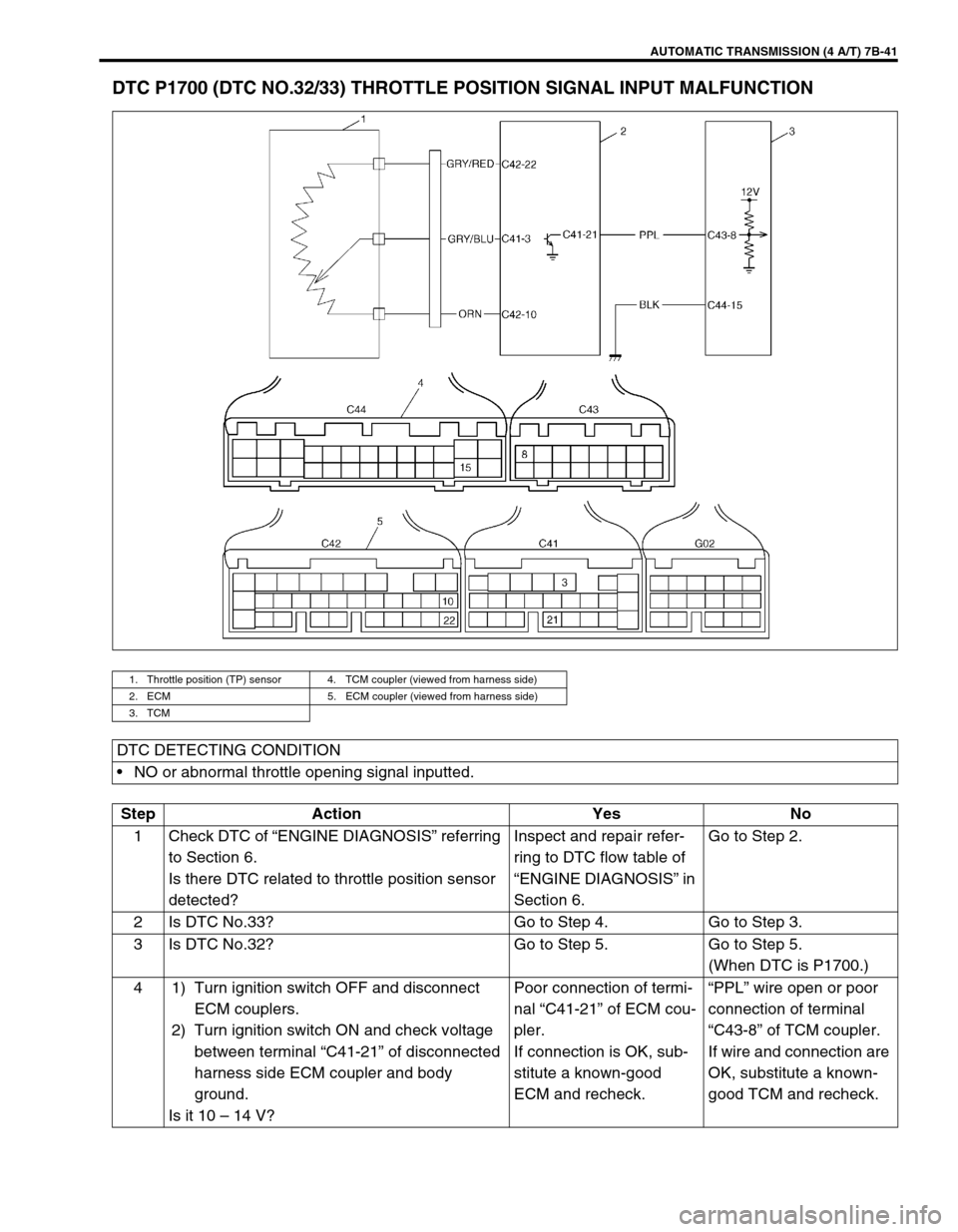
DTC P1700 (DTC NO.32/33) THROTTLE POSITION SIGNAL INPUT MALFUNCTION
1. Throttle position (TP) sensor 4. TCM coupler (viewed from harness side)
2. ECM 5. ECM coupler (viewed from harness side)
3. TCM
DTC DETECTING CONDITION
NO or abnormal throttle opening signal inputted.
Step Action Yes No
1 Check DTC of “ENGINE DIAGNOSIS” referring
to Section 6.
Is there DTC related to throttle position sensor
detected?Inspect and repair refer-
ring to DTC flow table of
“ENGINE DIAGNOSIS” in
Section 6.Go to Step 2.
2 Is DTC No.33? Go to Step 4. Go to Step 3.
3 Is DTC No.32? Go to Step 5. Go to Step 5.
(When DTC is P1700.)
4 1) Turn ignition switch OFF and disconnect
ECM couplers.
2) Turn ignition switch ON and check voltage
between terminal “C41-21” of disconnected
harness side ECM coupler and body
ground.
Is it 10 – 14 V?Poor connection of termi-
nal “C41-21” of ECM cou-
pler.
If connection is OK, sub-
stitute a known-good
ECM and recheck.“PPL” wire open or poor
connection of terminal
“C43-8” of TCM coupler.
If wire and connection are
OK, substitute a known-
good TCM and recheck.
Page 87 of 447
AUTOMATIC TRANSMISSION (4 A/T) 7B-45
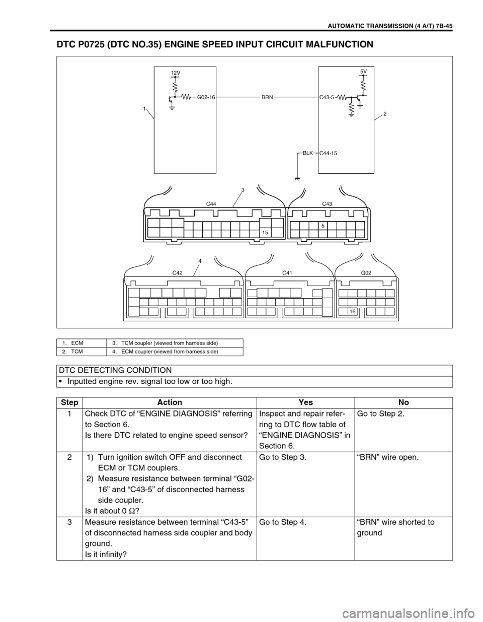
DTC P0725 (DTC NO.35) ENGINE SPEED INPUT CIRCUIT MALFUNCTION
1. ECM 3. TCM coupler (viewed from harness side)
2. TCM 4. ECM coupler (viewed from harness side)
DTC DETECTING CONDITION
Inputted engine rev. signal too low or too high.
Step Action Yes No
1 Check DTC of “ENGINE DIAGNOSIS” referring
to Section 6.
Is there DTC related to engine speed sensor?Inspect and repair refer-
ring to DTC flow table of
“ENGINE DIAGNOSIS” in
Section 6.Go to Step 2.
2 1) Turn ignition switch OFF and disconnect
ECM or TCM couplers.
2) Measure resistance between terminal “G02-
16” and “C43-5” of disconnected harness
side coupler.
Is it about 0 Ω
?Go to Step 3.“BRN” wire open.
3 Measure resistance between terminal “C43-5”
of disconnected harness side coupler and body
ground.
Is it infinity?Go to Step 4.“BRN” wire shorted to
ground
Page 89 of 447
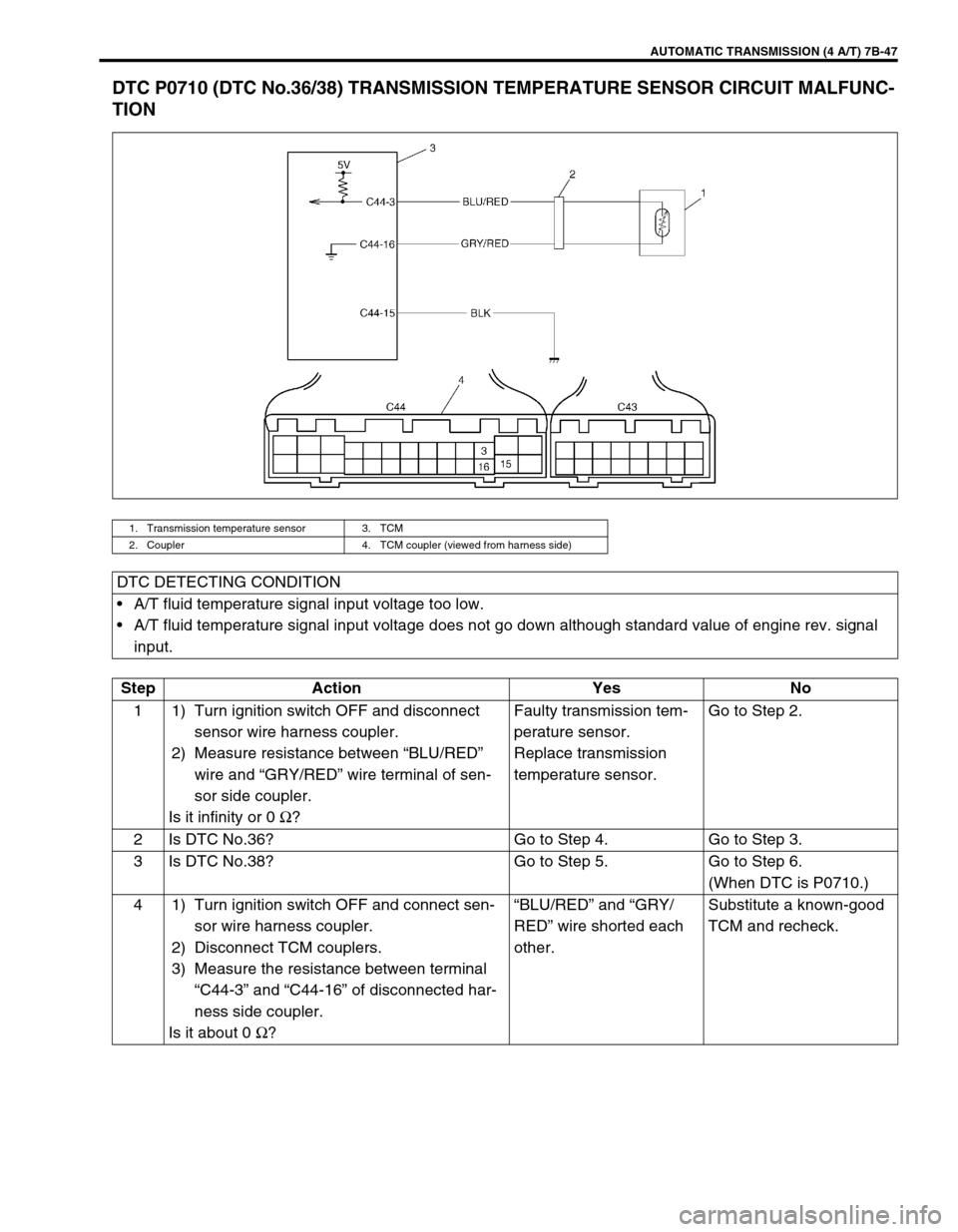
AUTOMATIC TRANSMISSION (4 A/T) 7B-47
DTC P0710 (DTC No.36/38) TRANSMISSION TEMPERATURE SENSOR CIRCUIT MALFUNC-
TION
1. Transmission temperature sensor 3. TCM
2. Coupler 4. TCM coupler (viewed from harness side)
DTC DETECTING CONDITION
A/T fluid temperature signal input voltage too low.
A/T fluid temperature signal input voltage does not go down although standard value of engine rev. signal
input.
Step Action Yes No
1 1) Turn ignition switch OFF and disconnect
sensor wire harness coupler.
2) Measure resistance between “BLU/RED”
wire and “GRY/RED” wire terminal of sen-
sor side coupler.
Is it infinity or 0 Ω
?Faulty transmission tem-
perature sensor.
Replace transmission
temperature sensor.Go to Step 2.
2 Is DTC No.36? Go to Step 4. Go to Step 3.
3 Is DTC No.38? Go to Step 5. Go to Step 6.
(When DTC is P0710.)
4 1) Turn ignition switch OFF and connect sen-
sor wire harness coupler.
2) Disconnect TCM couplers.
3) Measure the resistance between terminal
“C44-3” and “C44-16” of disconnected har-
ness side coupler.
Is it about 0 Ω
?“BLU/RED” and “GRY/
RED” wire shorted each
other.Substitute a known-good
TCM and recheck.
Page 90 of 447
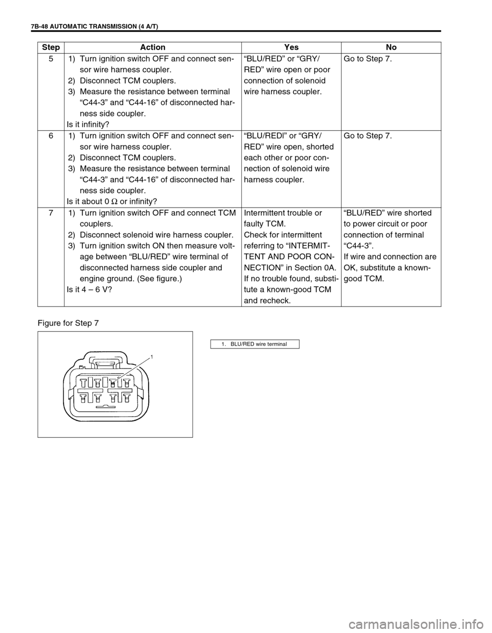
7B-48 AUTOMATIC TRANSMISSION (4 A/T)
Figure for Step 75 1) Turn ignition switch OFF and connect sen-
sor wire harness coupler.
2) Disconnect TCM couplers.
3) Measure the resistance between terminal
“C44-3” and “C44-16” of disconnected har-
ness side coupler.
Is it infinity?“BLU/RED” or “GRY/
RED” wire open or poor
connection of solenoid
wire harness coupler.Go to Step 7.
6 1) Turn ignition switch OFF and connect sen-
sor wire harness coupler.
2) Disconnect TCM couplers.
3) Measure the resistance between terminal
“C44-3” and “C44-16” of disconnected har-
ness side coupler.
Is it about 0 Ω
or infinity?“BLU/REDl” or “GRY/
RED” wire open, shorted
each other or poor con-
nection of solenoid wire
harness coupler.Go to Step 7.
7 1) Turn ignition switch OFF and connect TCM
couplers.
2) Disconnect solenoid wire harness coupler.
3) Turn ignition switch ON then measure volt-
age between “BLU/RED” wire terminal of
disconnected harness side coupler and
engine ground. (See figure.)
Is it 4 – 6 V?Intermittent trouble or
faulty TCM.
Check for intermittent
referring to “INTERMIT-
TENT AND POOR CON-
NECTION” in Section 0A.
If no trouble found, substi-
tute a known-good TCM
and recheck.“BLU/RED” wire shorted
to power circuit or poor
connection of terminal
“C44-3”.
If wire and connection are
OK, substitute a known-
good TCM. Step Action Yes No
1. BLU/RED wire terminal
Page 93 of 447
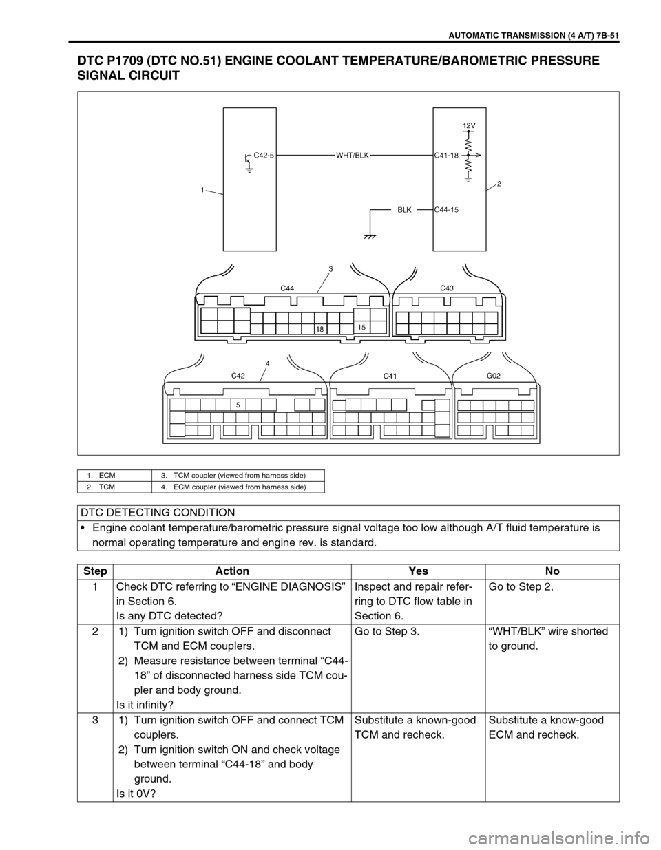
AUTOMATIC TRANSMISSION (4 A/T) 7B-51
DTC P1709 (DTC NO.51) ENGINE COOLANT TEMPERATURE/BAROMETRIC PRESSURE
SIGNAL CIRCUIT
1. ECM 3. TCM coupler (viewed from harness side)
2. TCM 4. ECM coupler (viewed from harness side)
DTC DETECTING CONDITION
Engine coolant temperature/barometric pressure signal voltage too low although A/T fluid temperature is
normal operating temperature and engine rev. is standard.
Step Action Yes No
1 Check DTC referring to “ENGINE DIAGNOSIS”
in Section 6.
Is any DTC detected?Inspect and repair refer-
ring to DTC flow table in
Section 6.Go to Step 2.
2 1) Turn ignition switch OFF and disconnect
TCM and ECM couplers.
2) Measure resistance between terminal “C44-
18” of disconnected harness side TCM cou-
pler and body ground.
Is it infinity?Go to Step 3.“WHT/BLK” wire shorted
to ground.
3 1) Turn ignition switch OFF and connect TCM
couplers.
2) Turn ignition switch ON and check voltage
between terminal “C44-18” and body
ground.
Is it 0V?Substitute a known-good
TCM and recheck.Substitute a know-good
ECM and recheck.
Page 95 of 447
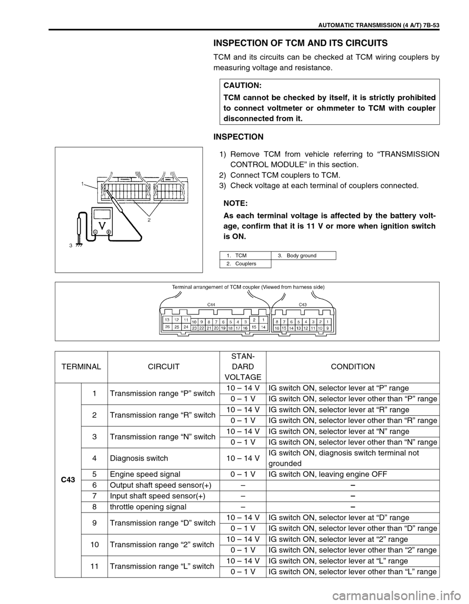
AUTOMATIC TRANSMISSION (4 A/T) 7B-53
INSPECTION OF TCM AND ITS CIRCUITS
TCM and its circuits can be checked at TCM wiring couplers by
measuring voltage and resistance.
INSPECTION
1) Remove TCM from vehicle referring to “TRANSMISSION
CONTROL MODULE” in this section.
2) Connect TCM couplers to TCM.
3) Check voltage at each terminal of couplers connected.CAUTION:
TCM cannot be checked by itself, it is strictly prohibited
to connect voltmeter or ohmmeter to TCM with coupler
disconnected from it.
NOTE:
As each terminal voltage is affected by the battery volt-
age, confirm that it is 11 V or more when ignition switch
is ON.
1. TCM 3. Body ground
2. Couplers
TERMINAL CIRCUITSTAN-
DARD
VOLTAGECONDITION
C431 Transmission range “P” switch10 – 14 V IG switch ON, selector lever at “P” range
0 – 1 V IG switch ON, selector lever other than “P” range
2 Transmission range “R” switch10 – 14 V IG switch ON, selector lever at “R” range
0 – 1 V IG switch ON, selector lever other than “R” range
3 Transmission range “N” switch10 – 14 V IG switch ON, selector lever at “N” range
0 – 1 V IG switch ON, selector lever other than “N” range
4 Diagnosis switch 10 – 14 VIG switch ON, diagnosis switch terminal not
grounded
5 Engine speed signal 0 – 1 V IG switch ON, leaving engine OFF
6 Output shaft speed sensor(+)––
7 Input shaft speed sensor(+)––
8 throttle opening signal––
9 Transmission range “D” switch10 – 14 V IG switch ON, selector lever at “D” range
0 – 1 V IG switch ON, selector lever other than “D” range
10 Transmission range “2” switch10 – 14 V IG switch ON, selector lever at “2” range
0 – 1 V IG switch ON, selector lever other than “2” range
11 Transmission range “L” switch10 – 14 V IG switch ON, selector lever at “L” range
0 – 1 V IG switch ON, selector lever other than “L” range
Page 97 of 447
AUTOMATIC TRANSMISSION (4 A/T) 7B-55
ON-VEHICLE SERVICE
MAINTENANCE SERVICE
FLUID LEVEL AT NORMAL OPERATING TEMPERA-
TURE
INSPECTION
1) Stop vehicle and place it level.
2) Apply parking brake and place chocks against wheels.
3) With selector at P position, start engine.
4) Warm up engine till fluid temperature reaches normal oper-
ating temperature (70 – 80°C/158 – 176°F). As a guide to
check fluid temperature, warm up engine to normal operat-
ing temperature.
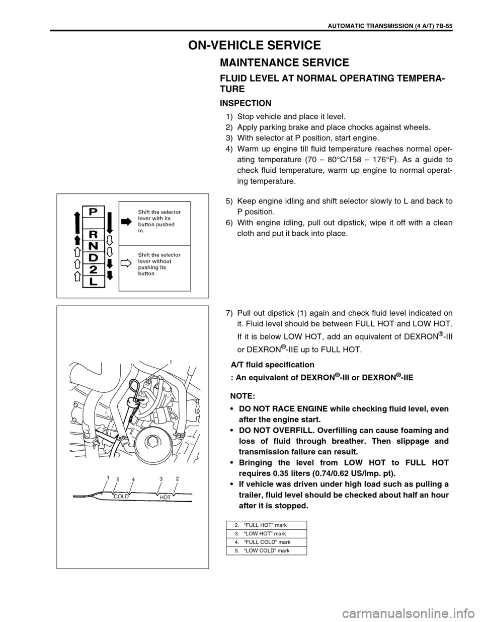
5) Keep engine idling and shift selector slowly to L and back to
P position.
6) With engine idling, pull out dipstick, wipe it off with a clean
cloth and put it back into place.
7) Pull out dipstick (1) again and check fluid level indicated on
it. Fluid level should be between FULL HOT and LOW HOT.
If it is below LOW HOT, add an equivalent of DEXRON
®-III
or DEXRON
®-IIE up to FULL HOT.
A/T fluid specification
: An equivalent of DEXRON
®-III or DEXRON®-IIE
NOTE:
DO NOT RACE ENGINE while checking fluid level, even
after the engine start.
DO NOT OVERFILL. Overfilling can cause foaming and
loss of fluid through breather. Then slippage and
transmission failure can result.
Bringing the level from LOW HOT to FULL HOT
requires 0.35 liters (0.74/0.62 US/Imp. pt).
If vehicle was driven under high load such as pulling a
trailer, fluid level should be checked about half an hour
after it is stopped.
2.“FULL HOT” mark
3.“LOW HOT” mark
4.“FULL COLD” mark
5.“LOW COLD” mark
1
Page 98 of 447
7B-56 AUTOMATIC TRANSMISSION (4 A/T)
FLUID LEVEL AT ROOM TEMPERATURE
INSPECTION
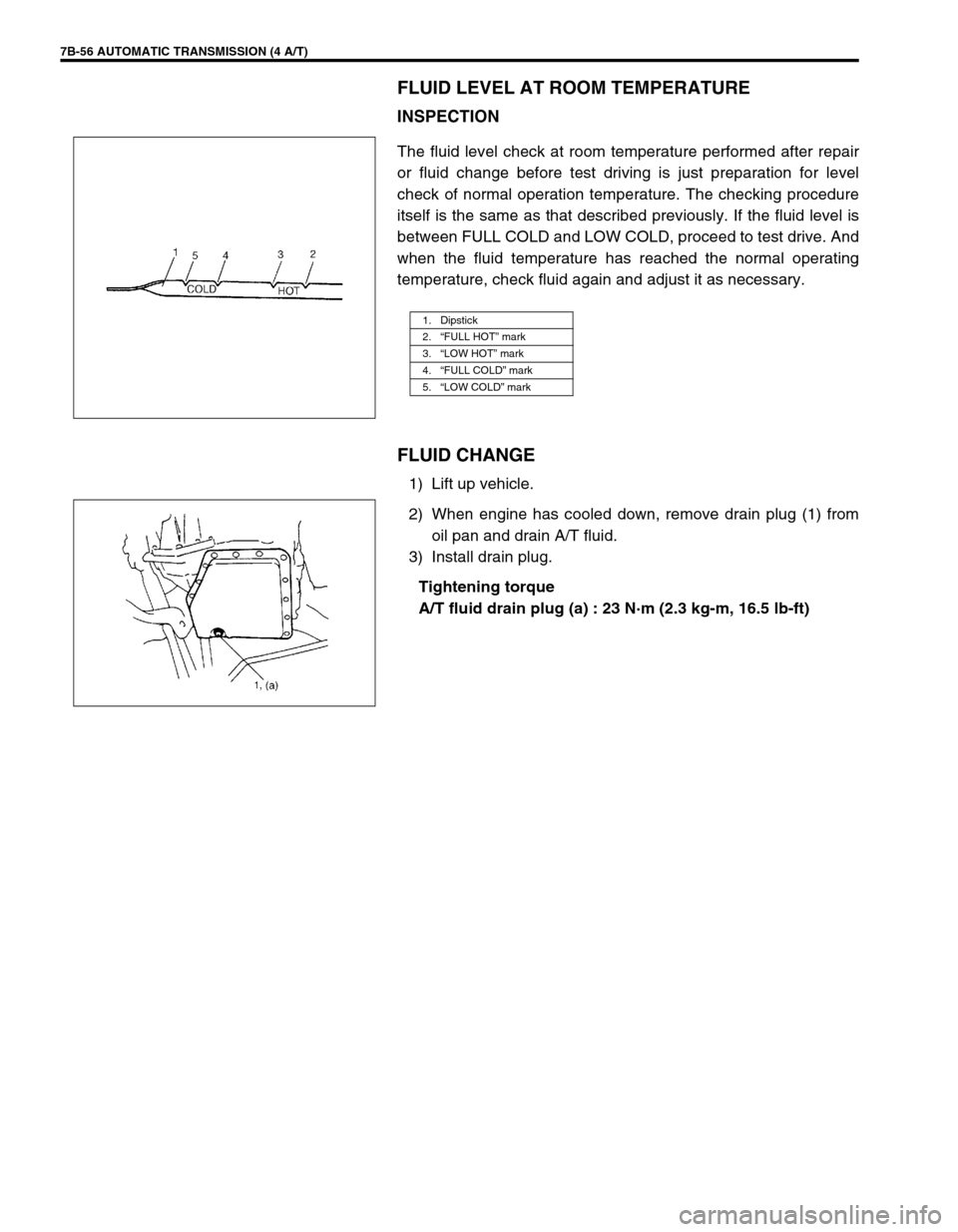
The fluid level check at room temperature performed after repair
or fluid change before test driving is just preparation for level
check of normal operation temperature. The checking procedure
itself is the same as that described previously. If the fluid level is
between FULL COLD and LOW COLD, proceed to test drive. And
when the fluid temperature has reached the normal operating
temperature, check fluid again and adjust it as necessary.
FLUID CHANGE
1) Lift up vehicle.
2) When engine has cooled down, remove drain plug (1) from
oil pan and drain A/T fluid.
3) Install drain plug.
Tightening torque
A/T fluid drain plug (a) : 23 N·m (2.3 kg-m, 16.5 lb-ft)
1. Dipstick
2.“FULL HOT” mark
3.“LOW HOT” mark
4.“FULL COLD” mark
5.“LOW COLD” mark