dimensions SUZUKI SWIFT 2000 1.G Transmission Service Workshop Manual
[x] Cancel search | Manufacturer: SUZUKI, Model Year: 2000, Model line: SWIFT, Model: SUZUKI SWIFT 2000 1.GPages: 447, PDF Size: 10.54 MB
Page 150 of 447

7B-108 AUTOMATIC TRANSMISSION (4 A/T)
Valve spring dimensions (Reference)
Lower Valve Body
1) Remove oil strainers (1).
2) Remove solenoid valves, if still attached.
3) Remove keys (2) and pull out all sleeve, plug, spring and
valves.
Valve spring dimensions (Reference)Spring Free length
“a” (mm)Outside diameter
“b” (mm)
Primary regula-
tor valve spring79.2 18.0
Lock-up control
valve spring31.1 8.5
Lock-up signal
valve spring36.1 8.5
3. Fail valve No.1 sleeve
4. Fail valve No.1
5. Cooler by-pass valve
6. Cooler by-pass valve spring
7. Manual valve
8. Secondary regulator valve
9. Secondary regulator valve spring
10. Secondary regulator valve plug
Spring Free length
“a” (mm)Outside diame-
ter “b” (mm)
Secondary regula-
tor valve spring38.7 8.8
Cooler by-pass
valve spring22.8 8.0
Page 305 of 447

BODY SERVICE 9-1
6F1
6F2
6G
6H
6K
7A
7A1
7B1
7C1
7D
7E
7F
8A
8B
8C
8D
8E
9
10
10A
10B
SECTION 9
BODY SERVICE
CONTENTS
GLASS, WINDOWS AND MIRRORS ................. 9-2
FRONT DOOR GLASS ................................... 9-2
FRONT DOOR WINDOW REGULATOR ........ 9-6
DOOR MIRROR .......................................... 9-7
REAR DOOR GLASS (IF EQUIPPED) ....... 9-8
REAR DOOR WINDOW REGULATOR ........ 9-11
WINDOW SHIELD ........................................ 9-12
QUARTER WINDOW .................................... 9-17
BACK DOOR GLASS .................................... 9-18
BODY STRUCTURE......................................... 9-19
FRONT DOOR ASSEMBLY .......................... 9-19
REAR DOOR ASSEMBLY ............................ 9-22
BACK DOOR ASSEMBLY ............................ 9-23
HOOD ........................................................... 9-25
FRONT FENDER .......................................... 9-26
FRONT BUMPER AND REAR BUMPER...... 9-27
ROOF RAIL (IF EQUIPPED) ......................... 9-28
BODY DIMENSIONS .................................... 9-29
ENGINE ROOM ........................................ 9-29
BACK DOOR ............................................. 9-30
SIDE BODY ............................................... 9-31UNDER BODY .......................................... 9-34
PANEL CLEARANCE ................................... 9-36
INSTRUMENTATION AND DRIVER
INFORMATION................................................. 9-38
INSTRUMENT PANEL .................................. 9-38
SEATS .............................................................. 9-40
FRONT SEAT ............................................... 9-40
REAR SEAT.................................................. 9-41
SECURITY AND LOCKS ................................. 9-42
FRONT DOOR LOCK ASSEMBLY............... 9-42
REAR DOOR LOCK ASSEMBLY (IF
EQUIPPED) .................................................. 9-44
BACK DOOR LOCK ASSEMBLY ................. 9-45
KEY CODING ............................................... 9-46
KEY USAGE AND IDENTIFICATION ....... 9-46
IGNITION SWITCH LOCK CYLINDER ..... 9-47
EXTERIOR AND INTERIOR TRIM ................... 9-47
FLOOR CARPET .......................................... 9-47
HEAD LINING ............................................... 9-48
PAINT AND COATINGS .................................. 9-50 WARNING:
For vehicles equipped with Supplemental Restraint (Air Bag) System:
Service on and around the air bag system components or wiring must be performed only by an
authorized SUZUKI dealer. Refer to “Air Bag System Components and Wiring Location View” under
“General Description” in air bag system section in order to confirm whether you are performing ser-
vice on or near the air bag system components or wiring. Please observe all WARNINGS and “Ser-
vice Precautions” under “On-Vehicle Service” in air bag system section before performing service
on or around the air bag system components or wiring. Failure to follow WARNINGS could result in
unintentional activation of the system or could render the system inoperative. Either of these two
conditions may result in severe injury.
Technical service work must be started at least 90 seconds after the ignition switch is turned to the
“LOCK” position and the negative cable is disconnected from the battery. Otherwise, the system
may be activated by reserve energy in the Sensing and Diagnostic Module (SDM).
When body servicing, if shock may be applied to air bag system component parts, remove those
parts beforehand. (Refer to Section 10B.)
NOTE:
Fasteners are important attaching parts in that they could affect the performance of vital components
and systems, and / or could result in major repair expense. They must be replaced with one of the
same part number of with an equivalent part if replacement becomes necessary.
Do not use a replacement part of lesser quality or substitute a design. Torque values must be used as
specified during reassembly to assure proper retention of these parts.
Page 333 of 447

BODY SERVICE 9-29
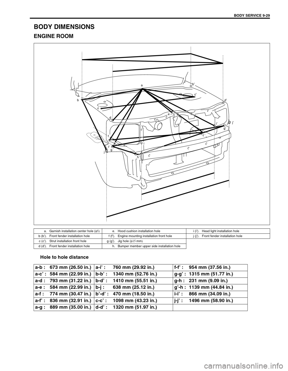
BODY DIMENSIONS
ENGINE ROOM
Hole to hole distance
a. Garnish installation center hole (φ5)
e. Hood cushion installation hole i (i’). Head light installation hole
b (b’). Front fender installation hole f (f’). Engine mounting installation front hole j (j’). Front fender installation hole
c (c’). Strut installation front hole g (g’). Jig hole (φ15
mm)
d (d’). Front fender installation hole h. Bumper member upper side installation hole
a-b : 673 mm (26.50 in.) a-i’ : 760 mm (29.92 in.) f-f’ : 954 mm (37.56 in.)
a-c’ : 584 mm (22.99 in.) b-b’ : 1340 mm (52.76 in.) g-g’ : 1315 mm (51.77 in.)
a-d : 793 mm (31.22 in.) b-d’ : 1410 mm (55.51 in.) g-h : 231 mm (9.09 in.)
a-e : 584 mm (22.99 in.) b-j : 638 mm (25.12 in.) g’-h : 1139 mm (44.84 in.)
a-f : 774 mm (30.47 in.) b’-d’ : 470 mm (18.50 in.) i-i’ : 866 mm (34.09 in.)
a-f’ : 836 mm (32.91 in.) c-c’ : 1098 mm (43.23 in.) j-j’ : 1496 mm (58.90 in.)
a-g : 889 mm (35.00 in.) d-d’ : 1320 mm (51.97 in.)
ba
b’
e
f
h
gj
i
d
c
i’
f’ c’
d’
j’
g’