check oil SUZUKI SWIFT 2000 1.G Transmission Service User Guide
[x] Cancel search | Manufacturer: SUZUKI, Model Year: 2000, Model line: SWIFT, Model: SUZUKI SWIFT 2000 1.GPages: 447, PDF Size: 10.54 MB
Page 52 of 447
7B-10 AUTOMATIC TRANSMISSION (4 A/T)
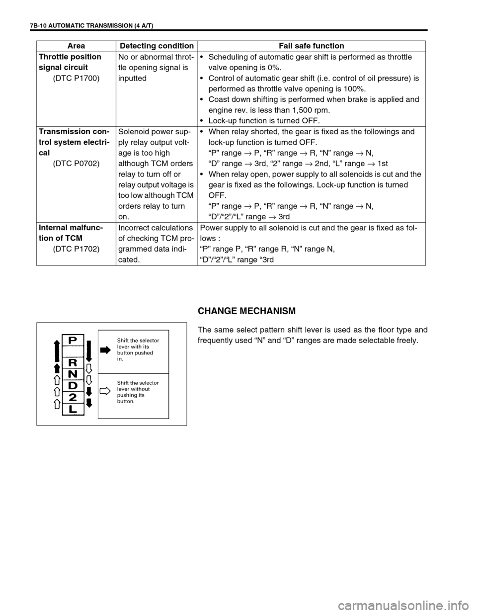
CHANGE MECHANISM
The same select pattern shift lever is used as the floor type and
frequently used “N” and “D” ranges are made selectable freely. Throttle position
signal circuit
(DTC P1700)No or abnormal throt-
tle opening signal is
inputtedScheduling of automatic gear shift is performed as throttle
valve opening is 0%.
Control of automatic gear shift (i.e. control of oil pressure) is
performed as throttle valve opening is 100%.
Coast down shifting is performed when brake is applied and
engine rev. is less than 1,500 rpm.
Lock-up function is turned OFF.
Transmission con-
trol system electri-
cal
(DTC P0702)Solenoid power sup-
ply relay output volt-
age is too high
although TCM orders
relay to turn off or
relay output voltage is
too low although TCM
orders relay to turn
on.When relay shorted, the gear is fixed as the followings and
lock-up function is turned OFF.
“P” range →
P, “R” range →
R, “N” range →
N,
“D” range →
3rd, “2” range →
2nd, “L” range →
1st
When relay open, power supply to all solenoids is cut and the
gear is fixed as the followings. Lock-up function is turned
OFF.
“P” range →
P, “R” range →
R, “N” range →
N,
“D”/“2”/“L” range →
3rd
Internal malfunc-
tion of TCM
(DTC P1702)Incorrect calculations
of checking TCM pro-
grammed data indi-
cated.Power supply to all solenoid is cut and the gear is fixed as fol-
lows :
“P” range P, “R” range R, “N” range N,
“D”/“2”/“L” range “3rd Area Detecting condition Fail safe function
Page 58 of 447
7B-16 AUTOMATIC TRANSMISSION (4 A/T)
2. DIAGNOSTIC TROUBLE CODE (DTC) CHECK, RECORD AND CLEARANCE
To check DTC, refer to “DTC CHECK” in this section. When a DTC exists, it means existence of a malfunction in
the system represented by that code but whether it still exists (current) or it occurred in the past and has gone
(history) is unknown. To know it, clear this DTC once (Refer to “DTC CLEARANCE” in this section.), perform
test drive and/or “TROUBLE SYMPTOM CONFIRMATION” in this section and then check DTC again as
described in “DTC CHECK”. Attempt to diagnose the trouble based on the DTC recorded in this step only or fail-
ure to clear the DTC in this step may mislead the diagnosis or make diagnosing difficult. Even after checking the
DTC with the SUZUKI scan tool, diagnosis should be performed according to this flow chart to check TCM for
proper self-diagnosis function.
3 and 4. VISUAL INSPECTION
As a preliminary step, perform visual check of the following items that support proper function of the automatic
transmission.
5.TROUBLE SYMPTOM CONFIRMATION
Check if what the customer claimed in “CUSTOMER COMPLAINT ANALYSIS” is actually found in the vehicle
and if that symptom is found, whether it is identified as a failure. (This step should be shared with the customer
if possible.)
When the symptom is not actually found, possibility is :
The symptom occurs under certain conditions.
----- Retry with the vehicle under different conditions.
The trouble occurred only temporarily and normal operation has been restored.
----- Perform “DTC CHECK” and if the diagnostic trouble code is indicated, inspect according to the flow
table for that DTC.
6 and 7. RECHECKING AND RECORD OF DTC
Refer to “DTC CHECK” in this section.INSPECTION ITEM REFERRING SECTION
Engine oil ----- level, leakage Section 0B
Engine coolant ----- level, leakage Section 0B
A/T fluid ----- level, leakage, color Section 0B
Battery ----- fluid level, corrosion of terminal
A/T fluid hoses ----- disconnection, looseness, deterioration
Connectors of electric wire harness ----- disconnection, friction Section 8
Fuses ----- burning Section 8
Parts ----- installation, bolt ----- looseness
Parts ----- deformation
Other parts that can be checked visually
Also add following items at engine start.
Indicator, warning lights in combination meter ----- ON
(indicating abnormality in system) or OFFSection 8C
Other parts that can be checked visually
Page 64 of 447
7B-22 AUTOMATIC TRANSMISSION (4 A/T)
LINE PRESSURE TEST
Purpose of this test is to check operating conditions of each part
by measuring fluid pressure in fluid pressure line.
Line pressure test requires following conditions.
Automatic fluid is at normal operating temperature (70 –
80°C /158 – 176°F).
Fluid is filled to proper level (between FULL and LOW on
dipstick).
1) Apply parking brake securely and place chocks against
wheels.
2) Remove fluid pressure check hole plug bolt.
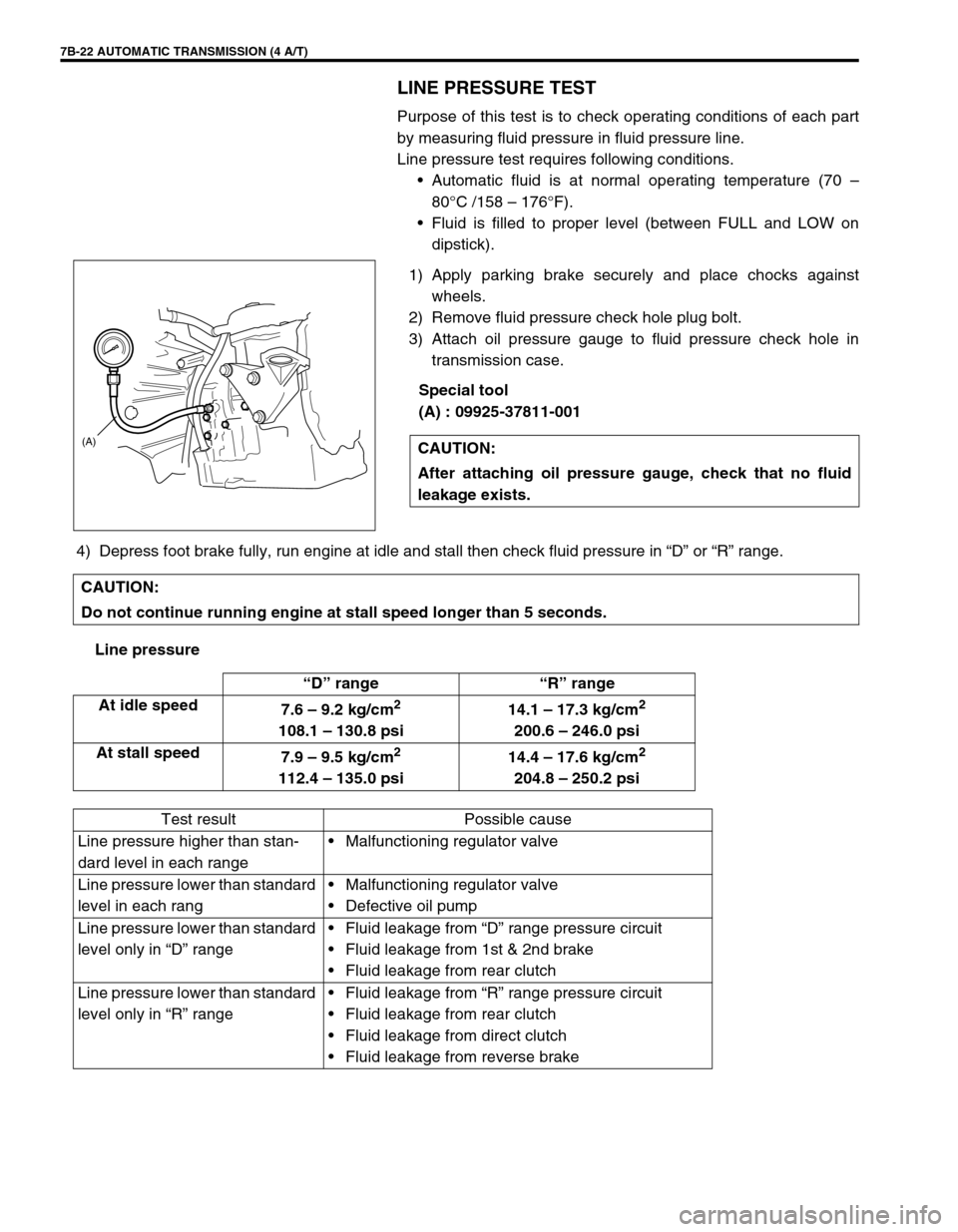
3) Attach oil pressure gauge to fluid pressure check hole in
transmission case.
Special tool
(A) : 09925-37811-001
4) Depress foot brake fully, run engine at idle and stall then check fluid pressure in “D” or “R” range.
Line pressureCAUTION:
After attaching oil pressure gauge, check that no fluid
leakage exists.
(A)
CAUTION:
Do not continue running engine at stall speed longer than 5 seconds.
“D” range “R” range
At idle speed
7.6 – 9.2 kg/cm
2
108.1 – 130.8 psi14.1 – 17.3 kg/cm
2
200.6 – 246.0 psi
At stall speed
7.9 – 9.5 kg/cm
2
112.4 – 135.0 psi14.4 – 17.6 kg/cm
2
204.8 – 250.2 psi
Test result Possible cause
Line pressure higher than stan-
dard level in each rangeMalfunctioning regulator valve
Line pressure lower than standard
level in each rangMalfunctioning regulator valve
Defective oil pump
Line pressure lower than standard
level only in “D” rangeFluid leakage from “D” range pressure circuit
Fluid leakage from 1st & 2nd brake
Fluid leakage from rear clutch
Line pressure lower than standard
level only in “R” rangeFluid leakage from “R” range pressure circuit
Fluid leakage from rear clutch
Fluid leakage from direct clutch
Fluid leakage from reverse brake
Page 98 of 447
7B-56 AUTOMATIC TRANSMISSION (4 A/T)
FLUID LEVEL AT ROOM TEMPERATURE
INSPECTION
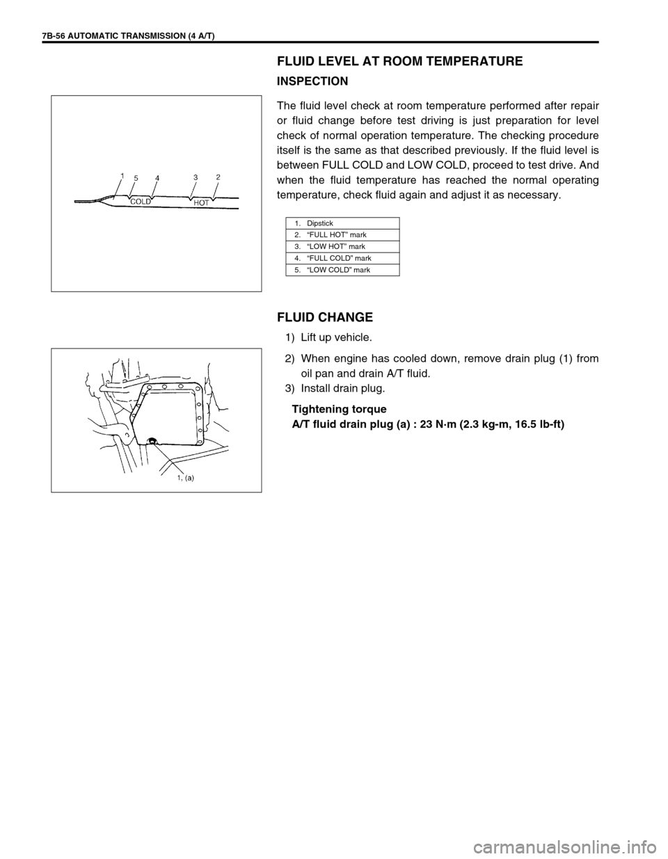
The fluid level check at room temperature performed after repair
or fluid change before test driving is just preparation for level
check of normal operation temperature. The checking procedure
itself is the same as that described previously. If the fluid level is
between FULL COLD and LOW COLD, proceed to test drive. And
when the fluid temperature has reached the normal operating
temperature, check fluid again and adjust it as necessary.
FLUID CHANGE
1) Lift up vehicle.
2) When engine has cooled down, remove drain plug (1) from
oil pan and drain A/T fluid.
3) Install drain plug.
Tightening torque
A/T fluid drain plug (a) : 23 N·m (2.3 kg-m, 16.5 lb-ft)
1. Dipstick
2.“FULL HOT” mark
3.“LOW HOT” mark
4.“FULL COLD” mark
5.“LOW COLD” mark
Page 107 of 447

AUTOMATIC TRANSMISSION (4 A/T) 7B-65
O/D OFF SWITCH
INSPECTION
1) Remove console box.
2) Disconnect O/D off switch coupler (1).
3) Check continuity between O/D off switch terminals.
O/D OFF switch specification
SHIFT SOLENOID VALVES AND TRANSMIS-
SION TEMPERATURE SENSOR
REMOVAL
1) Disconnect negative cable at battery.
2) Drain A/T fluid.
3) Remove A/T oil pan (1).
4) Disconnect transmission temp. sensor coupler (3).
5) Remove A/T oil strainer (2) and transmission temp. sensor
(1). O/D off switch ON OFF
Continuity Continuity No continuity
2. O/D off switch ON
3. O/D off switch OFF
Page 130 of 447
7B-88 AUTOMATIC TRANSMISSION (4 A/T)
DISASSEMBLY/ASSEMBLY OF SUBASSEMBLY
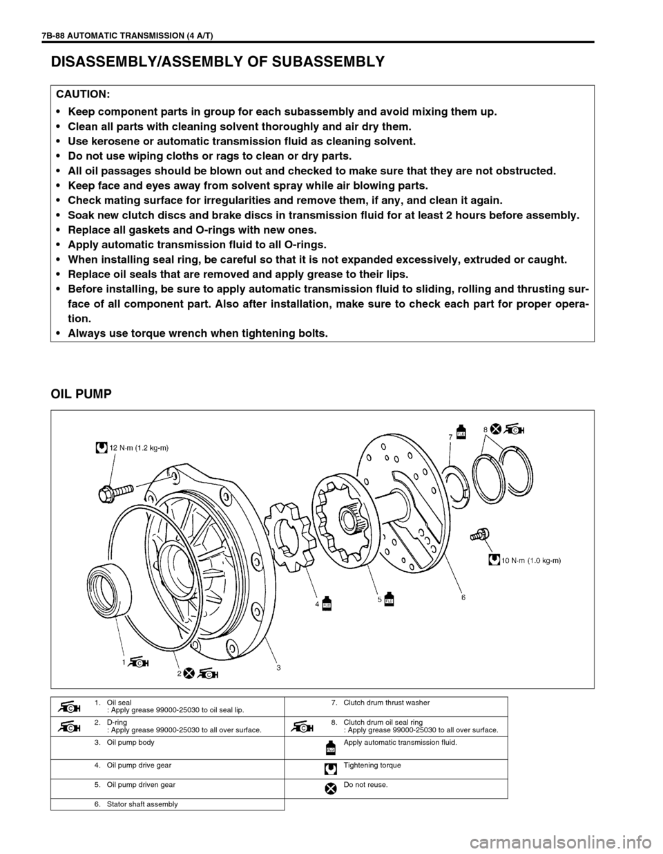
OIL PUMP
CAUTION:
Keep component parts in group for each subassembly and avoid mixing them up.
Clean all parts with cleaning solvent thoroughly and air dry them.
Use kerosene or automatic transmission fluid as cleaning solvent.
Do not use wiping cloths or rags to clean or dry parts.
All oil passages should be blown out and checked to make sure that they are not obstructed.
Keep face and eyes away from solvent spray while air blowing parts.
Check mating surface for irregularities and remove them, if any, and clean it again.
Soak new clutch discs and brake discs in transmission fluid for at least 2 hours before assembly.
Replace all gaskets and O-rings with new ones.
Apply automatic transmission fluid to all O-rings.
When installing seal ring, be careful so that it is not expanded excessively, extruded or caught.
Replace oil seals that are removed and apply grease to their lips.
Before installing, be sure to apply automatic transmission fluid to sliding, rolling and thrusting sur-
face of all component part. Also after installation, make sure to check each part for proper opera-
tion.
Always use torque wrench when tightening bolts.
1. Oil seal
: Apply grease 99000-25030 to oil seal lip.7. Clutch drum thrust washer
2. D-ring
: Apply grease 99000-25030 to all over surface. 8. Clutch drum oil seal ring
: Apply grease 99000-25030 to all over surface.
3. Oil pump body Apply automatic transmission fluid.
4. Oil pump drive gear Tightening torque
5. Oil pump driven gear Do not reuse.
6. Stator shaft assembly
Page 131 of 447
AUTOMATIC TRANSMISSION (4 A/T) 7B-89
DISASSEMBLY
1) Remove D-ring from pump body.
2) Remove 2 oil seal rings and clutch drum thrust washer.
3) Remove 11 bolts.
4) Separate pump body from stator shaft assembly.
5) Remove oil seal from pump body.
INSPECTION
1) Inspect pump body oil seal.
Check for wear, damage or cracks.
Replace oil seal if necessary and apply grease to its lip por-
tion slightly when it is installed.
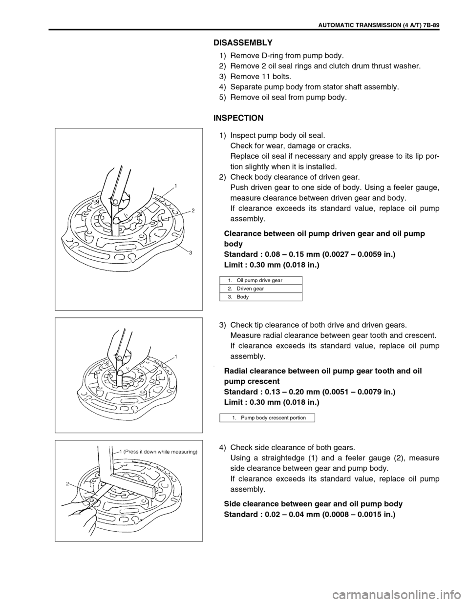
2) Check body clearance of driven gear.
Push driven gear to one side of body. Using a feeler gauge,
measure clearance between driven gear and body.
If clearance exceeds its standard value, replace oil pump
assembly.
Clearance between oil pump driven gear and oil pump
body
Standard : 0.08 – 0.15 mm (0.0027 – 0.0059 in.)
Limit : 0.30 mm (0.018 in.)
3) Check tip clearance of both drive and driven gears.
Measure radial clearance between gear tooth and crescent.
If clearance exceeds its standard value, replace oil pump
assembly.
.Radial clearance between oil pump gear tooth and oil
pump crescent
Standard : 0.13 – 0.20 mm (0.0051 – 0.0079 in.)
Limit : 0.30 mm (0.018 in.)
4) Check side clearance of both gears.
Using a straightedge (1) and a feeler gauge (2), measure
side clearance between gear and pump body.
If clearance exceeds its standard value, replace oil pump
assembly.
Side clearance between gear and oil pump body
Standard : 0.02 – 0.04 mm (0.0008 – 0.0015 in.)
1. Oil pump drive gear
2. Driven gear
3. Body
1. Pump body crescent portion
Page 132 of 447

7B-90 AUTOMATIC TRANSMISSION (4 A/T)
ASSEMBLY
1) Install pump body oil seal (1)
Use special tool and hammer to install it, and then apply
grease to its lip portion.
Special tool
(A) : 09913-85210
“A”: Grease 99000-25030
2) Install driven gear and drive gear to pump body (2) after
applying A/T fluid to gears.
3) Install stator shaft assembly to pump body and tighten 11
pump cover bolts to specification.
Tightening torque
Oil pump cover bolts (a) : 10 N·m (1.0 kg-m, 7.5 lb-ft)
4) Install 2 new oil seal rings to stator shaft.
5) Apply grease to 2 oil seal rings.
6) Install new D-ring to which grease is applied and make sure
that it is not twisted or extruded.
7) Check drive gear for smooth rotation.
Page 134 of 447

7B-92 AUTOMATIC TRANSMISSION (4 A/T)
4) Remove front clutch balancer (1) and front clutch return
spring seat (2).
5) Remove front clutch piston (3).
Blow compressed air through input shaft oil hole to remove
piston. If piston does not pop out, take it out with long nose
pliers.
6) Remove D-ring (4) from front clutch No.1 drum (5).
INSPECTION
Clutch Discs, Plates and Flange
Check that sliding surfaces of discs, plates and flanges are not
worn or burnt. If necessary, replace.
Front Clutch Return Spring Seat
Measure height of front clutch return spring.
Height of front clutch return spring
: 14.85 mm (0.585 in.)
Front Clutch Piston Lip and Front Clutch Balancer Lip
Check each lip for wear, deformation, cut, and/or hardening. If
necessary, replace.
NOTE:
If disc lining is exfoliated or discolored, replace all
discs.
Before assembling new discs, soak them in A/T fluid
for at least two hours.
NOTE:
Do not apply excessive force when measuring spring
height.
Perform measurement at several points.
Page 138 of 447
7B-96 AUTOMATIC TRANSMISSION (4 A/T)
DISASSEMBLY
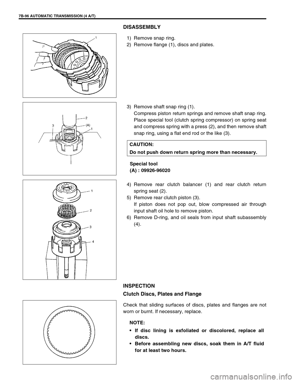
1) Remove snap ring.
2) Remove flange (1), discs and plates.
3) Remove shaft snap ring (1).
Compress piston return springs and remove shaft snap ring.
Place special tool (clutch spring compressor) on spring seat
and compress spring with a press (2), and then remove shaft
snap ring, using a flat end rod or the like (3).
Special tool
(A) : 09926-96020
4) Remove rear clutch balancer (1) and rear clutch return
spring seat (2).
5) Remove rear clutch piston (3).
If piston does not pop out, blow compressed air through
input shaft oil hole to remove piston.
6) Remove D-ring, and oil seals from input shaft subassembly
(4).
INSPECTION
Clutch Discs, Plates and Flange
Check that sliding surfaces of discs, plates and flanges are not
worn or burnt. If necessary, replace.
CAUTION:
Do not push down return spring more than necessary.
NOTE:
If disc lining is exfoliated or discolored, replace all
discs.
Before assembling new discs, soak them in A/T fluid
for at least two hours.