clutch cable SUZUKI SWIFT 2000 1.G Transmission Service User Guide
[x] Cancel search | Manufacturer: SUZUKI, Model Year: 2000, Model line: SWIFT, Model: SUZUKI SWIFT 2000 1.GPages: 447, PDF Size: 10.54 MB
Page 183 of 447

CLUTCH 7C-1
6F1
6F2
6G
6H
6K
7A1
7B1
7C1
7D
7E
7C
8A
8B
8C
8D
8E
9
10
10A
10B
SECTION 7C
CLUTCH
CONTENTS
GENERAL DESCRIPTION .............................. 7C-2
DIAGNOSIS ..................................................... 7C-3
ON-VEHICLE SERVICE .................................. 7C-4
CLUTCH CABLE .......................................... 7C-4
CLUTCH PEDAL AND CLUTCH PEDAL
BRACKET .................................................... 7C-6
CLUTCH PEDAL HEIGHT ....................... 7C-7
CLUTCH PEDAL FREE TRAVEL ............ 7C-7UNIT REPAIR OVERHAUL ............................. 7C-8
CLUTCH COVER, CLUTCH DISC AND
FLYWHEEL.................................................. 7C-8
CLUTCH RELEASE SYSTEM ................... 7C-11
TIGHTENING TORQUE SPECIFICATION.... 7C-14
REQUIRED SERVICE MATERIAL................ 7C-14
SPECIAL TOOL ............................................ 7C-14
WARNING:
For vehicles equipped with Supplemental Restraint (Air Bag) System:
Service on and around the air bag system components or wiring must be performed only by an
authorized SUZUKI dealer. Refer to “Air Bag System Components and Wiring Location View” under
“General Description” in air bag system section in order to confirm whether you are performing ser-
vice on or near the air bag system components or wiring. Please observe all WARNINGS and “Ser-
vice Precautions” under “On-Vehicle Service” in air bag system section before performing service
on or around the air bag system components or wiring. Failure to follow WARNINGS could result in
unintentional activation of the system or could render the system inoperative. Either of these two
conditions may result in severe injury.
Technical service work must be started at least 90 seconds after the ignition switch is turned to the
“LOCK” position and the negative cable is disconnected from the battery. Otherwise, the system
may be activated by reserve energy in the Sensing and Diagnostic Module (SDM).
Page 185 of 447

CLUTCH 7C-3
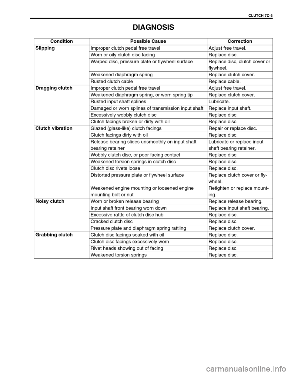
DIAGNOSIS
Condition Possible Cause Correction
Slipping
Improper clutch pedal free travel Adjust free travel.
Worn or oily clutch disc facing Replace disc.
Warped disc, pressure plate or flywheel surface Replace disc, clutch cover or
flywheel.
Weakened diaphragm spring Replace clutch cover.
Rusted clutch cable Replace cable.
Dragging clutch
Improper clutch pedal free travel Adjust free travel.
Weakened diaphragm spring, or worn spring tip Replace clutch cover.
Rusted input shaft splines Lubricate.
Damaged or worn splines of transmission input shaft Replace input shaft.
Excessively wobbly clutch disc Replace disc.
Clutch facings broken or dirty with oil Replace disc.
Clutch vibration
Glazed (glass-like) clutch facings Repair or replace disc.
Clutch facings dirty with oil Replace disc.
Release bearing slides unsmoothly on input shaft
bearing retainerLubricate or replace input
shaft bearing retainer.
Wobbly clutch disc, or poor facing contact Replace disc.
Weakened torsion springs in clutch disc Replace disc.
Clutch disc rivets loose Replace disc.
Distorted pressure plate or flywheel surface Replace clutch cover or fly-
wheel.
Weakened engine mounting or loosened engine
mounting bolt or nutRetighten or replace mount-
ing.
Noisy clutch
Worn or broken release bearing Replace release bearing.
Input shaft front bearing worn down Replace input shaft bearing.
Excessive rattle of clutch disc hub Replace disc.
Cracked clutch disc Replace disc.
Pressure plate and diaphragm spring rattling Replace clutch cover.
Grabbing clutch
Clutch disc facings soaked with oil Replace disc.
Clutch disc facings excessively worn Replace disc.
Rivet heads showing out of facing Replace disc.
Weakened torsion springs Replace disc.
Page 186 of 447

7C-4 CLUTCH
ON-VEHICLE SERVICE
CLUTCH CABLE
REMOVAL
1) Disconnect negative cable at battery.
2) Remove clutch cable joint nut (1).
3) Remove joint pin (2) from clutch release lever (3).
4) Disconnect cable hook (1) from clutch pedal (4).
5) Remove clutch cable (3) from bracket (5) by turning cable
cap (2) about 90° as shown.
1. Clutch cable 6. Pedal bracket
2. Release lever 7. Adjusting bolt
3. Joint pin
: Apply grease 99000-25010 to joint pin.8. Lock nut
4. Joint nut 9. Clutch cable hook
: Apply grease 99000-25010 to cable hook.
5. Clutch pedal Tightening torque
Page 187 of 447

CLUTCH 7C-5
INSPECTION
Inspect clutch cable and replace it for any of the following condi-
tions.
Excessive cable friction
Frayed cable
Bent or kinked cable
Broken boots
Worn end
INSTALLATION
1) Apply grease to cable end hook and also joint pin before
installing cable.
“A” : Grease 99000-25010
2) Hook cable end with pedal by using screwdriver or long nose
pliers from cabin inside, then join inner cable wire joint pin in
release lever.
3) Install clutch cable (2) to bracket (3) by turning cable cap (1)
about 90° as shown.
4) Screw in joint nut and adjust free travel of pedal to specifica-
tion by turning nut.
5) Check clutch for proper function with engine running.
NOTE:
Take care that cable grommet (4) has specific installing
direction as shown in the figure.
Page 188 of 447

7C-6 CLUTCH
CLUTCH PEDAL AND CLUTCH PEDAL BRACKET
1. Clutch cable hook
: Apply grease 99000-25010 to cable
hook.7. Pedal spring
: Apply grease 99000-25010 to inside surface
of spring.13. Adjusting bolt cap
2. Clutch pedal bracket 8. Pedal shaft spacer
: Apply grease 99000-25010 to outside sur-
face of spacer.14. Adjusting bolt
3. Bolt 9. Pedal shaft 15. Lock nut
4.
Nut10.
Clutch pedalTightening torque
5. Pedal shaft nut 11. Pedal pad
6. Pedal bush 12. Pedal return cushion
Page 189 of 447

CLUTCH 7C-7
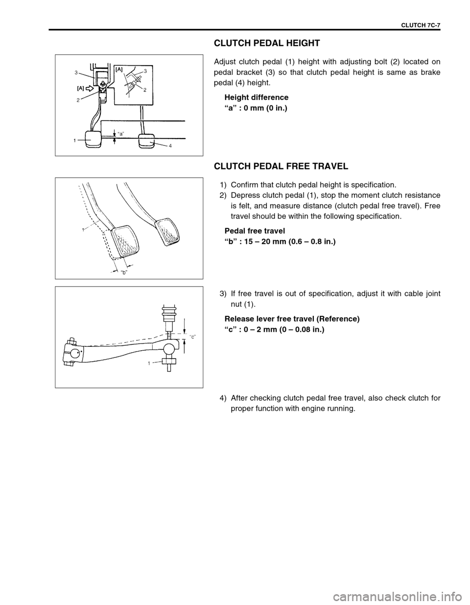
CLUTCH PEDAL HEIGHT
Adjust clutch pedal (1) height with adjusting bolt (2) located on
pedal bracket (3) so that clutch pedal height is same as brake
pedal (4) height.
Height difference
“a” : 0 mm (0 in.)
CLUTCH PEDAL FREE TRAVEL
1) Confirm that clutch pedal height is specification.
2) Depress clutch pedal (1), stop the moment clutch resistance
is felt, and measure distance (clutch pedal free travel). Free
travel should be within the following specification.
Pedal free travel
“b” : 15 – 20 mm (0.6 – 0.8 in.)
3) If free travel is out of specification, adjust it with cable joint
nut (1).
Release lever free travel (Reference)
“c” : 0 – 2 mm (0 – 0.08 in.)
4) After checking clutch pedal free travel, also check clutch for
proper function with engine running.
Page 196 of 447

7C-14 CLUTCH
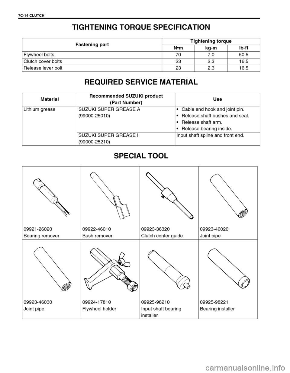
TIGHTENING TORQUE SPECIFICATION
REQUIRED SERVICE MATERIAL
SPECIAL TOOL
Fastening partTightening torque
Nm kg-m lb-ft
Flywheel bolts 70 7.0 50.5
Clutch cover bolts 23 2.3 16.5
Release lever bolt 23 2.3 16.5
MaterialRecommended SUZUKI product
(Part Number)Use
Lithium grease SUZUKI SUPER GREASE A
(99000-25010)Cable end hook and joint pin.
Release shaft bushes and seal.
Release shaft arm.
Release bearing inside.
SUZUKI SUPER GREASE I
(99000-25210)Input shaft spline and front end.
09921-26020 09922-46010 09923-36320 09923-46020
Bearing remover Bush remover Clutch center guide Joint pipe
09923-46030 09924-17810 09925-98210 09925-98221
Joint pipe Flywheel holder Input shaft bearing
installerBearing installer