relay SUZUKI SWIFT 2000 1.G Transmission Service User Guide
[x] Cancel search | Manufacturer: SUZUKI, Model Year: 2000, Model line: SWIFT, Model: SUZUKI SWIFT 2000 1.GPages: 447, PDF Size: 10.54 MB
Page 257 of 447

BODY ELECTRICAL SYSTEM 8-13
TURN SIGNAL AND HAZARD RELAY
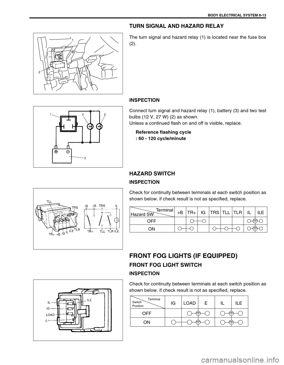
The turn signal and hazard relay (1) is located near the fuse box
(2).
INSPECTION
Connect turn signal and hazard relay (1), battery (3) and two test
bulbs (12 V, 27 W) (2) as shown.
Unless a continued flash on and off is visible, replace.
Reference flashing cycle
: 60 - 120 cycle/minute
HAZARD SWITCH
INSPECTION
Check for continuity between terminals at each switch position as
shown below. if check result is not as specified, replace.
FRONT FOG LIGHTS (IF EQUIPPED)
FRONT FOG LIGHT SWITCH
INSPECTION
Check for continuity between terminals at each switch position as
shown below. if check result is not as specified, replace.
1
2
Hazard SWTerminal
OFF
ON+B TR+ IG TRS TLL TLR IL ILE
Switch
PositionTerminal
ONIG LOAD E IL ILE
OFF
Page 266 of 447

8-22 BODY ELECTRICAL SYSTEM
INSPECTION
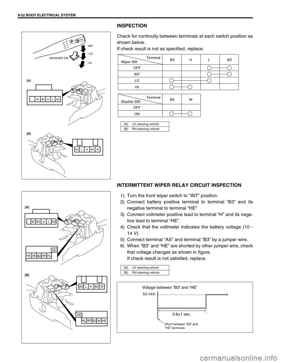
Check for continuity between terminals at each switch position as
shown below.
If check result is not as specified, replace.
INTERMITTENT WIPER RELAY CIRCUIT INSPECTION
1) Turn the front wiper switch to “INT” position.
2) Connect battery positive terminal to terminal “B3” and its
negative terminal to terminal “HE”
3) Connect voltmeter positive lead to terminal “H” and its nega-
tive lead to terminal “HE”.
4) Check that the voltmeter indicates the battery voltage (10 -
14 V).
5) Connect terminal “AS” and terminal “B3” by a jumper wire.
6) When “B3” and “HE” are shorted by other jumper wire, check
that voltage changes as shown in figure.
If check result is not satisfied, replace.
[A] : LH steering vehicle
[B] : RH steering vehicle
INT
WASHER ONLO
[A]
[B]HI
AS AS
L L
H H
B3 B3
W W
HI LO INT OFF
PULL
Terminal
Wiper SW
OFF
INT
LOB3 H L AS
HI
Terminal
Washer SW
OFF
ONB3 W
[A] : LH steering vehicle
[B] : RH steering vehicle
AS L H B3 W
HU
HL RF B2 M HE
AS
L
H B3
W
HU
HL RF
B2 M HE [A]
[B]
10-14V Voltage between “B3” and “HE”
3.8±1 sec.
Short between “B3” and
“HE” terminals
Page 281 of 447

IMMOBILIZER CONTROL SYSTEM 8G-3
WIRING CIRCUIT
1. Immobilizer Control Module 4. Ignition switch 7. Data link connector
2. ECM 5. Fuse 8. To ABS control module, SDM and TCM
3. Main relay 6. Main fuse 9. Immobilizer indicator lamp
BRN/WHT
BLK/RED
BLK/WHT
PNK
BLK/RED
BLK/WHT
BLK
BLK
BLK/ORG
BLK/ORG
BLU
YEL
YEL
BLK/YEL
6
G02-7 G02-5
C42-2
C42-1
C42-3 C41-10
C41-5/6
G02-6
G02-12
G06-4
G06-3
G06-1G06-2
3
45 5
2
8
97
1
BB
BB
Page 288 of 447

8G-10 IMMOBILIZER CONTROL SYSTEM
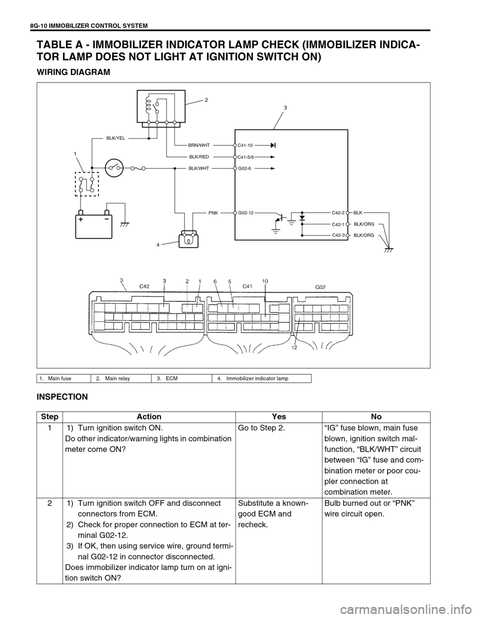
TABLE A - IMMOBILIZER INDICATOR LAMP CHECK (IMMOBILIZER INDICA-
TOR LAMP DOES NOT LIGHT AT IGNITION SWITCH ON)
WIRING DIAGRAM
INSPECTION
1. Main fuse 2. Main relay 3. ECM 4. Immobilizer indicator lamp
BRN/WHT
BLK/RED
BLK/WHT
PNKBLK
BLK/ORG
BLK/ORG
BLK/YEL
C42-2
C42-1
C42-3 C41-10
C41-5/6
G02-6
G02-12
4
1
2
3
Step Action Yes No
1 1) Turn ignition switch ON.
Do other indicator/warning lights in combination
meter come ON?Go to Step 2.“IG” fuse blown, main fuse
blown, ignition switch mal-
function, “BLK/WHT” circuit
between “IG” fuse and com-
bination meter or poor cou-
pler connection at
combination meter.
2 1) Turn ignition switch OFF and disconnect
connectors from ECM.
2) Check for proper connection to ECM at ter-
minal G02-12.
3) If OK, then using service wire, ground termi-
nal G02-12 in connector disconnected.
Does immobilizer indicator lamp turn on at igni-
tion switch ON?Substitute a known-
good ECM and
recheck.Bulb burned out or “PNK”
wire circuit open.
Page 289 of 447

IMMOBILIZER CONTROL SYSTEM 8G-11
TABLE B - IMMOBILIZER INDICATOR LAMP CHECK (IMMOBILIZER INDICA-
TOR LAMP REMAINS ON AFTER ENGINE STARTS)
WIRING DIAGRAM
INSPECTION
1. Main fuse 2. Main relay 3. ECM 4. Immobilizer indicator lamp
BRN/WHT
BLK/RED
BLK/WHT
PNKBLK
BLK/ORG
BLK/ORG
BLK/YEL
C42-2
C42-1
C42-3 C41-10
C41-5/6
G02-6
G02-12
4
1
2
3
Step Action Yes No
1 1) With ignition switch OFF, disconnect cou-
plers from ECM.
Does immobilizer indicator lamp turn ON at
ignition switch ON?“PNK” wire shorted to
ground circuit.Substitute a known-good
ECM and recheck.
Page 293 of 447

IMMOBILIZER CONTROL SYSTEM 8G-15
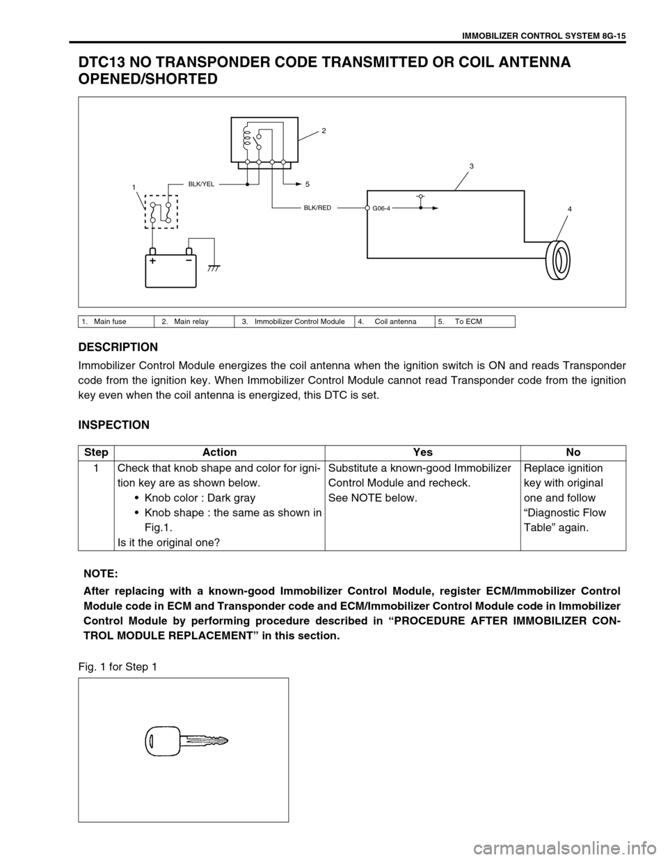
DTC13 NO TRANSPONDER CODE TRANSMITTED OR COIL ANTENNA
OPENED/SHORTED
DESCRIPTION
Immobilizer Control Module energizes the coil antenna when the ignition switch is ON and reads Transponder
code from the ignition key. When Immobilizer Control Module cannot read Transponder code from the ignition
key even when the coil antenna is energized, this DTC is set.
INSPECTION
Fig. 1 for Step 1
1. Main fuse 2. Main relay 3. Immobilizer Control Module 4. Coil antenna 5. To ECM
BLK/RED
BLK/YEL
G06-4
2
3
4 5
1
Step Action Yes No
1 Check that knob shape and color for igni-
tion key are as shown below.
Knob color : Dark gray
Knob shape : the same as shown in
Fig.1.
Is it the original one?Substitute a known-good Immobilizer
Control Module and recheck.
See NOTE below.Replace ignition
key with original
one and follow
“Diagnostic Flow
Table” again.
NOTE:
After replacing with a known-good Immobilizer Control Module, register ECM/Immobilizer Control
Module code in ECM and Transponder code and ECM/Immobilizer Control Module code in Immobilizer
Control Module by performing procedure described in “PROCEDURE AFTER IMMOBILIZER CON-
TROL MODULE REPLACEMENT” in this section.