wiring SUZUKI SWIFT 2000 1.G Transmission Service Workshop Manual
[x] Cancel search | Manufacturer: SUZUKI, Model Year: 2000, Model line: SWIFT, Model: SUZUKI SWIFT 2000 1.GPages: 447, PDF Size: 10.54 MB
Page 1 of 447
MANUAL TRANSMISSION 7A-1
6F1
6F2
6G
6H
6K
7A1
7B1
7C1
7A
7E
7F
8A
8B
8C
8D
8E
9
10
10A
10B
SECTION 7A
MANUAL TRANSMISSION
CONTENTS
GENERAL DESCRIPTION .............................. 7A-2
CONSTRUCTION AND SERVICING ........... 7A-2
TRANSMISSION FOR 2WD MODEL....... 7A-3
TRANSMISSION FOR 4WD MODEL....... 7A-4
DIAGNOSIS ..................................................... 7A-5
ON-VEHICLE SERVICE .................................. 7A-5
OIL CHANGE ............................................... 7A-6
DIFFERENTIAL SIDE OIL SEAL ................. 7A-6
GEAR SHIFT CONTROL LEVER AND
CABLE ......................................................... 7A-8
VEHICLE SPEED SENSOR (VSS) ............ 7A-10
UNIT REPAIR OVERHAUL ........................... 7A-11
TRANSMISSION UNIT............................... 7A-11
TRASMISSION CASE ................................ 7A-12
INPUT & COUNTER SHAFT...................... 7A-13
GEAR SHIFTER & DIFFERENTIAL ........... 7A-14
TRANSMISSION UNIT............................... 7A-16
UNIT DISASSEMBLY ................................ 7A-17
FIFTH GEARS........................................ 7A-17GEAR SHIFTER, INPUT SHAFT AND
COUNTER SHAFT................................. 7A-19
RIGHT CASE ......................................... 7A-20
SUB ASSEMBLY SERVICE ...................... 7A-21
RIGHT CASE ......................................... 7A-21
LEFT CASE............................................ 7A-21
INPUT SHAFT ASSEMBLY ................... 7A-22
COUNTER SHAFT ASSEMBLY ............ 7A-25
GEAR SHIFTER..................................... 7A-29
DIFFERENTIAL ASSEMBLY ................. 7A-30
UNIT ASSEMBLY ...................................... 7A-33
DIFFERENTIAL TO LEFT CASE ........... 7A-33
FIFTH GEARS ....................................... 7A-35
GEAR SHIFT AND SELECT SHAFT
ASSEMBLY ............................................ 7A-38
TIGHTENING TORQUE SPECIFICATION.... 7A-39
REQUIRED SERVICE MATERIAL................ 7A-40
SPECIAL TOOL ............................................ 7A-40
WARNING:
For vehicles equipped with Supplemental Restraint (Air Bag) System :
• Service on and around the air bag system components or wiring must be performed only by an
authorized SUZUKI dealer. Refer to “Air Bag System Components and Wiring Location View” under
“General Description” in air bag system section in order to confirm whether you are performing ser-
vice on or near the air bag system components or wiring. Please observe all WARNINGS and “Ser-
vice Precautions” under “On-Vehicle Service” in air bag system section before performing service
on or around the air bag system components or wiring. Failure to follow WARNINGS could result in
unintentional activation of the system or could render the system inoperative. Either of these two
conditions may result in severe injury.
Technical service work must be started at least 90 seconds after the ignition switch is turned to the
“LOCK” position and the negative cable is disconnected from the battery. Otherwise, the system
may be activated by reserve energy in the Sensing and Diagnostic Module (SDM).
Page 16 of 447
7A-16 MANUAL TRANSMISSION
TRANSMISSION UNIT
DISMOUNTING
Under Hood
1) Disconnect negative cable at battery.
2) Undo wiring harness clamps, disconnect backup lamp switch
coupler, VSS coupler and ground cable.
3) Disconnect clutch cable from clutch release lever and
bracket.
4) Disconnect gear shift and select control cables.
5) Remove water pipe bracket bolts from transmission.
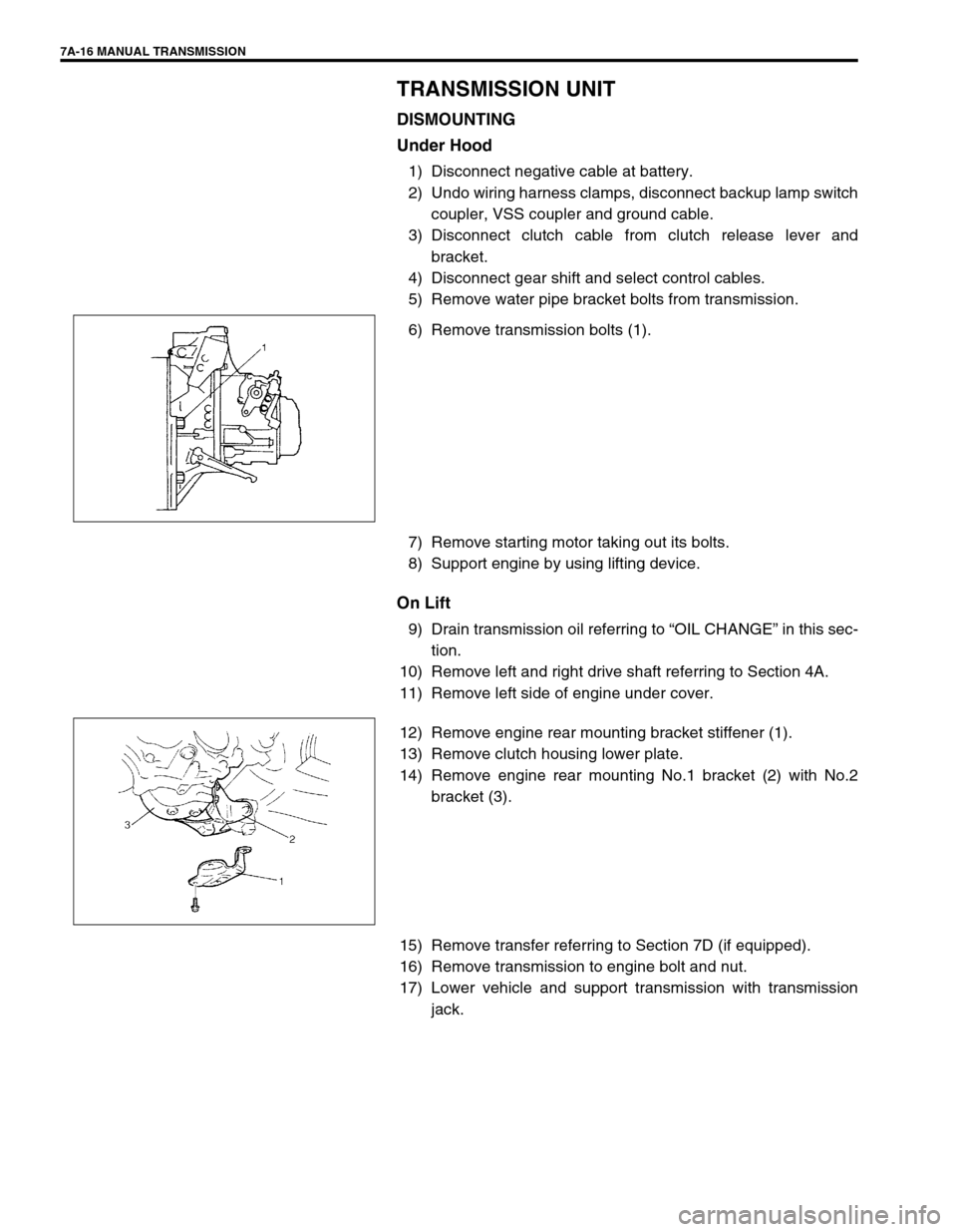
6) Remove transmission bolts (1).
7) Remove starting motor taking out its bolts.
8) Support engine by using lifting device.
On Lift
9) Drain transmission oil referring to “OIL CHANGE” in this sec-
tion.
10) Remove left and right drive shaft referring to Section 4A.
11) Remove left side of engine under cover.
12) Remove engine rear mounting bracket stiffener (1).
13) Remove clutch housing lower plate.
14) Remove engine rear mounting No.1 bracket (2) with No.2
bracket (3).
15) Remove transfer referring to Section 7D (if equipped).
16) Remove transmission to engine bolt and nut.
17) Lower vehicle and support transmission with transmission
jack.
Page 17 of 447
MANUAL TRANSMISSION 7A-17
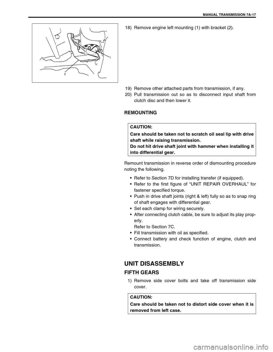
18) Remove engine left mounting (1) with bracket (2).
19) Remove other attached parts from transmission, if any.
20) Pull transmission out so as to disconnect input shaft from
clutch disc and then lower it.
REMOUNTING
Remount transmission in reverse order of dismounting procedure
noting the following.
Refer to Section 7D for installing transfer (if equipped).
Refer to the first figure of “UNIT REPAIR OVERHAUL” for
fastener specified torque.
Push in drive shaft joints (right & left) fully so as to snap ring
of shaft engages with differential gear.
Set each clamp for wiring securely.
After connecting clutch cable, be sure to adjust its play prop-
erly.
Refer to Section 7C.
Fill transmission with oil as specified.
Connect battery and check function of engine, clutch and
transmission.
UNIT DISASSEMBLY
FIFTH GEARS
1) Remove side cover bolts and take off transmission side
cover.
CAUTION:
Care should be taken not to scratch oil seal lip with drive
shaft while raising transmission.
Do not hit drive shaft joint with hammer when installing it
into differential gear.
CAUTION:
Care should be taken not to distort side cover when it is
removed from left case.
Page 43 of 447
AUTOMATIC TRANSMISSION (4 A/T) 7B-1
6F1
6F2
6G
6H
6K
7A
7A1
7C1
7D
7B
7F
8A
8B
8C
8D
8E
9
10
10A
10B
SECTION 7B
AUTOMATIC TRANSMISSION (4 A/T)
CONTENTS
GENERAL DESCRIPTION ...............................7B-3
ELECTRONIC SHIFT CONTROL SYSTEM . 7B-6
TRANSMISSION CONTROL MODULE
(TCM) ........................................................ 7B-7
FAIL SAFE FUNCTION ............................. 7B-8
CHANGE MECHANISM .......................... 7B-10
AUTOMATIC GEAR SHIFT DIAGRAM ... 7B-11
DIAGNOSIS ....................................................7B-13
AUTOMATIC TRANSMISSION
DIAGNOSTIC FLOW TABLE ...................... 7B-13
TROUBLE DIAGNOSIS TABLE .................. 7B-18
STALL TEST ........................................... 7B-20
TIME LAG TEST ..................................... 7B-21
LINE PRESSURE TEST ......................... 7B-22
ENGINE BRAKE TEST ........................... 7B-23
“P” RANGE TEST.................................... 7B-23
ELECTRONIC CONTROL SYSTEM
DIAGNOSIS ................................................ 7B-24
PRECAUTIONS IN DIAGNOSING
TROUBLES ............................................. 7B-24
DTC CHECK ........................................... 7B-25
DTC CLEARANCE .................................. 7B-27
DTC TABLE............................................. 7B-28
TCM POWER AND GROUND CIRCUIT
CHECK .................................................... 7B-30
DTC P0715 (DTC NO.14) INPUT/
TURBINE SPEED SENSOR CIRCUIT
MALFUNCTION ...................................... 7B-31
DTC P0730 (DTC NO. 18) INCORRECT
GEAR RATIO .......................................... 7B-33
DTC P0753 (DTC NO.21/22) SHIFT
SOLENOID-A (NO.1) ELECTRICAL ....... 7B-35DTC P0758 (DTC NO.23/24) SHIFT
SOLENOID-B (NO.2) ELECTRICAL ....... 7B-35
DTC P0743 (DTC NO.25/26) TCC
(LOCK-UP CLUTCH) SYSTEM
ELECTRICAL .......................................... 7B-35
DTC P0741 (DTC NO.29) TCC
(LOCK-UP) SOLENOID
PERFORMANCE OR STUCK OFF ........ 7B-37
DTC P0720 (DTC NO. 31) OUTPUT
SHAFT SPEED SENSOR CIRCUIT
MALFUNCTION ...................................... 7B-38
DTC P1700 (DTC NO.32/33)
THROTTLE POSITION SIGNAL INPUT
MALFUNCTION ...................................... 7B-41
DTC P0705 (DTC NO.34)
TRANSMISSION RANGE SENSOR
(SWITCH) CIRCUIT MALFUNCTION ..... 7B-43
DTC P0725 (DTC NO.35) ENGINE
SPEED INPUT CIRCUIT
MALFUNCTION ...................................... 7B-45
DTC P0710 (DTC No.36/38)
TRANSMISSION TEMPERATURE
SENSOR CIRCUIT MALFUNCTION ...... 7B-47
DTC P0763 (DTC NO.43) SHIFT
SOLENOID-C (NO.3) ELECTRICAL ....... 7B-49
DTC P0768 (DTC NO.45) SHIFT
SOLENOID-B (NO.4) ELECTRICAL ....... 7B-49
DTC P0773 (DTC NO.48) SHIFT
SOLENOID-E (NO.5) ELECTRICAL ....... 7B-49
DTC P1709 (DTC NO.51) ENGINE
COOLANT TEMPERATURE/BAROMETRIC
PRESSURE SIGNAL CIRCUIT............... 7B-51 WARNING:
For vehicles equipped with Supplemental Restraint (Air Bag) System :
Service on and around the air bag system components or wiring must be performed only by an
authorized SUZUKI dealer. Refer to “Air Bag System Components and Wiring Location View” under
“General Description” in air bag system section in order to confirm whether you are performing ser-
vice on or near the air bag system components or wiring. Please observe all WARNINGS and “Ser-
vice Precautions” under “On-Vehicle Service” in air bag system section before performing service
on or around the air bag system components or wiring. Failure to follow WARNINGS could result in
unintentional activation of the system or could render the system inoperative. Either of these two
conditions may result in severe injury.
Technical service work must be started at least 90 seconds after the ignition switch is turned to the
“LOCK” position and the negative cable is disconnected from the battery. Otherwise, the system
may be activated by reserve energy in the Sensing and Diagnostic Module (SDM).
Page 95 of 447
AUTOMATIC TRANSMISSION (4 A/T) 7B-53
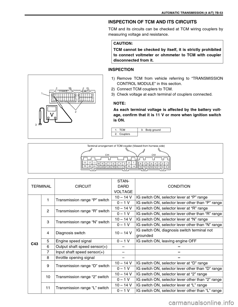
INSPECTION OF TCM AND ITS CIRCUITS
TCM and its circuits can be checked at TCM wiring couplers by
measuring voltage and resistance.
INSPECTION
1) Remove TCM from vehicle referring to “TRANSMISSION
CONTROL MODULE” in this section.
2) Connect TCM couplers to TCM.
3) Check voltage at each terminal of couplers connected.CAUTION:
TCM cannot be checked by itself, it is strictly prohibited
to connect voltmeter or ohmmeter to TCM with coupler
disconnected from it.
NOTE:
As each terminal voltage is affected by the battery volt-
age, confirm that it is 11 V or more when ignition switch
is ON.
1. TCM 3. Body ground
2. Couplers
TERMINAL CIRCUITSTAN-
DARD
VOLTAGECONDITION
C431 Transmission range “P” switch10 – 14 V IG switch ON, selector lever at “P” range
0 – 1 V IG switch ON, selector lever other than “P” range
2 Transmission range “R” switch10 – 14 V IG switch ON, selector lever at “R” range
0 – 1 V IG switch ON, selector lever other than “R” range
3 Transmission range “N” switch10 – 14 V IG switch ON, selector lever at “N” range
0 – 1 V IG switch ON, selector lever other than “N” range
4 Diagnosis switch 10 – 14 VIG switch ON, diagnosis switch terminal not
grounded
5 Engine speed signal 0 – 1 V IG switch ON, leaving engine OFF
6 Output shaft speed sensor(+)––
7 Input shaft speed sensor(+)––
8 throttle opening signal––
9 Transmission range “D” switch10 – 14 V IG switch ON, selector lever at “D” range
0 – 1 V IG switch ON, selector lever other than “D” range
10 Transmission range “2” switch10 – 14 V IG switch ON, selector lever at “2” range
0 – 1 V IG switch ON, selector lever other than “2” range
11 Transmission range “L” switch10 – 14 V IG switch ON, selector lever at “L” range
0 – 1 V IG switch ON, selector lever other than “L” range
Page 183 of 447

CLUTCH 7C-1
6F1
6F2
6G
6H
6K
7A1
7B1
7C1
7D
7E
7C
8A
8B
8C
8D
8E
9
10
10A
10B
SECTION 7C
CLUTCH
CONTENTS
GENERAL DESCRIPTION .............................. 7C-2
DIAGNOSIS ..................................................... 7C-3
ON-VEHICLE SERVICE .................................. 7C-4
CLUTCH CABLE .......................................... 7C-4
CLUTCH PEDAL AND CLUTCH PEDAL
BRACKET .................................................... 7C-6
CLUTCH PEDAL HEIGHT ....................... 7C-7
CLUTCH PEDAL FREE TRAVEL ............ 7C-7UNIT REPAIR OVERHAUL ............................. 7C-8
CLUTCH COVER, CLUTCH DISC AND
FLYWHEEL.................................................. 7C-8
CLUTCH RELEASE SYSTEM ................... 7C-11
TIGHTENING TORQUE SPECIFICATION.... 7C-14
REQUIRED SERVICE MATERIAL................ 7C-14
SPECIAL TOOL ............................................ 7C-14
WARNING:
For vehicles equipped with Supplemental Restraint (Air Bag) System:
Service on and around the air bag system components or wiring must be performed only by an
authorized SUZUKI dealer. Refer to “Air Bag System Components and Wiring Location View” under
“General Description” in air bag system section in order to confirm whether you are performing ser-
vice on or near the air bag system components or wiring. Please observe all WARNINGS and “Ser-
vice Precautions” under “On-Vehicle Service” in air bag system section before performing service
on or around the air bag system components or wiring. Failure to follow WARNINGS could result in
unintentional activation of the system or could render the system inoperative. Either of these two
conditions may result in severe injury.
Technical service work must be started at least 90 seconds after the ignition switch is turned to the
“LOCK” position and the negative cable is disconnected from the battery. Otherwise, the system
may be activated by reserve energy in the Sensing and Diagnostic Module (SDM).
Page 245 of 447
BODY ELECTRICAL SYSTEM 8-1
6F1
6F2
6G
6H
6K
7A
7A1
7B1
7C1
7D
7E
7F
8A
8
8D
8E
9
10
10A
10B
SECTION 8
BODY ELECTRICAL SYSTEM
CONTENTS
DIAGNOSIS ........................................................ 8-3
HEADLIGHT .................................................... 8-3
HEADLIGHTS WITH LEVELING SYSTEM
(IF EQUIPPED) ............................................... 8-3
TURN SIGNAL AND HAZARD WARNING
LIGHT .............................................................. 8-3
CLEARANCE, TAIL AND LICENSE
PLATE LIGHT ................................................. 8-4
BACK-UP LIGHT ............................................. 8-4
BRAKE LIGHT ................................................ 8-4
FRONT FOG LIGHT (IF EQUIPPED) ............. 8-4
REAR FOG LIGHT (IF EQUIPPED) ................ 8-4
SPEEDOMETER AND VSS ............................ 8-5
FUEL METER AND FUEL LEVEL SENSOR
(GAUGE UNIT) ............................................... 8-5
ENGINE COOLANT TEMPERATURE (ECT)
METER AND ECT SENSOR ........................... 8-5
OIL PRESSURE WARNING LIGHT ................ 8-5
BRAKE AND PARKING BRAKE WARNING
LIGHT .............................................................. 8-6
REAR WINDOW DEFOGGER ........................ 8-6
WIPERS AND WASHERS .............................. 8-6
FRONT WIPER AND WASHER .................. 8-6
REAR WIPER AND WASHER (IF
EQUIPPED)................................................. 8-6
POWER WINDOW CONTROL SYSTEM
(IF EQUIPPED) ............................................... 8-7
CIGARETTE LIGHTER ................................... 8-7
POWER DOOR LOCK CONTROL SYSTEM
(IF EQUIPPED) ............................................... 8-7
KEYLESS ENTRY SYSTEM (IF
EQUIPPED) .................................................... 8-7POWER DOOR MIRROR CONTROL
SYSTEM (IF EQUIPPED) ............................... 8-8
INTERIOR LIGHT ........................................... 8-8
HORN ............................................................. 8-8
IGNITION KEY REMAINDER (IF EQUIPPED)
AND LIGHT REMAINDER WARNING
BUZZER.......................................................... 8-8
SEAT BELT WARNING LIGHT (IF
EQUIPPED) .................................................... 8-8
FRONT SEAT HEATER (IF EQUIPPED) ....... 8-9
ON-VEHICLE SERVICE ..................................... 8-9
CAUTIONS IN SERVICING ............................ 8-9
HEADLIGHT ................................................... 8-9
HEADLIGHT SWITCH ................................ 8-9
HEADLIGHT ASSEMBLY ......................... 8-10
HEADLIGHT BULB ................................... 8-10
HEADLIGHT AIMING ADJUSTMENT
WITH SCREEN ......................................... 8-11
HEADLIGHT LEVELING SWITCH (IF
EQUIPPED) .............................................. 8-12
TURN SIGNAL AND HAZARD WARNING
LIGHTS ......................................................... 8-12
TURN SIGNAL LIGHT SWITCH ............... 8-12
REMOVAL AND INSTALLATION ............. 8-12
TURN SIGNAL AND HAZARD RELAY ..... 8-13
HAZARD SWITCH .................................... 8-13
FRONT FOG LIGHTS (IF EQUIPPED)......... 8-13
FRONT FOG LIGHT SWITCH .................. 8-13
REAR FOG LIGHT (IF EQUIPPED) ............. 8-14
REAR FOG LIGHT SWITCH..................... 8-14
IGNITION SWITCH ....................................... 8-14
COMBINATION METER ............................... 8-15 WARNING:
For vehicles equipped with Supplemental Restraint (Air Bag) System :
Service on and around the air bag system components or wiring must be performed only by an
authorized SUZUKI dealer. Refer to “Air Bag System Components and Wiring Location View” under
“General Description” in air bag system section in order to confirm whether you are performing ser-
vice on or near the air bag system components or wiring. Please observe all WARNINGS and “Ser-
vice Precautions” under “On-Vehicle Service” in air bag system section before performing service
on or around the air bag system components or wiring. Failure to follow WARNINGS could result in
unintentional activation of the system or could render the system inoperative. Either of these two
conditions may result in severe injury.
Technical service work must be started at least 90 seconds after the ignition switch is turned to the
“LOCK” position and the negative cable is disconnected from the battery. Otherwise, the system
may be activated by reserve energy in the Sensing and Diagnostic Module (SDM).
Page 247 of 447
BODY ELECTRICAL SYSTEM 8-3
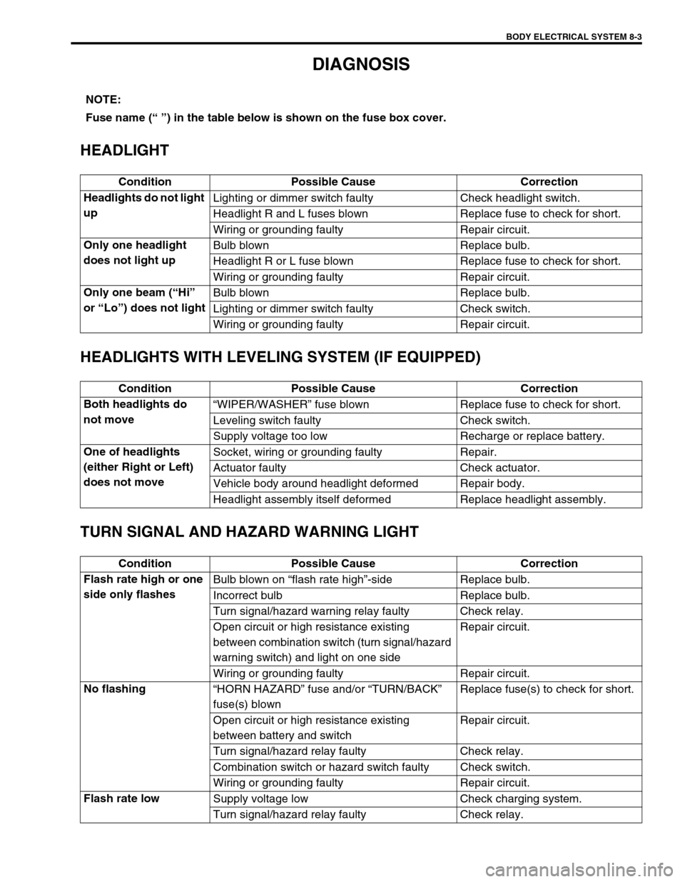
DIAGNOSIS
HEADLIGHT
HEADLIGHTS WITH LEVELING SYSTEM (IF EQUIPPED)
TURN SIGNAL AND HAZARD WARNING LIGHT
NOTE:
Fuse name (“ ”) in the table below is shown on the fuse box cover.
Condition Possible Cause Correction
Headlights do not light
upLighting or dimmer switch faulty Check headlight switch.
Headlight R and L fuses blown Replace fuse to check for short.
Wiring or grounding faulty Repair circuit.
Only one headlight
does not light upBulb blown Replace bulb.
Headlight R or L fuse blown Replace fuse to check for short.
Wiring or grounding faulty Repair circuit.
Only one beam (“Hi”
or “Lo”) does not lightBulb blown Replace bulb.
Lighting or dimmer switch faulty Check switch.
Wiring or grounding faulty Repair circuit.
Condition Possible Cause Correction
Both headlights do
not move“WIPER/WASHER” fuse blown Replace fuse to check for short.
Leveling switch faulty Check switch.
Supply voltage too low Recharge or replace battery.
One of headlights
(either Right or Left)
does not moveSocket, wiring or grounding faulty Repair.
Actuator faulty Check actuator.
Vehicle body around headlight deformed Repair body.
Headlight assembly itself deformed Replace headlight assembly.
Condition Possible Cause Correction
Flash rate high or one
side only flashesBulb blown on “flash rate high”-side Replace bulb.
Incorrect bulb Replace bulb.
Turn signal/hazard warning relay faulty Check relay.
Open circuit or high resistance existing
between combination switch (turn signal/hazard
warning switch) and light on one sideRepair circuit.
Wiring or grounding faulty Repair circuit.
No flashing
“HORN HAZARD” fuse and/or “TURN/BACK”
fuse(s) blownReplace fuse(s) to check for short.
Open circuit or high resistance existing
between battery and switchRepair circuit.
Turn signal/hazard relay faulty Check relay.
Combination switch or hazard switch faulty Check switch.
Wiring or grounding faulty Repair circuit.
Flash rate low
Supply voltage low Check charging system.
Turn signal/hazard relay faulty Check relay.
Page 248 of 447
8-4 BODY ELECTRICAL SYSTEM
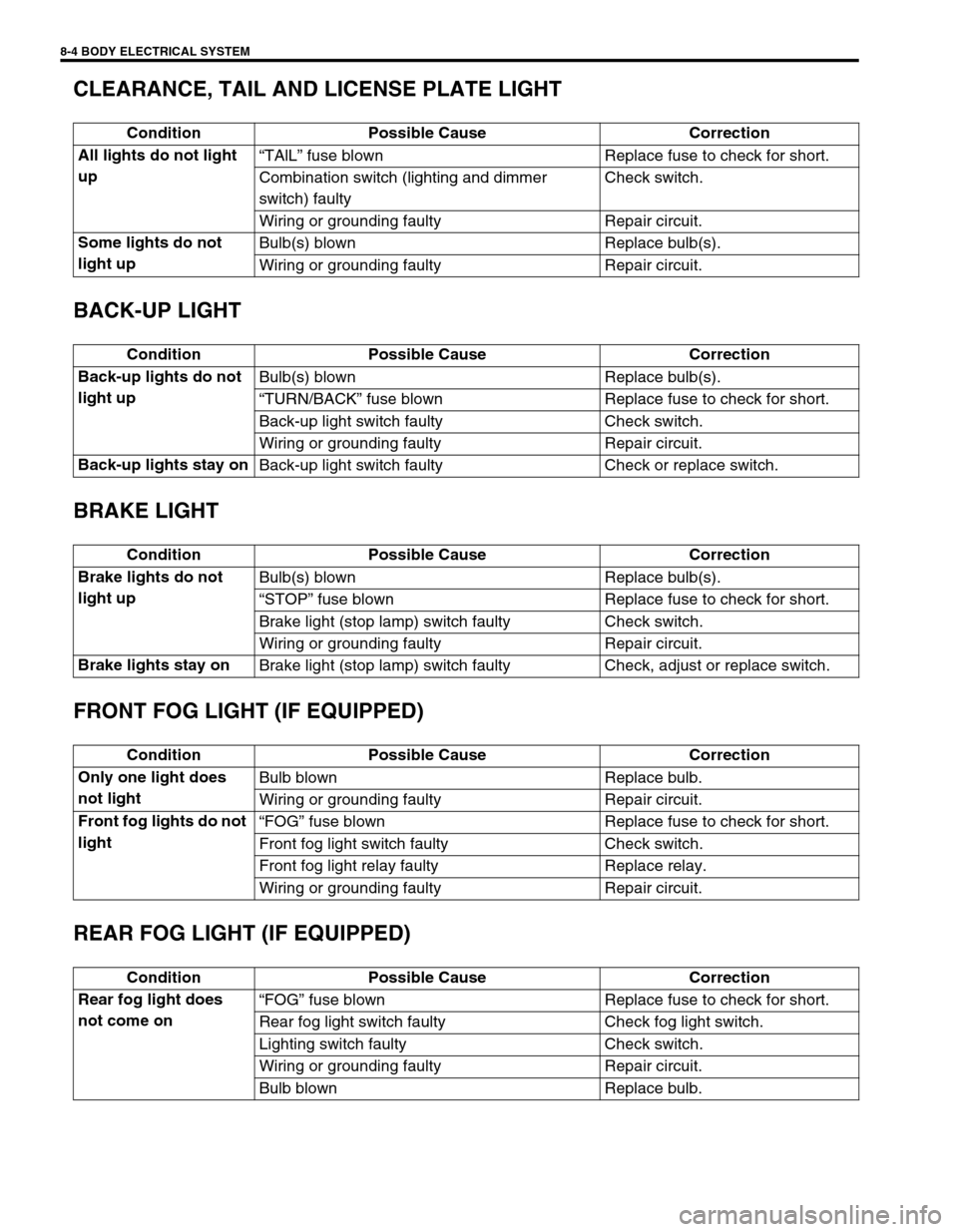
CLEARANCE, TAIL AND LICENSE PLATE LIGHT
BACK-UP LIGHT
BRAKE LIGHT
FRONT FOG LIGHT (IF EQUIPPED)
REAR FOG LIGHT (IF EQUIPPED)
Condition Possible Cause Correction
All lights do not light
up“TAlL” fuse blown Replace fuse to check for short.
Combination switch (lighting and dimmer
switch) faultyCheck switch.
Wiring or grounding faulty Repair circuit.
Some lights do not
light upBulb(s) blown Replace bulb(s).
Wiring or grounding faulty Repair circuit.
Condition Possible Cause Correction
Back-up lights do not
light upBulb(s) blown Replace bulb(s).
“TURN/BACK” fuse blown Replace fuse to check for short.
Back-up light switch faulty Check switch.
Wiring or grounding faulty Repair circuit.
Back-up lights stay on
Back-up light switch faulty Check or replace switch.
Condition Possible Cause Correction
Brake lights do not
light upBulb(s) blown Replace bulb(s).
“STOP” fuse blown Replace fuse to check for short.
Brake light (stop lamp) switch faulty Check switch.
Wiring or grounding faulty Repair circuit.
Brake lights stay on
Brake light (stop lamp) switch faulty Check, adjust or replace switch.
Condition Possible Cause Correction
Only one light does
not lightBulb blown Replace bulb.
Wiring or grounding faulty Repair circuit.
Front fog lights do not
light“FOG” fuse blown Replace fuse to check for short.
Front fog light switch faulty Check switch.
Front fog light relay faulty Replace relay.
Wiring or grounding faulty Repair circuit.
Condition Possible Cause Correction
Rear fog light does
not come on“FOG” fuse blown Replace fuse to check for short.
Rear fog light switch faulty Check fog light switch.
Lighting switch faulty Check switch.
Wiring or grounding faulty Repair circuit.
Bulb blown Replace bulb.
Page 249 of 447
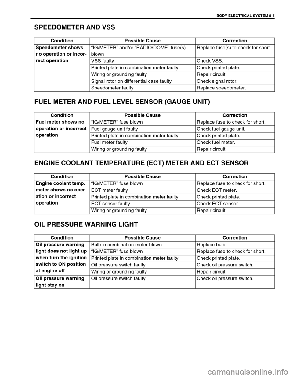
BODY ELECTRICAL SYSTEM 8-5
SPEEDOMETER AND VSS
FUEL METER AND FUEL LEVEL SENSOR (GAUGE UNIT)
ENGINE COOLANT TEMPERATURE (ECT) METER AND ECT SENSOR
OIL PRESSURE WARNING LIGHT
Condition Possible Cause Correction
Speedometer shows
no operation or incor-
rect operation“IG/METER” and/or “RADIO/DOME” fuse(s)
blownReplace fuse(s) to check for short.
VSS faulty Check VSS.
Printed plate in combination meter faulty Check printed plate.
Wiring or grounding faulty Repair circuit.
Signal rotor on differential case faulty Check signal rotor.
Speedometer faulty Replace speedometer.
Condition Possible Cause Correction
Fuel meter shows no
operation or incorrect
operation“IG/METER” fuse blown Replace fuse to check for short.
Fuel gauge unit faulty Check fuel gauge unit.
Printed plate in combination meter faulty Check printed plate.
Fuel meter faulty Check fuel meter.
Wiring or grounding faulty Repair circuit.
Condition Possible Cause Correction
Engine coolant temp.
meter shows no oper-
ation or incorrect
operation“IG/METER” fuse blown Replace fuse to check for short.
ECT meter faulty Check ECT meter.
Printed plate in combination meter faulty Check printed plate.
ECT sensor faulty Check ECT sensor.
Wiring or grounding faulty Repair circuit.
Condition Possible Cause Correction
Oil pressure warning
light does not light up
when turn the ignition
switch to ON position
at engine offBulb in combination meter blown Replace bulb.
“IG/METER” fuse blown Replace fuse to check for short.
Printed plate in combination meter faulty Check printed plate.
Oil pressure switch faulty Check oil pressure switch.
Wiring or grounding faulty Repair circuit.
Oil pressure warning
light stay onOil pressure switch faulty Check oil pressure switch.