warning light SUZUKI SWIFT 2000 1.G Transmission Service User Guide
[x] Cancel search | Manufacturer: SUZUKI, Model Year: 2000, Model line: SWIFT, Model: SUZUKI SWIFT 2000 1.GPages: 447, PDF Size: 10.54 MB
Page 262 of 447

8-18 BODY ELECTRICAL SYSTEM
ECT SENSOR
REMOVAL, INSTALLATION AND INSPECTION
Refer to “ECT SENSOR” in Section 6E1.
OIL PRESSURE WARNING LIGHT
OIL PRESSURE SWITCH
ON-VEHICLE INSPECTION
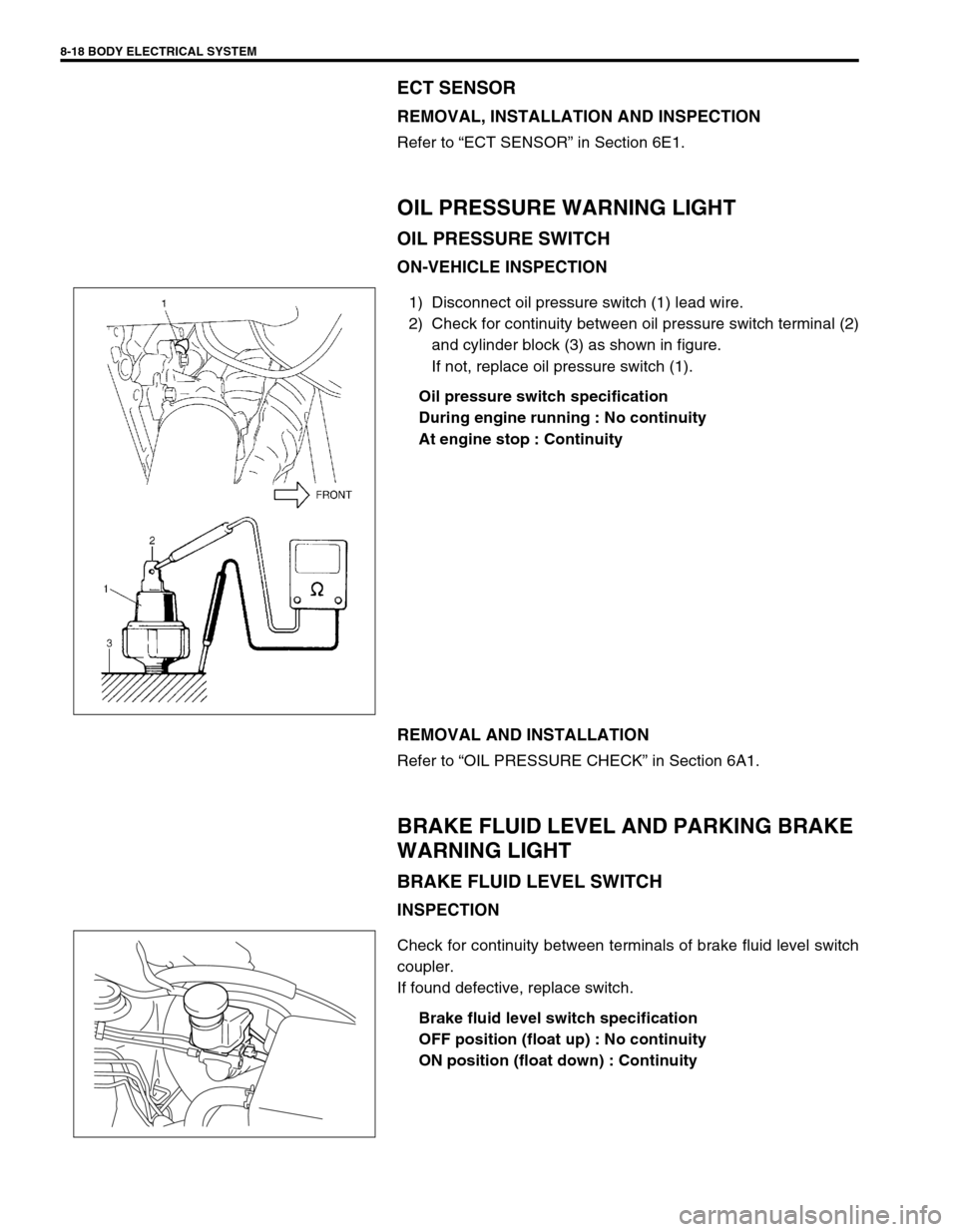
1) Disconnect oil pressure switch (1) lead wire.
2) Check for continuity between oil pressure switch terminal (2)
and cylinder block (3) as shown in figure.
If not, replace oil pressure switch (1).
Oil pressure switch specification
During engine running : No continuity
At engine stop : Continuity
REMOVAL AND INSTALLATION
Refer to “OIL PRESSURE CHECK” in Section 6A1.
BRAKE FLUID LEVEL AND PARKING BRAKE
WARNING LIGHT
BRAKE FLUID LEVEL SWITCH
INSPECTION
Check for continuity between terminals of brake fluid level switch
coupler.
If found defective, replace switch.
Brake fluid level switch specification
OFF position (float up) : No continuity
ON position (float down) : Continuity
Page 269 of 447

BODY ELECTRICAL SYSTEM 8-25
REAR WIPER AND WASHER SWITCH (IF EQUIPPED)
INSPECTION
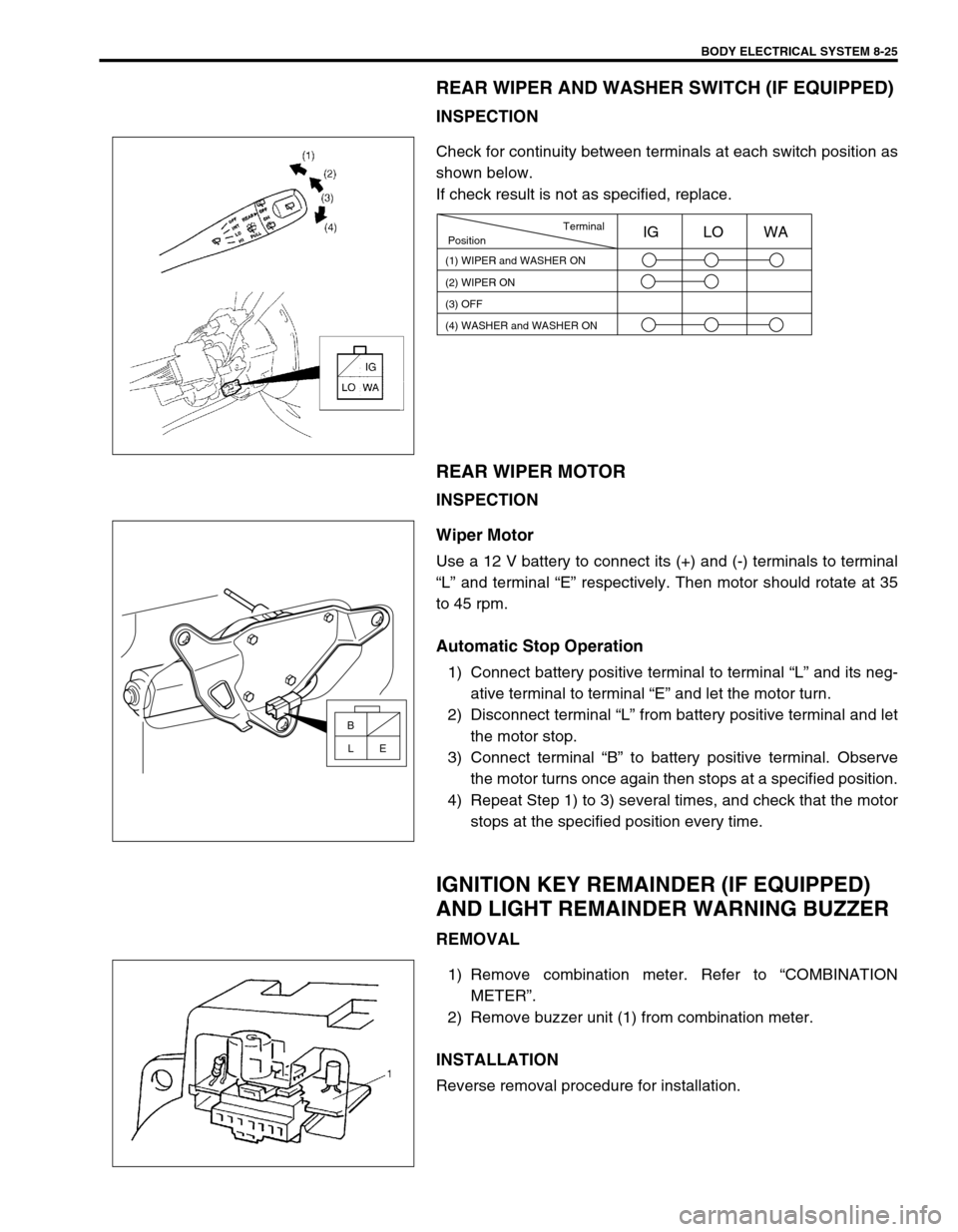
Check for continuity between terminals at each switch position as
shown below.
If check result is not as specified, replace.
REAR WIPER MOTOR
INSPECTION
Wiper Motor
Use a 12 V battery to connect its (+) and (-) terminals to terminal
“L” and terminal “E” respectively. Then motor should rotate at 35
to 45 rpm.
Automatic Stop Operation
1) Connect battery positive terminal to terminal “L” and its neg-
ative terminal to terminal “E” and let the motor turn.
2) Disconnect terminal “L” from battery positive terminal and let
the motor stop.
3) Connect terminal “B” to battery positive terminal. Observe
the motor turns once again then stops at a specified position.
4) Repeat Step 1) to 3) several times, and check that the motor
stops at the specified position every time.
IGNITION KEY REMAINDER (IF EQUIPPED)
AND LIGHT REMAINDER WARNING BUZZER
REMOVAL
1) Remove combination meter. Refer to “COMBINATION
METER”.
2) Remove buzzer unit (1) from combination meter.
INSTALLATION
Reverse removal procedure for installation.
Terminal
Position
(1) WIPER and WASHER ON
(2) WIPER ON
(3) OFFIG LO WA
(4) WASHER and WASHER ON
B
E L
Page 279 of 447

IMMOBILIZER CONTROL SYSTEM 8G-1
6F1
6F2
6G
6H
6K
7A
7A1
7B1
7C1
7D
7E
7F
8A
8B
8C
8D
8G
9
10
10A
10B
SECTION 8G
IMMOBILIZER CONTROL SYSTEM
CONTENTS
GENERAL DESCRIPTION ............................. 8G-2
WIRING CIRCUIT ....................................... 8G-3
ON-BOARD DIAGNOSTIC SYSTEM
(SELF-DIAGNOSIS FUNCTION) ................ 8G-4
DIAGNOSIS .................................................... 8G-5
PRECAUTIONS IN DIAGNOSING
TROUBLES ................................................. 8G-5
PRECAUTIONS IN IDENTIFYING
DIAGNOSTIC TROUBLE CODE............. 8G-5
DIAGNOSTIC FLOW TABLE ...................... 8G-6
DIAGNOSTIC TROUBLE CODE (DTC)
CHECK
(IMMOBILIZER CONTROL MODULE)........ 8G-7
DIAGNOSTIC TROUBLE CODE (DTC)
CHECK (ECM) ............................................ 8G-8
DIAGNOSTIC TROUBLE CODE TABLE .... 8G-9
TABLE A - IMMOBILIZER INDICATOR
LAMP CHECK (IMMOBILIZER INDICATOR
LAMP DOES NOT LIGHT AT IGNITION
SWITCH ON) ............................................ 8G-10
TABLE B - IMMOBILIZER INDICATOR
LAMP CHECK (IMMOBILIZER INDICATOR
LAMP REMAINS ON AFTER ENGINE
STARTS) ................................................... 8G-11
TABLE C - DTC IS NOT OUTPUT FROM
IMMOBILIZER CONTROL MODULE ........ 8G-12
DTC11/32 TRANSPONDER CODE NOT
MATCHED ................................................ 8G-13
DTC31 TRANSPONDER CODE NOT
REGISTERED ........................................... 8G-14
DTC12 FAULT IN IMMOBILIZER
CONTROL MODULE ................................ 8G-14DTC13 NO TRANSPONDER CODE
TRANSMITTED OR COIL ANTENNA
OPENED/SHORTED ................................. 8G-15
DTC21 ECM/IMMOBILIZER CONTROL
MODULE CODE NOT MATCHED
(IMMOBILIZER CONTROL MODULE
SIDE) ......................................................... 8G-16
DTC P1623 ECM/IMMOBILIZER CONTROL
MODULE CODE NOT MATCHED (ECM
SIDE) ......................................................... 8G-16
DTC P1620 ECM/IMMOBILIZER CONTROL
MODULE CODE NOT REGISTERED ....... 8G-16
DTC P1622 FAULT IN ECM ...................... 8G-16
DTC22 IGNITION SWITCH CIRCUIT
OPEN/SHORT ........................................... 8G-17
DTC23 NO ECM/IMMOBILIZER CONTROL
MODULE CODE TRANSMITTED FROM
ECM OR DLC CIRCUIT OPENED/
SHORTED ................................................. 8G-18
DTC P1621 NO ECM/IMMOBILIZER
CONTROL MODULE CODE TRANSMITTED
FROM IMMOBILIZER CONTROL
MODULE OR DLC CIRCUIT OPENED/
SHORTED ................................................. 8G-18
INSPECTION OF ECM, IMMOBILIZER
CONTROL MODULE AND ITS CIRCUIT .. 8G-20
ON-VEHICLE SERVICE ................................ 8G-21
PRECAUTIONS IN HANDLING
IMMOBILIZER CONTROL SYSTEM ......... 8G-21
IMMOBILIZER CONTROL MODULE ......... 8G-22
HOW TO REGISTER IGNITION KEY ........... 8G-23 WARNING:
For vehicles equipped with Supplemental Restraint (Air Bag) System
Service on and around the air bag system components or wiring must be performed only by an
authorized SUZUKI dealer. Refer to “Air Bag System Components and Wiring Location View” under
“General Description” in air bag system section in order to confirm whether you are performing ser-
vice on or near the air bag system components or wiring. Please observe all WARNINGS and “Ser-
vice Precautions” under “On-Vehicle Service” in air bag system section before performing service
on or around the air bag system components or wiring. Failure to follow WARNINGS could result in
unintentional activation of the system or could render the system inoperative. Either of these two
conditions may result in severe injury.
Technical service work must be started at least 90 seconds after the ignition switch is turned to the
“LOCK” position and the negative cable is disconnected from the battery. Otherwise, the system
may be activated by reserve energy in the Sensing and Diagnostic Module (SDM).
Page 288 of 447

8G-10 IMMOBILIZER CONTROL SYSTEM
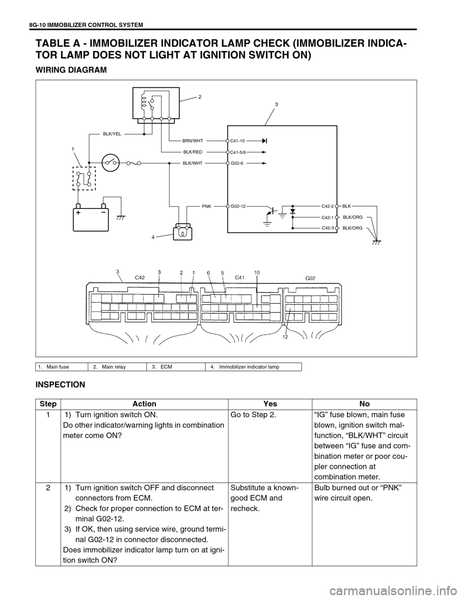
TABLE A - IMMOBILIZER INDICATOR LAMP CHECK (IMMOBILIZER INDICA-
TOR LAMP DOES NOT LIGHT AT IGNITION SWITCH ON)
WIRING DIAGRAM
INSPECTION
1. Main fuse 2. Main relay 3. ECM 4. Immobilizer indicator lamp
BRN/WHT
BLK/RED
BLK/WHT
PNKBLK
BLK/ORG
BLK/ORG
BLK/YEL
C42-2
C42-1
C42-3 C41-10
C41-5/6
G02-6
G02-12
4
1
2
3
Step Action Yes No
1 1) Turn ignition switch ON.
Do other indicator/warning lights in combination
meter come ON?Go to Step 2.“IG” fuse blown, main fuse
blown, ignition switch mal-
function, “BLK/WHT” circuit
between “IG” fuse and com-
bination meter or poor cou-
pler connection at
combination meter.
2 1) Turn ignition switch OFF and disconnect
connectors from ECM.
2) Check for proper connection to ECM at ter-
minal G02-12.
3) If OK, then using service wire, ground termi-
nal G02-12 in connector disconnected.
Does immobilizer indicator lamp turn on at igni-
tion switch ON?Substitute a known-
good ECM and
recheck.Bulb burned out or “PNK”
wire circuit open.
Page 383 of 447

AIR BAG SYSTEM 10B-9
AIR BAG DIAGNOSTIC SYSTEM CHECK
The diagnostic procedures used in this section are designed to find and repair air bag system malfunctions.
To get the best results, it is important to use the diagnostic flow tables and follow the sequence listed below.
1) Perform the AIR BAG DIAGNOSTIC SYSTEM CHECK FLOW TABLE.
(The AIR BAG DIAGNOSTIC SYSTEM CHECK FLOW TABLE must be the starting point of any air bag sys-
tem diagnosis.
The AIR BAG DIAGNOSTIC SYSTEM CHECK FLOW TABLE checks for proper “AIR BAG” warning lamp
operation through “AIR BAG” warning lamp and whether air bag diagnostic trouble codes exist.)
2) Refer to the proper diagnostic table as directed by the AIR BAG DIAGNOSTIC SYSTEM CHECK FLOW
TABLE.
(The AIR BAG DIAGNOSTIC SYSTEM CHECK FLOW TABLE will lead you to the correct table to diagnose
any air bag system malfunctions. Bypassing these procedures may result in extended diagnostic time, incor-
rect diagnosis and incorrect parts replacement.)
3) Repeat the AIR BAG DIAGNOSTIC SYSTEM CHECK FLOW TABLE after any repair or diagnostic proce-
dures have been performed.
(Performing the AIR BAG DIAGNOSTIC SYSTEM CHECK FLOW TABLE after all repair or diagnostic pro-
cedures will ensure that the repair has been made correctly and that no other malfunctions exist.)
FLOW TABLE TEST DESCRIPTION
STEP 1 : Check that “AIR BAG” warning lamp lights.
STEP 2 : Check that “AIR BAG” warning lamp lights.
STEP 3 : Check diagnosis switch circuit.
STEP 4 : Check that “AIR BAG” warning lamp flashes 6 times after ignition switch is turned ON.
STEP 6 : Check that history codes are in SDM memory. (using SUZUKI scan tool)
STEP 7 : Check that history codes are in SDM memory. (using monitor coupler)
STEP 9 : Check that current code is in SDM memory. (using SUZUKI scan tool)
STEP 10 : Check that current code is in SDM memory. (using monitor coupler)WARNING:
To avoid deployment when troubleshooting the air bag system, do not use electrical test equipment
such as a battery powered or AC powered voltmeter, ohmmeter, etc., or any type of electrical equip-
ment other than that specified in this manual. Do not use a non-powered probe type tester.
Instructions in this manual must be followed carefully, otherwise personal injury may result.
CAUTION:
The order in which diagnostic trouble codes are diagnosed is very important. Failure to diagnose the
diagnostic trouble codes in the order specified may result in extended diagnostic time, incorrect diag-
nosis and incorrect parts replacement.
Page 388 of 447

10B-14 AIR BAG SYSTEM
DTC“AIR BAG” warning lamp
flashing pattern
Diagnosis
NO. MODE
B1041 41
Driver preten-
sioner circuitResistance high
Diagnose trou-
ble according to
diagnostic flow
table corre-
sponding to
each code No. B1042 42 Resistance low
B1043 43 Short to ground
B1044 44 Short to power circuit
B1045 45
Passenger
pretensioner
circuitResistance high
B1046 46 Resistance low
B1047 47 Short to ground
B1048 48 Short to power circuit
B1051 51
SDMFrontal crash detected
B1071 71 Internal fault
B1013 13Specifications different
between air bag system and
SDM
NOTE:
When 2 or more codes are indicated, the lowest numbered code will appear first.
Current DTC and history DTC can be identified by lighting and flashing of “AIR BAG” warning lamp
as follows. However, if a multiple number of DTC’s are set an even one of them is a current DTC,
“AIR BAG” warning lamp remains on after ignition switch is turned ON. Therefore, it is not possible
to identify any of them as to whether it is a current one or a history one. (But use of SUZUKI scan
tool will make identification possible.)
Current DTC is set.
(Abnormality exists at present.)History DTC is set only.
(Faulty condition occurred once
in the past but normal condition
is restored at present.)
“AIR BAG” warning lamp after
ignition switch ONFlashing 6 times and turns on. Flashing 6 times and turns off.
“AIR BAG” warning lamp when
grounding diagnosis switchCurrent DTC is displayed. History DTC is displayed.