wheel SUZUKI SWIFT 2000 1.G Transmission Service User Guide
[x] Cancel search | Manufacturer: SUZUKI, Model Year: 2000, Model line: SWIFT, Model: SUZUKI SWIFT 2000 1.GPages: 447, PDF Size: 10.54 MB
Page 190 of 447
7C-8 CLUTCH
UNIT REPAIR OVERHAUL
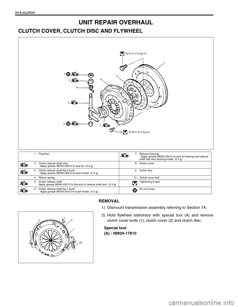
CLUTCH COVER, CLUTCH DISC AND FLYWHEEL
REMOVAL
1) Dismount transmission assembly referring to Section 7A.
2) Hold flywheel stationary with special tool (A) and remove
clutch cover bolts (1), clutch cover (2) and clutch disc.
Special tool
(A) : 09924-17810
1. Flywheel7. Release bearing
: Apply grease 99000-25010 to joint of bearing and release
shaft and also bearing inside. (0.3 g)
2. Clutch release shaft seal
: Apply grease 99000-25010 to seal lip. (0.3 g)8. Clutch cover
3. Clutch release shaft No.2 bush
: Apply grease 99000-25010 to bush inside. (0.3 g)9. Clutch disc
4. Return spring 10. Clutch cover bolt
5. Clutch release shaft
Apply grease 99000-25010 to the end of release shaft arm. (0.3 g)Tightening torque
6. Clutch release shaft No.1 bush
: Apply grease 99000-25010 to bush inside. (0.3 g)Do not reuse.
Page 191 of 447

CLUTCH 7C-9
3) Pull out input shaft bearing (1) by using special tool (B), and
wrench.
Special tool
(B) : 09921-26020
09930-30104
INSPECTION
Input Shaft Bearing
Check bearing (1) for smooth rotation and replace it if abnormality
is found.
Clutch Disc
Measure depth of rivet head depression, i.e. distance between
rivet head and facing surface. If depression is found to have
reached service limit at any of holes, replace disc assembly.
Rivet head depth
Standard : 1.65 – 2.25 mm (0.06 – 0.09 in.)
Service limit : 0.5 mm (0.02 in.)
Clutch Cover
1) Check diaphragm spring (1) for abnormal wear or damage.
2) Inspect pressure plate (2) for wear or heat spots.
3) If abnormality is found, replace it as assembly. Do not disas-
semble it into diaphragm and pressure plate.
Flywheel
Check surface contacting clutch disc for abnormal wear or heat
spots. Replace or repair as required.
Page 192 of 447
7C-10 CLUTCH
INSTALLATION
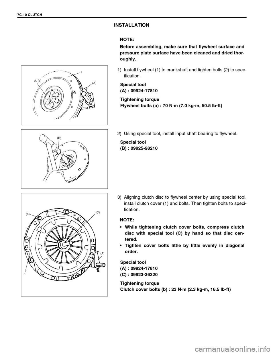
1) Install flywheel (1) to crankshaft and tighten bolts (2) to spec-
ification.
Special tool
(A) : 09924-17810
Tightening torque
Flywheel bolts (a) : 70 N·m (7.0 kg-m, 50.5 lb-ft)
2) Using special tool, install input shaft bearing to flywheel.
Special tool
(B) : 09925-98210
3) Aligning clutch disc to flywheel center by using special tool,
install clutch cover (1) and bolts. Then tighten bolts to speci-
fication.
Special tool
(A) : 09924-17810
(C) : 09923-36320
Tightening torque
Clutch cover bolts (b) : 23 N·m (2.3 kg-m, 16.5 lb-ft) NOTE:
Before assembling, make sure that flywheel surface and
pressure plate surface have been cleaned and dried thor-
oughly.
NOTE:
While tightening clutch cover bolts, compress clutch
disc with special tool (C) by hand so that disc cen-
tered.
Tighten cover bolts little by little evenly in diagonal
order.
Page 196 of 447
7C-14 CLUTCH
TIGHTENING TORQUE SPECIFICATION
REQUIRED SERVICE MATERIAL
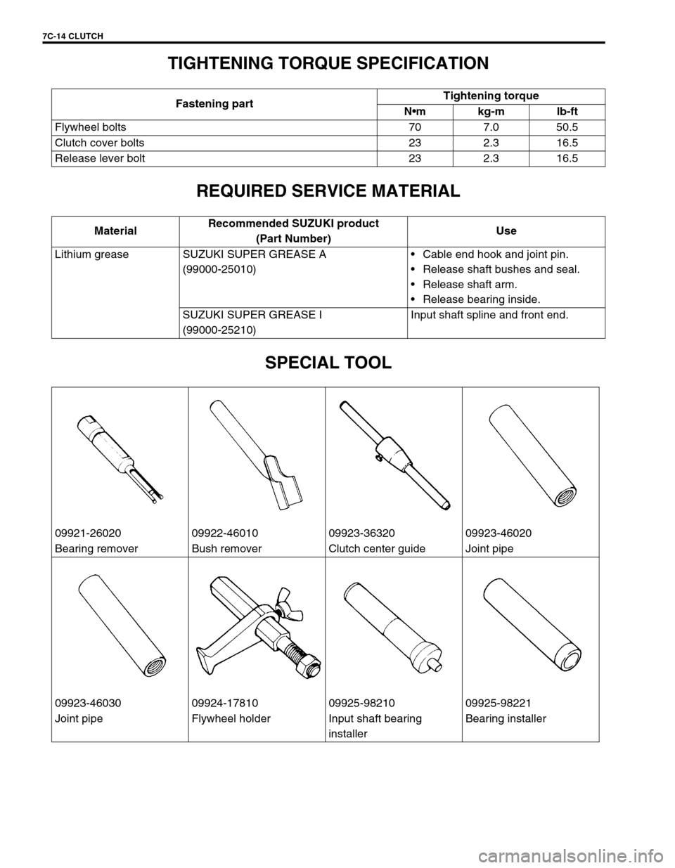
SPECIAL TOOL
Fastening partTightening torque
Nm kg-m lb-ft
Flywheel bolts 70 7.0 50.5
Clutch cover bolts 23 2.3 16.5
Release lever bolt 23 2.3 16.5
MaterialRecommended SUZUKI product
(Part Number)Use
Lithium grease SUZUKI SUPER GREASE A
(99000-25010)Cable end hook and joint pin.
Release shaft bushes and seal.
Release shaft arm.
Release bearing inside.
SUZUKI SUPER GREASE I
(99000-25210)Input shaft spline and front end.
09921-26020 09922-46010 09923-36320 09923-46020
Bearing remover Bush remover Clutch center guide Joint pipe
09923-46030 09924-17810 09925-98210 09925-98221
Joint pipe Flywheel holder Input shaft bearing
installerBearing installer
Page 203 of 447
TRANSFER 7D-5
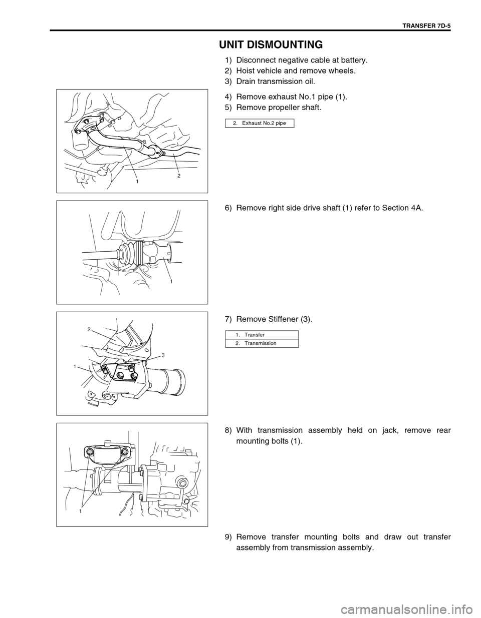
UNIT DISMOUNTING
1) Disconnect negative cable at battery.
2) Hoist vehicle and remove wheels.
3) Drain transmission oil.
4) Remove exhaust No.1 pipe (1).
5) Remove propeller shaft.
6) Remove right side drive shaft (1) refer to Section 4A.
7) Remove Stiffener (3).
8) With transmission assembly held on jack, remove rear
mounting bolts (1).
9) Remove transfer mounting bolts and draw out transfer
assembly from transmission assembly.
2. Exhaust No.2 pipe
12
1
1. Transfer
2. Transmission
1
Page 224 of 447
7F-2 REAR DIFFERENTIAL
GENERAL DESCRIPTION
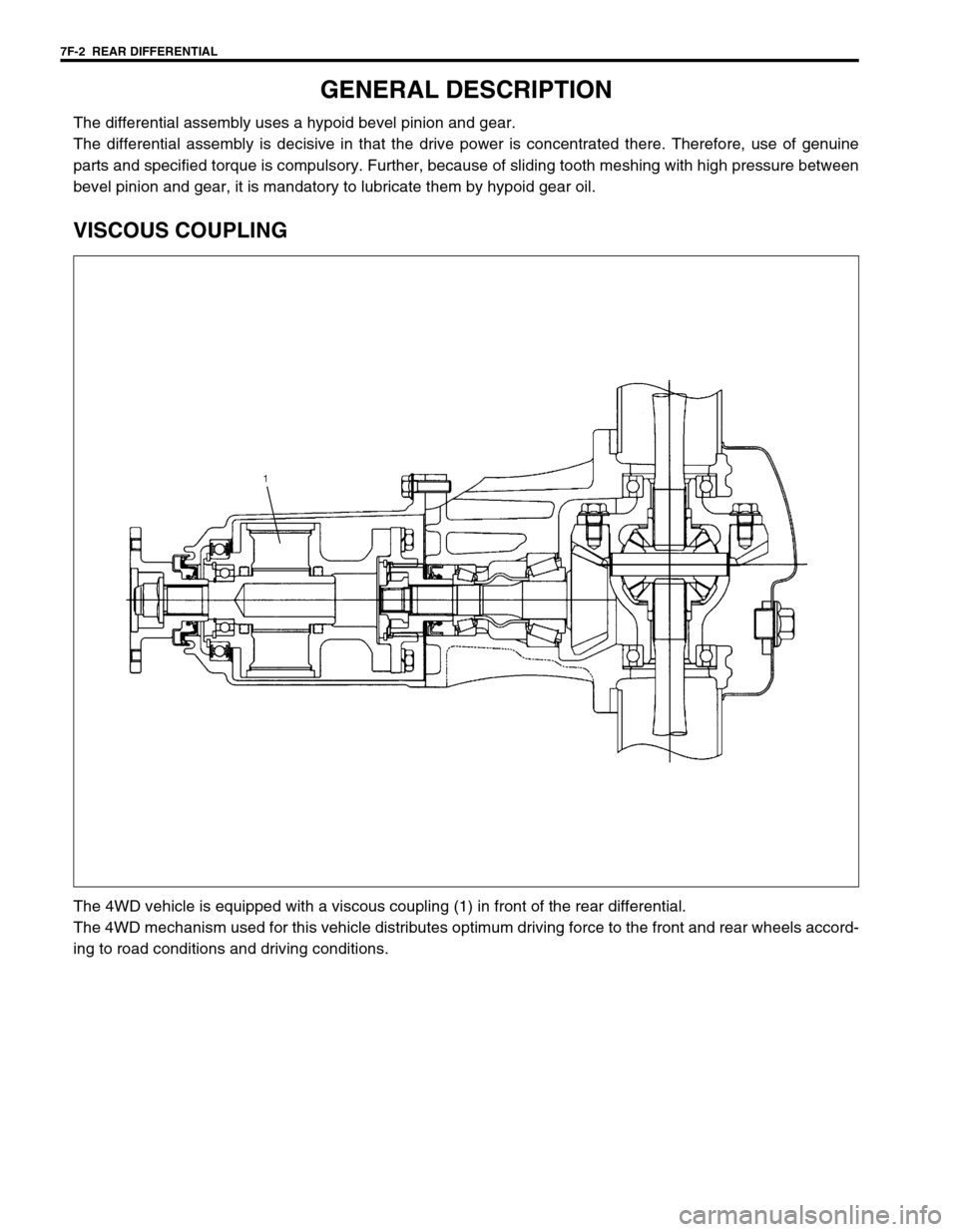
The differential assembly uses a hypoid bevel pinion and gear.
The differential assembly is decisive in that the drive power is concentrated there. Therefore, use of genuine
parts and specified torque is compulsory. Further, because of sliding tooth meshing with high pressure between
bevel pinion and gear, it is mandatory to lubricate them by hypoid gear oil.
VISCOUS COUPLING
The 4WD vehicle is equipped with a viscous coupling (1) in front of the rear differential.
The 4WD mechanism used for this vehicle distributes optimum driving force to the front and rear wheels accord-
ing to road conditions and driving conditions.
Page 228 of 447
7F-6 REAR DIFFERENTIAL
DIFFERENTIAL UNIT
DISMOUNTING
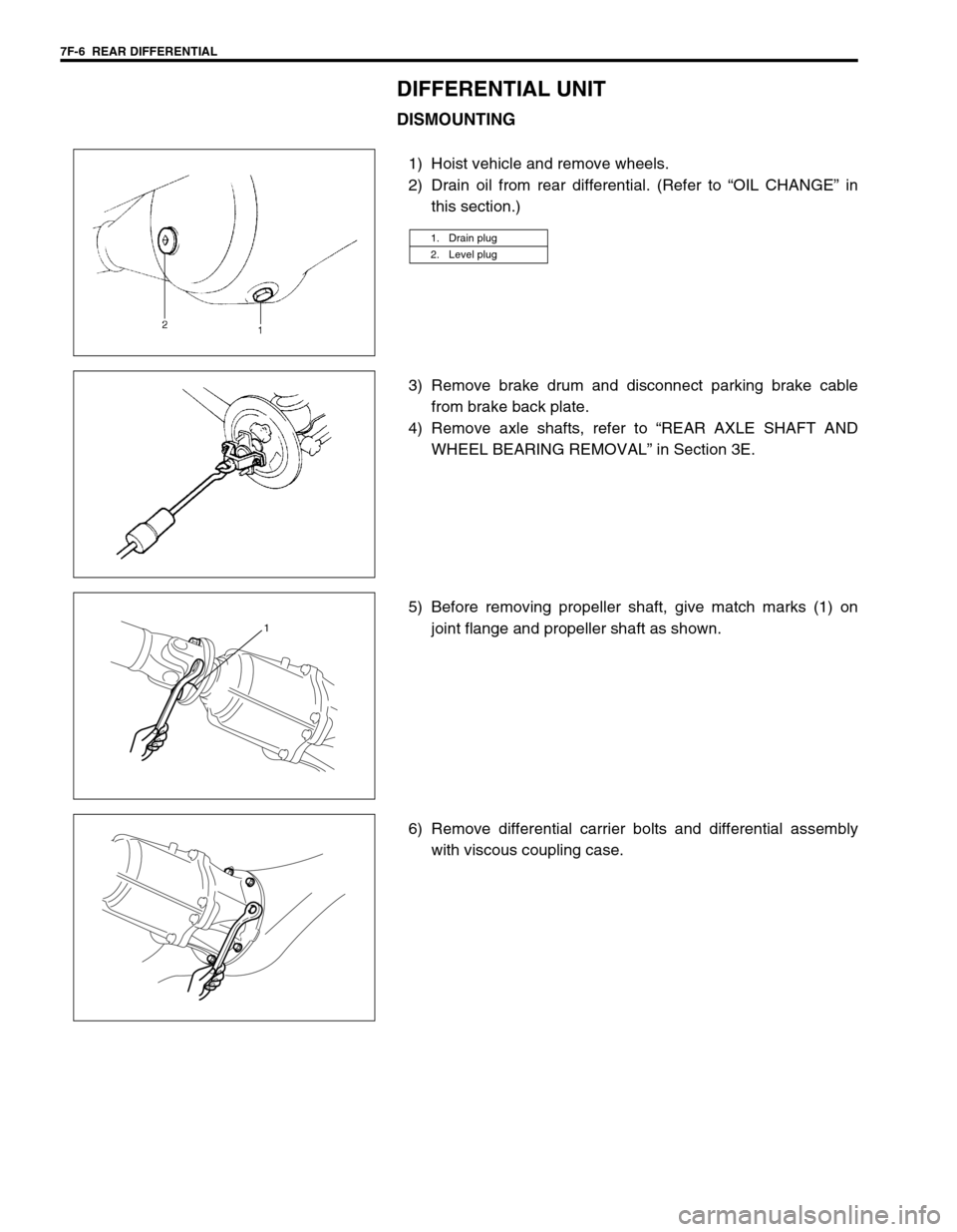
1) Hoist vehicle and remove wheels.
2) Drain oil from rear differential. (Refer to “OIL CHANGE” in
this section.)
3) Remove brake drum and disconnect parking brake cable
from brake back plate.
4) Remove axle shafts, refer to “REAR AXLE SHAFT AND
WHEEL BEARING REMOVAL” in Section 3E.
5) Before removing propeller shaft, give match marks (1) on
joint flange and propeller shaft as shown.
6) Remove differential carrier bolts and differential assembly
with viscous coupling case.
1. Drain plug
2. Level plug
1
Page 229 of 447
REAR DIFFERENTIAL 7F-7
REMOUNTING
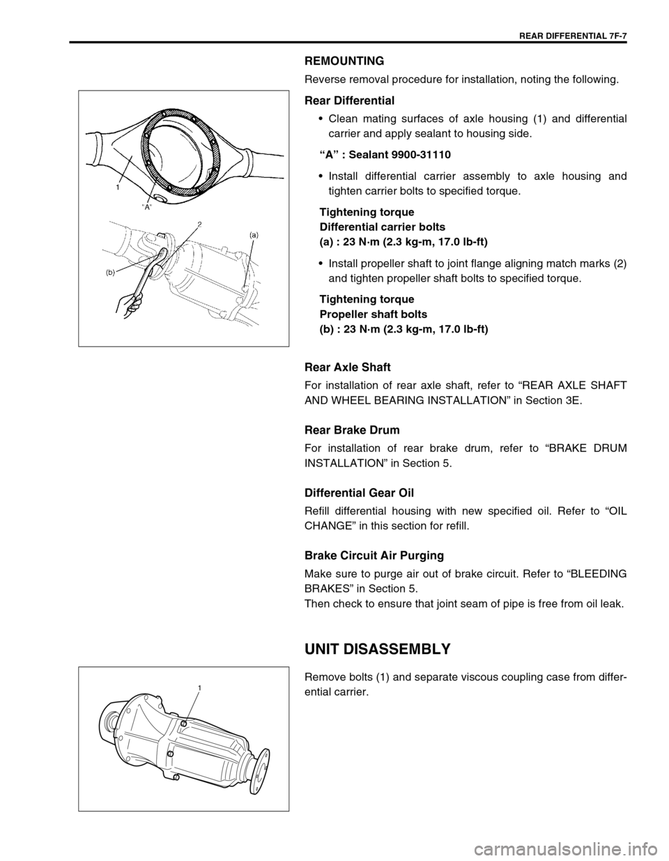
Reverse removal procedure for installation, noting the following.
Rear Differential
Clean mating surfaces of axle housing (1) and differential
carrier and apply sealant to housing side.
“A” : Sealant 9900-31110
Install differential carrier assembly to axle housing and
tighten carrier bolts to specified torque.
Tightening torque
Differential carrier bolts
(a) : 23 N·m (2.3 kg-m, 17.0 lb-ft)
Install propeller shaft to joint flange aligning match marks (2)
and tighten propeller shaft bolts to specified torque.
Tightening torque
Propeller shaft bolts
(b) : 23 N·m (2.3 kg-m, 17.0 lb-ft)
Rear Axle Shaft
For installation of rear axle shaft, refer to “REAR AXLE SHAFT
AND WHEEL BEARING INSTALLATION” in Section 3E.
Rear Brake Drum
For installation of rear brake drum, refer to “BRAKE DRUM
INSTALLATION” in Section 5.
Differential Gear Oil
Refill differential housing with new specified oil. Refer to “OIL
CHANGE” in this section for refill.
Brake Circuit Air Purging
Make sure to purge air out of brake circuit. Refer to “BLEEDING
BRAKES” in Section 5.
Then check to ensure that joint seam of pipe is free from oil leak.
UNIT DISASSEMBLY
Remove bolts (1) and separate viscous coupling case from differ-
ential carrier.1
Page 354 of 447
9-50 BODY SERVICE
PAINT AND COATINGS
ANTI-CORROSION TREATMENT
As rust proof treatment, steel sheets are given corrosion resistance on the interior and/or exterior.
These corrosion resistance steel sheet materials are called one of two-side galvanized steel sheets.
It is for the sake of rust protection that these materials are selected and given a variety of treatments as
described blow.
Steel sheets are treated with cathodic electroprimer which is excellent in corrosion resistance.
Rust proof wax coatings are applied to door and side sill insides where moisture is liable to stay.
Vinyl coating is applied to body underside and wheel housing inside.
Sealer is applied to door hem, engine compartment steel sheet-to-steel sheet joint, and the like portions to
prevent water penetration and resulting in rust occurrence.
In panel replacement or collision damage repair, leaving the relevant area untreated as it is in any operation
which does disturb the above-mentioned rust proof treatment will cause corrosion to that area. Therefore, it is
the essential function of any repair operation to correctly recoat the related surfaces of the relevant area.
All the metal panels are coated with metal conditioners and primer coating during vehicle production. Following
the repair and/or replacement parts installation, every accessible bare metal surface should be cleaned and
coated with rust proof primer. Perform this operation prior to the application of sealer and rust proof wax coating.
Sealer is applied to the specific joints of a vehicle during production. The sealer is intended to prevent dust from
entering the vehicle and serves also as an anticorrosion barrier. The sealer is applied to the door and hood hem
areas and between panels. Correct and reseal the originally sealed joints if damaged. Reseal the attaching
joints of a new replacement panel and reseal the hem area of a replacement door or hood.
Use a quality sealer to seal the flanged joints, overlap joints and seams. The sealer must have flexible character-
istics and paint ability after it’s applied to repair areas.
For the sealer to fill open joints, use caulking material. Select a sealer in conformance with the place and pur-
pose of a specific use. Observe the manufacturer’s label-stand instructions when using the sealer.
In many cases, repaired places require color painting. When this is required, follow the ordinary techniques
specified for the finish preparation, color painting and undercoating build-up.
Rust proof wax, a penetrative compound, is applied to the metal-to-metal surfaces (door and side sill insides)
where it is difficult to use ordinary undercoating material for coating. Therefore, when selecting the rust proof
wax, it may be the penetrative type.
During the undercoating (vinyl coating) application, care should be taken that sealer is not applied to the engine-
related parts and shock absorber mounting or rotating parts. Following the under coating, make sure that body
drain holes are kept open.
The sequence of the application steps of the anti-corrosion materials are as follows:
1) Clean and prepare the metal surface.
2) Apply primer.
3) Apply sealer (all joints sealed originally).
4) Apply color in areas where color is required such as hem flanges, exposed joints and under body compo-
nents.
5) Apply anticorrosion compound (penetrative wax).
6) Apply undercoating (rust proof material).WARNING:
Standard shop practices, particularly eye protection, should be followed during the performance of the
below-itemized operations to avoid personal injury.
Page 381 of 447

AIR BAG SYSTEM 10B-7
The adapter will also give an idea of whether contact tension is
sufficient, helping to find an open or intermittent open due to poor
terminal contact.
Special tool
(B) : 09932-75010 (Air Bag Driver/Passenger Load Tool)
This tool is used only when called for in this section. It is used as
a diagnostic aid and safety device to prevent inadvertent air bag
(inflator) module deployment.
The load tool has three connectors attached to its case which are
electrically functional and serve as resistive load substitutions.
No more than two connectors are used at any time.
One of connectors (“STEERING WHEEL”) is used to substitute
the load of followings.
driver air bag (inflator) module when it is connected at the
top of the column to the contact coil assembly.
passenger air bag (inflator) module when it is connected to
the air bag harness connector for passenger air bag (inflator)
module.
Another connector (“BASE OF COLUMN”) is used to substitute
the load of the driver air bag (inflator) module and the contact coil
assembly when it is connected at the base of the column to the air
bag wire harness.
The third connector (“PASSENGER INFLATOR”) is not used.
By substituting the resistance of the load tool when called for, a
determination can be made as to whether an inflator circuit com-
ponent is causing system malfunction and which component is
causing the malfunction.
The load tool should be used only when specifically called for in
the diagnostic procedures.
1. Connector for contact coil and driver air bag (inflator) module
(Located near the base of the steering column)
2. Connector for driver, passenger air bag (inflator) module and driver and
passenger seat belt pretensioners
3. Not used