stop start SUZUKI SWIFT 2000 1.G Transmission Service Workshop Manual
[x] Cancel search | Manufacturer: SUZUKI, Model Year: 2000, Model line: SWIFT, Model: SUZUKI SWIFT 2000 1.GPages: 447, PDF Size: 10.54 MB
Page 61 of 447
AUTOMATIC TRANSMISSION (4 A/T) 7B-19
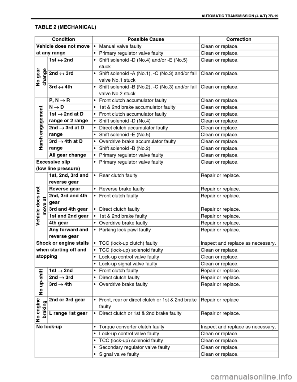
TABLE 2 (MECHANICAL)
Condition Possible Cause Correction
Vehicle does not move
at any rangeManual valve faulty Clean or replace.
Primary regulator valve faulty Clean or replace.
No gear
change
1st
↔
↔↔ ↔ 2nd
Shift solenoid -D (No.4) and/or -E (No.5)
stuck Clean or replace.
2nd
↔
↔↔ ↔ 3rd
Shift solenoid -A (No.1), -C (No.3) and/or fail
valve No.1 stuckClean or replace.
3rd
↔
↔↔ ↔ 4th
Shift solenoid -B (No.2), -C (No.3) and/or fail
valve No.2 stuckClean or replace.
Harsh engagement
P, N
→
→→ → R
Front clutch accumulator faulty Clean or replace.
N
→
→→ → D
1st & 2nd brake accumulator faulty Clean or replace.
1st
→
→→ → 2nd at D
range or 2 rangeFront clutch accumulator faulty Clean or replace.
Shift solenoid -D (No.4) Clean or replace.
2nd
→
→→ → 3rd at D
rangeDirect clutch accumulator faulty Clean or replace.
Shift solenoid -E (No.5) Clean or replace.
3rd
→
→→ → 4th at D
rangeOverdrive brake accumulator faulty Clean or replace.
Shift solenoid -B (No.2) Clean or replace.
All gear change
Primary regulator valve faulty Clean or replace.
Excessive slip
(low line pressure)Primary regulator valve faulty Clean or replace.
Vehicle does not
move at
1st, 2nd, 3rd and
reverse gearRear clutch faulty Repair or replace.
Reverse gear
Reverse brake faulty Repair or replace.
2nd, 3rd and 4th
gearFront clutch faulty Repair or replace.
3rd and 4th gear
Direct clutch faulty Repair or replace.
1st and 2nd gear
1st & 2nd brake faulty Repair or replace.
4th gear
Overdrive brake faulty Repair or replace.
Any forward and
reverse gearParking lock pawl faulty Repair or replace.
Shock or engine stalls
when starting off and
stoppingTCC (lock-up clutch) faulty Inspect and replace as necessary.
TCC (lock-up) solenoid faulty Clean or replace.
Lock-up control valve faulty Clean or replace.
Lock-up signal valve faulty Clean or replace.
No up-shift
1st
→
→→ → 2nd
Front clutch faulty Repair or replace.
2nd
→
→→ → 3rd
Direct clutch faulty Repair or replace.
3rd
→
→→ → 4th
Overdrive brake faulty Repair or replace.
No engine
braking
2nd or 3rd gear
Front, rear or direct clutch or 1st & 2nd brake
faultyRepair or replace
L range 1st gear
Direct clutch or 1st & 2nd brake faulty Repair or replace.
No lock-up
Torque converter clutch faulty Inspect and replace as necessary.
Lock-up control valve faulty Clean or replace.
TCC (lock-up) solenoid faulty Clean or replace.
Secondary regulator valve faulty Clean or replace.
Signal valve faulty Clean or replace.
Page 63 of 447
AUTOMATIC TRANSMISSION (4 A/T) 7B-21
TIME LAG TEST
This test is to check conditions of clutch, reverse brake and fluid
pressure. “Time lag” means time elapsed since select lever is
shifted with engine idling till shock is felt.
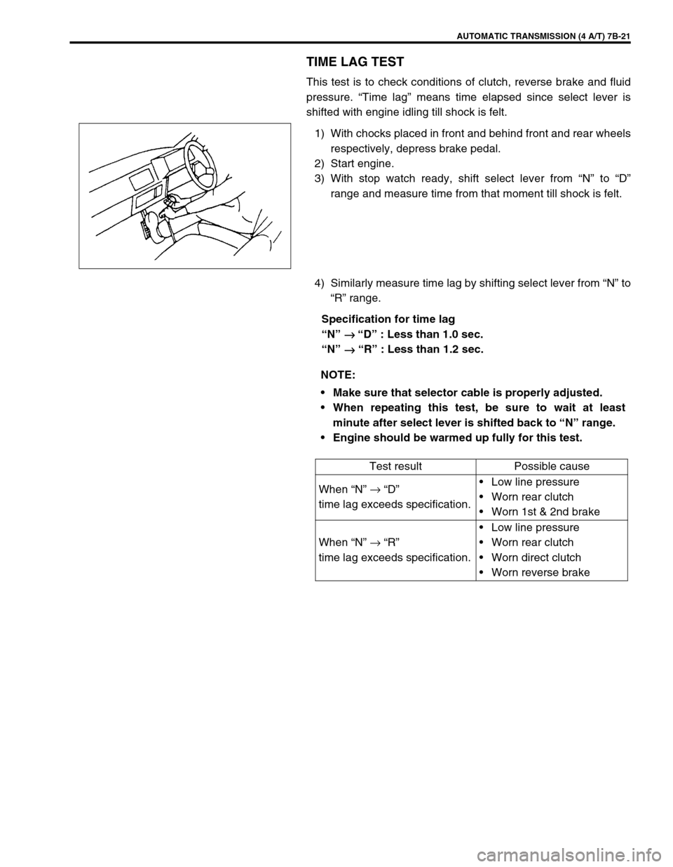
1) With chocks placed in front and behind front and rear wheels
respectively, depress brake pedal.
2) Start engine.
3) With stop watch ready, shift select lever from “N” to “D”
range and measure time from that moment till shock is felt.
4) Similarly measure time lag by shifting select lever from “N” to
“R” range.
Specification for time lag
“N”
→
→ → → “D” : Less than 1.0 sec.
“N”
→
→→ → “R” : Less than 1.2 sec.
NOTE:
Make sure that selector cable is properly adjusted.
When repeating this test, be sure to wait at least
minute after select lever is shifted back to “N” range.
Engine should be warmed up fully for this test.
Test result Possible cause
When “N” →
“D”
time lag exceeds specification.Low line pressure
Worn rear clutch
Worn 1st & 2nd brake
When “N” →
“R”
time lag exceeds specification.Low line pressure
Worn rear clutch
Worn direct clutch
Worn reverse brake
Page 97 of 447
AUTOMATIC TRANSMISSION (4 A/T) 7B-55
ON-VEHICLE SERVICE
MAINTENANCE SERVICE
FLUID LEVEL AT NORMAL OPERATING TEMPERA-
TURE
INSPECTION
1) Stop vehicle and place it level.
2) Apply parking brake and place chocks against wheels.
3) With selector at P position, start engine.
4) Warm up engine till fluid temperature reaches normal oper-
ating temperature (70 – 80°C/158 – 176°F). As a guide to
check fluid temperature, warm up engine to normal operat-
ing temperature.
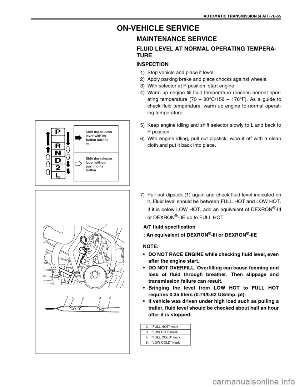
5) Keep engine idling and shift selector slowly to L and back to
P position.
6) With engine idling, pull out dipstick, wipe it off with a clean
cloth and put it back into place.
7) Pull out dipstick (1) again and check fluid level indicated on
it. Fluid level should be between FULL HOT and LOW HOT.
If it is below LOW HOT, add an equivalent of DEXRON
®-III
or DEXRON
®-IIE up to FULL HOT.
A/T fluid specification
: An equivalent of DEXRON
®-III or DEXRON®-IIE
NOTE:
DO NOT RACE ENGINE while checking fluid level, even
after the engine start.
DO NOT OVERFILL. Overfilling can cause foaming and
loss of fluid through breather. Then slippage and
transmission failure can result.
Bringing the level from LOW HOT to FULL HOT
requires 0.35 liters (0.74/0.62 US/Imp. pt).
If vehicle was driven under high load such as pulling a
trailer, fluid level should be checked about half an hour
after it is stopped.
2.“FULL HOT” mark
3.“LOW HOT” mark
4.“FULL COLD” mark
5.“LOW COLD” mark
1
Page 280 of 447
8G-2 IMMOBILIZER CONTROL SYSTEM
PROCEDURE AFTER IMMOBILIZER CONTROL
MODULE REPLACEMENT ........................... 8G-24
PROCEDURE AFTER ECM
REPLACEMENT............................................ 8G-25SPECIAL TOOL ............................................ 8G-25
GENERAL DESCRIPTION
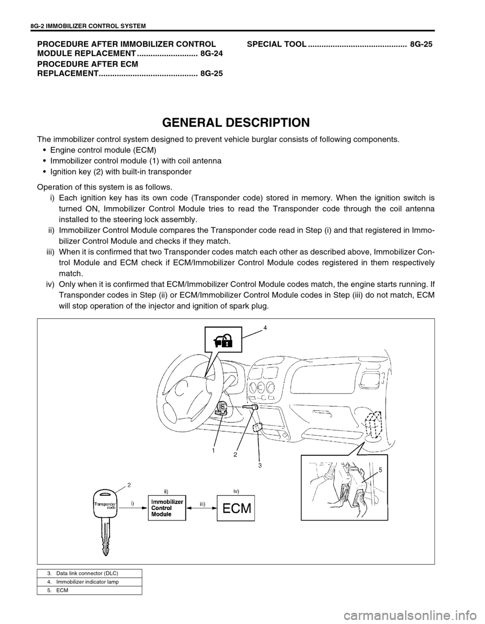
The immobilizer control system designed to prevent vehicle burglar consists of following components.
Engine control module (ECM)
Immobilizer control module (1) with coil antenna
Ignition key (2) with built-in transponder
Operation of this system is as follows.
i) Each ignition key has its own code (Transponder code) stored in memory. When the ignition switch is
turned ON, Immobilizer Control Module tries to read the Transponder code through the coil antenna
installed to the steering lock assembly.
ii) Immobilizer Control Module compares the Transponder code read in Step (i) and that registered in Immo-
bilizer Control Module and checks if they match.
iii) When it is confirmed that two Transponder codes match each other as described above, Immobilizer Con-
trol Module and ECM check if ECM/Immobilizer Control Module codes registered in them respectively
match.
iv) Only when it is confirmed that ECM/Immobilizer Control Module codes match, the engine starts running. If
Transponder codes in Step (ii) or ECM/Immobilizer Control Module codes in Step (iii) do not match, ECM
will stop operation of the injector and ignition of spark plug.
3. Data link connector (DLC)
4. Immobilizer indicator lamp
5. ECM
Page 316 of 447
9-12 BODY SERVICE
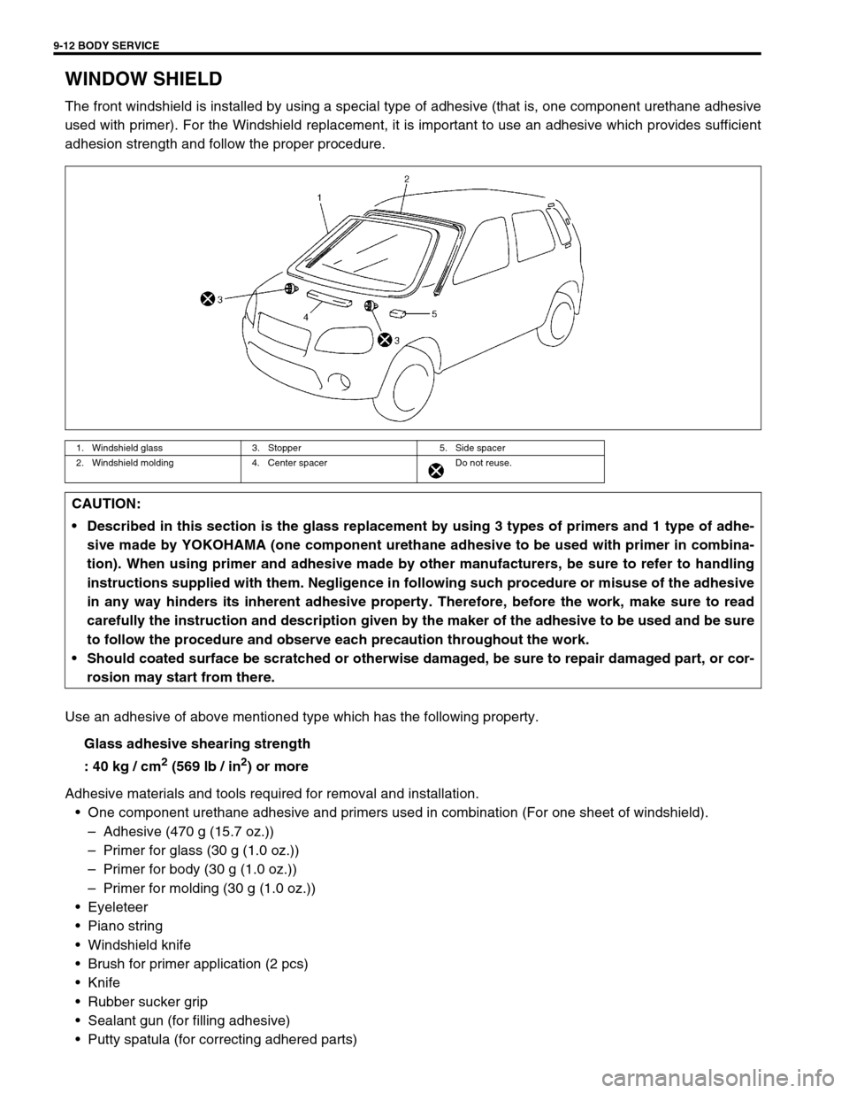
WINDOW SHIELD
The front windshield is installed by using a special type of adhesive (that is, one component urethane adhesive
used with primer). For the Windshield replacement, it is important to use an adhesive which provides sufficient
adhesion strength and follow the proper procedure.
Use an adhesive of above mentioned type which has the following property.
Glass adhesive shearing strength
: 40 kg / cm
2 (569 lb / in2) or more
Adhesive materials and tools required for removal and installation.
One component urethane adhesive and primers used in combination (For one sheet of windshield).
–Adhesive (470 g (15.7 oz.))
–Primer for glass (30 g (1.0 oz.))
–Primer for body (30 g (1.0 oz.))
–Primer for molding (30 g (1.0 oz.))
Eyeleteer
Piano string
Windshield knife
Brush for primer application (2 pcs)
Knife
Rubber sucker grip
Sealant gun (for filling adhesive)
Putty spatula (for correcting adhered parts)
1. Windshield glass 3. Stopper 5. Side spacer
2. Windshield molding 4. Center spacer Do not reuse.
CAUTION:
Described in this section is the glass replacement by using 3 types of primers and 1 type of adhe-
sive made by YOKOHAMA (one component urethane adhesive to be used with primer in combina-
tion). When using primer and adhesive made by other manufacturers, be sure to refer to handling
instructions supplied with them. Negligence in following such procedure or misuse of the adhesive
in any way hinders its inherent adhesive property. Therefore, before the work, make sure to read
carefully the instruction and description given by the maker of the adhesive to be used and be sure
to follow the procedure and observe each precaution throughout the work.
Should coated surface be scratched or otherwise damaged, be sure to repair damaged part, or cor-
rosion may start from there.
Page 432 of 447
10B-58 AIR BAG SYSTEM
PASSENGER AIR BAG (INFLATOR) MODULE (IF EQUIPPED)
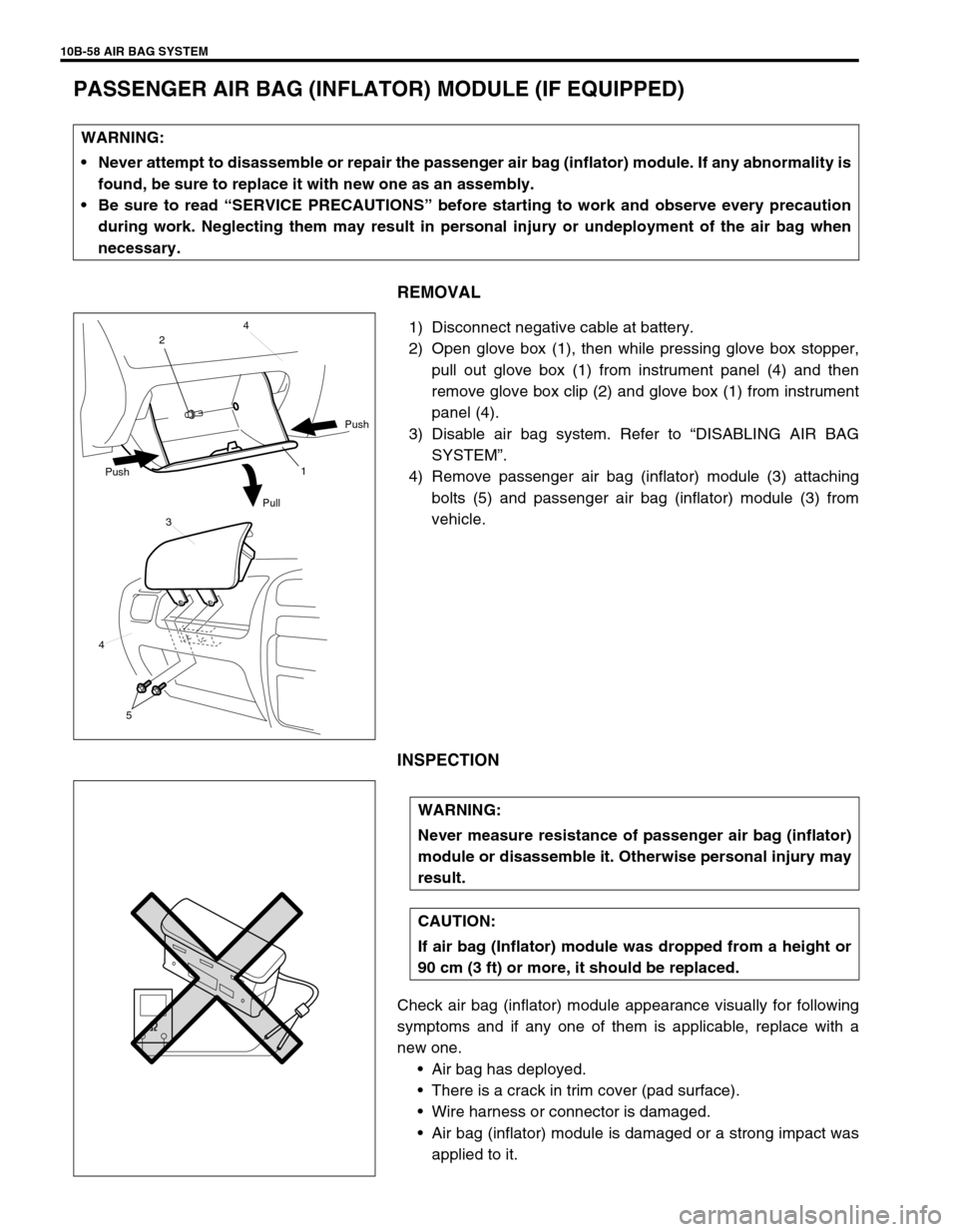
REMOVAL
1) Disconnect negative cable at battery.
2) Open glove box (1), then while pressing glove box stopper,
pull out glove box (1) from instrument panel (4) and then
remove glove box clip (2) and glove box (1) from instrument
panel (4).
3) Disable air bag system. Refer to “DISABLING AIR BAG
SYSTEM”.
4) Remove passenger air bag (inflator) module (3) attaching
bolts (5) and passenger air bag (inflator) module (3) from
vehicle.
INSPECTION
Check air bag (inflator) module appearance visually for following
symptoms and if any one of them is applicable, replace with a
new one.
Air bag has deployed.
There is a crack in trim cover (pad surface).
Wire harness or connector is damaged.
Air bag (inflator) module is damaged or a strong impact was
applied to it. WARNING:
Never attempt to disassemble or repair the passenger air bag (inflator) module. If any abnormality is
found, be sure to replace it with new one as an assembly.
Be sure to read “SERVICE PRECAUTIONS” before starting to work and observe every precaution
during work. Neglecting them may result in personal injury or undeployment of the air bag when
necessary.
1 24
Push
Pull Push
3
4
5
WARNING:
Never measure resistance of passenger air bag (inflator)
module or disassemble it. Otherwise personal injury may
result.
CAUTION:
If air bag (Inflator) module was dropped from a height or
90 cm (3 ft) or more, it should be replaced.