Electri SUZUKI SWIFT 2000 1.G Transmission Service Owner's Manual
[x] Cancel search | Manufacturer: SUZUKI, Model Year: 2000, Model line: SWIFT, Model: SUZUKI SWIFT 2000 1.GPages: 447, PDF Size: 10.54 MB
Page 254 of 447
8-10 BODY ELECTRICAL SYSTEM
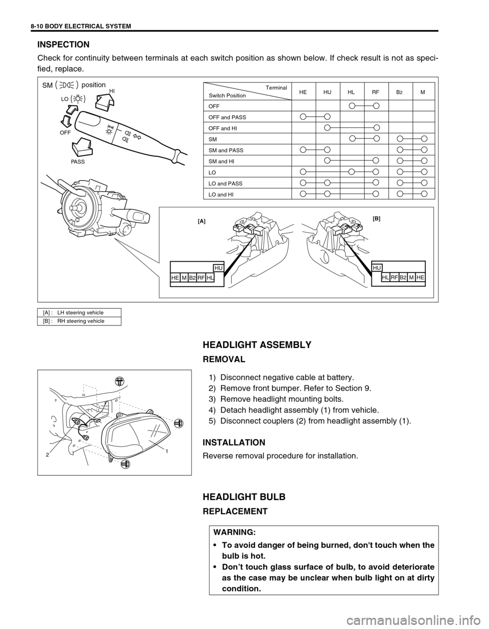
INSPECTION
Check for continuity between terminals at each switch position as shown below. If check result is not as speci-
fied, replace.
HEADLIGHT ASSEMBLY
REMOVAL
1) Disconnect negative cable at battery.
2) Remove front bumper. Refer to Section 9.
3) Remove headlight mounting bolts.
4) Detach headlight assembly (1) from vehicle.
5) Disconnect couplers (2) from headlight assembly (1).
INSTALLATION
Reverse removal procedure for installation.
HEADLIGHT BULB
REPLACEMENT
[A] : LH steering vehicle
[B] : RH steering vehicle
HISMposition
PASS OFFLO
[B]
HU
HL RF B2 M HE [A]
HUHL
RF B2 M HE
Switch PositionTerminal
OFF
OFF and PASS
OFF and HI
SM
SM and PASS
SM and HI
LO
LO and PASS
LO and HIHE HU HL RF B2M
21
WARNING:
To avoid danger of being burned, don't touch when the
bulb is hot.
Don’t touch glass surface of bulb, to avoid deteriorate
as the case may be unclear when bulb light on at dirty
condition.
Page 255 of 447
BODY ELECTRICAL SYSTEM 8-11
1) Disconnect negative cable at battery.
2) Disconnect coupler from bulb.
3) Remove socket cover (1).
4) Replace bulb (2) and assemble all removed parts.
HEADLIGHT AIMING ADJUSTMENT WITH SCREEN
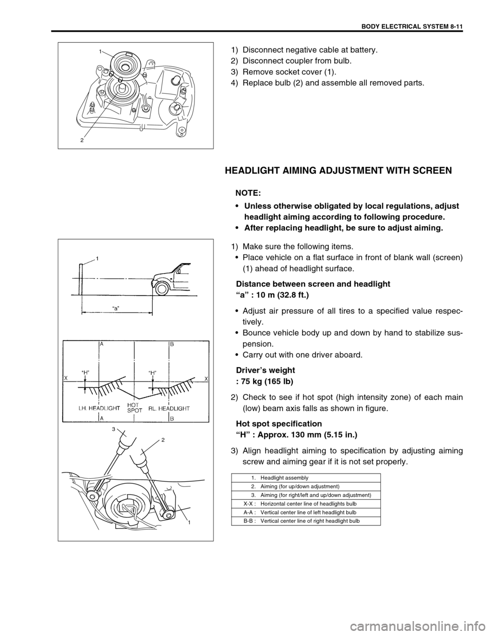
1) Make sure the following items.
Place vehicle on a flat surface in front of blank wall (screen)
(1) ahead of headlight surface.
Distance between screen and headlight
“a” : 10 m (32.8 ft.)
Adjust air pressure of all tires to a specified value respec-
tively.
Bounce vehicle body up and down by hand to stabilize sus-
pension.
Carry out with one driver aboard.
Driver’s weight
: 75 kg (165 lb)
2) Check to see if hot spot (high intensity zone) of each main
(low) beam axis falls as shown in figure.
Hot spot specification
“H” : Approx. 130 mm (5.15 in.)
3) Align headlight aiming to specification by adjusting aiming
screw and aiming gear if it is not set properly.
21
NOTE:
Unless otherwise obligated by local regulations, adjust
headlight aiming according to following procedure.
After replacing headlight, be sure to adjust aiming.
1. Headlight assembly
2. Aiming (for up/down adjustment)
3. Aiming (for right/left and up/down adjustment)
X-X : Horizontal center line of headlights bulb
A-A : Vertical center line of left headlight bulb
B-B : Vertical center line of right headlight bulb
1 2 3
Page 256 of 447
8-12 BODY ELECTRICAL SYSTEM
HEADLIGHT LEVELING SWITCH (IF EQUIPPED)
INSPECTION
Check for resistance between terminals at each switch position
as shown below. If check result is not as specified, replace.
Headlight leveling switch resistance
TURN SIGNAL AND HAZARD WARNING LIGHTS
TURN SIGNAL LIGHT SWITCH
REMOVAL AND INSTALLATION
Refer to “CONTACT COIL AND COMBINATION SWITCH ASSEMBLY” in Section 3C.
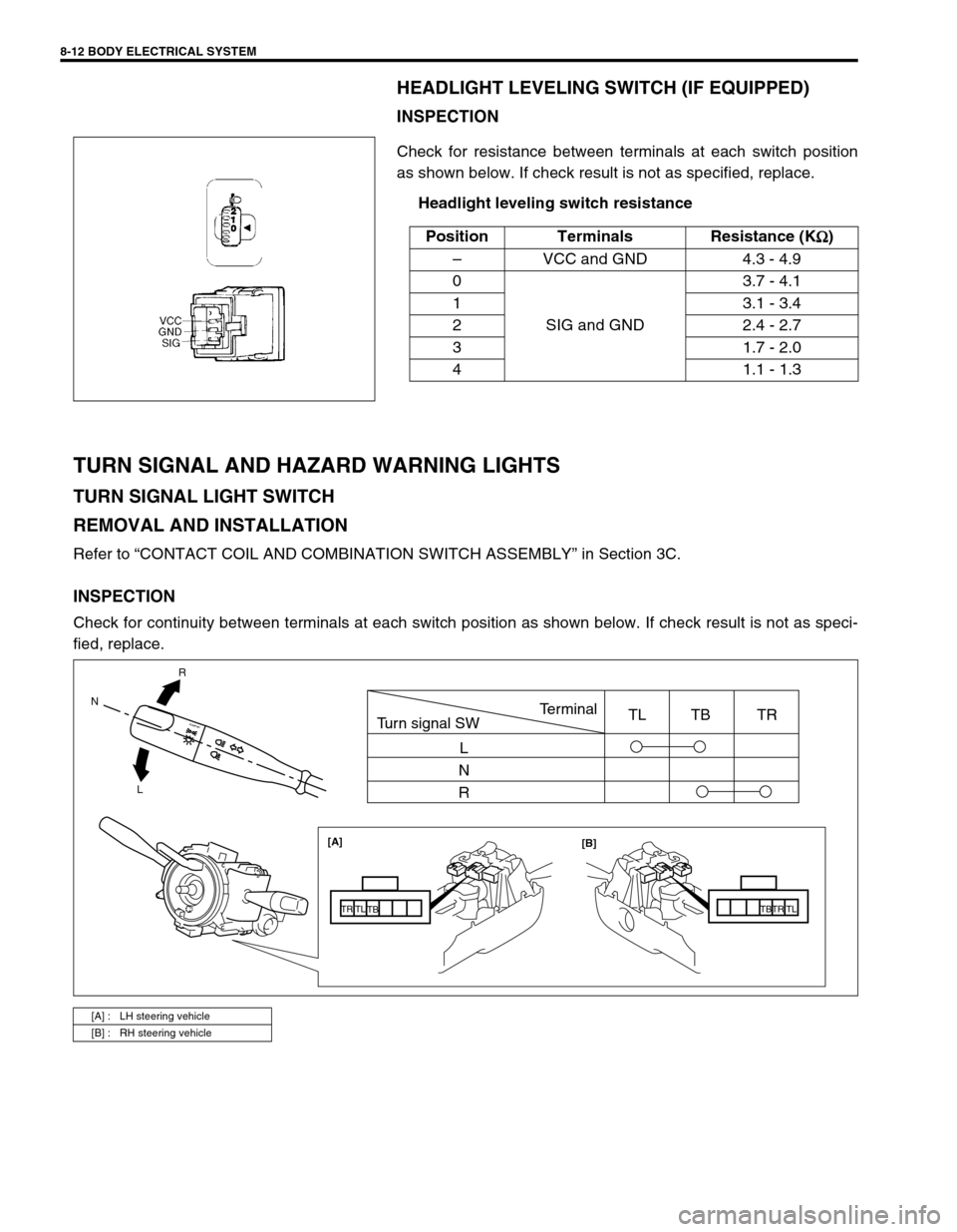
INSPECTION
Check for continuity between terminals at each switch position as shown below. If check result is not as speci-
fied, replace.Position Terminals Resistance (K
Ω
ΩΩ Ω)
–VCC and GND 4.3 - 4.9
0
SIG and GND3.7 - 4.1
1 3.1 - 3.4
2 2.4 - 2.7
3 1.7 - 2.0
4 1.1 - 1.3
[A] : LH steering vehicle
[B] : RH steering vehicle
R
L N
[A]
[B]
TB
TBTR TR
TL TL
Turn signal SWTerminal
L
N
RTL TB TR
Page 257 of 447
BODY ELECTRICAL SYSTEM 8-13
TURN SIGNAL AND HAZARD RELAY
The turn signal and hazard relay (1) is located near the fuse box
(2).
INSPECTION
Connect turn signal and hazard relay (1), battery (3) and two test
bulbs (12 V, 27 W) (2) as shown.
Unless a continued flash on and off is visible, replace.
Reference flashing cycle
: 60 - 120 cycle/minute
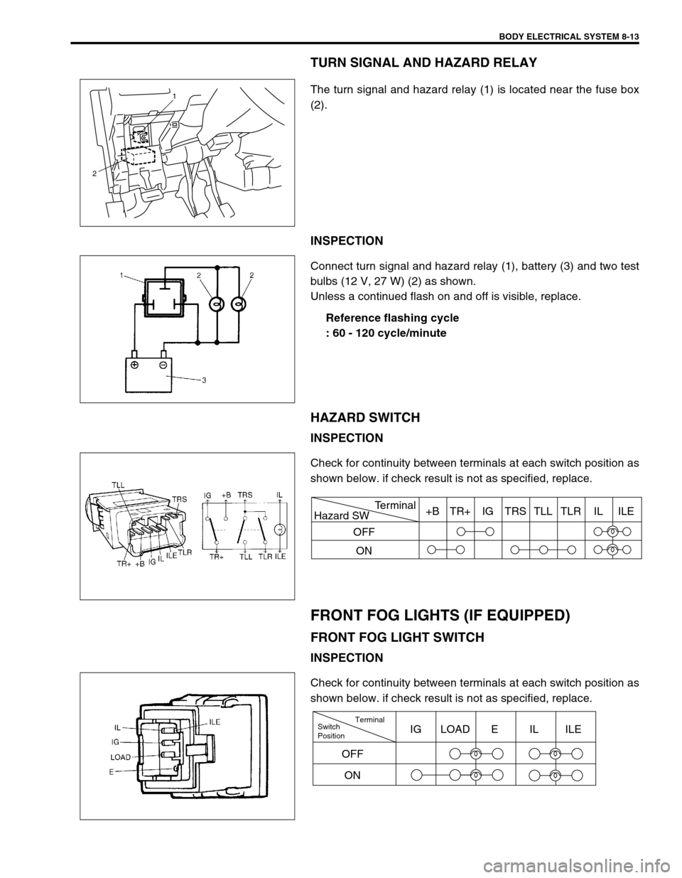
HAZARD SWITCH
INSPECTION
Check for continuity between terminals at each switch position as
shown below. if check result is not as specified, replace.
FRONT FOG LIGHTS (IF EQUIPPED)
FRONT FOG LIGHT SWITCH
INSPECTION
Check for continuity between terminals at each switch position as
shown below. if check result is not as specified, replace.
1
2
Hazard SWTerminal
OFF
ON+B TR+ IG TRS TLL TLR IL ILE
Switch
PositionTerminal
ONIG LOAD E IL ILE
OFF
Page 258 of 447
8-14 BODY ELECTRICAL SYSTEM
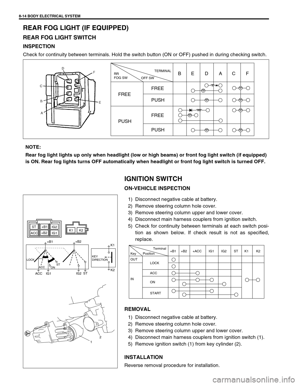
REAR FOG LIGHT (IF EQUIPPED)
REAR FOG LIGHT SWITCH
INSPECTION
Check for continuity between terminals. Hold the switch button (ON or OFF) pushed in during checking switch.
IGNITION SWITCH
ON-VEHICLE INSPECTION
1) Disconnect negative cable at battery.
2) Remove steering column hole cover.
3) Remove steering column upper and lower cover.
4) Disconnect main harness couplers from ignition switch.
5) Check for continuity between terminals at each switch posi-
tion as shown below. If check result is not as specified,
replace.
REMOVAL
1) Disconnect negative cable at battery.
2) Remove steering column hole cover.
3) Remove steering column upper and lower cover.
4) Disconnect main harness couplers from ignition switch (1).
5) Remove ignition switch (1) from key cylinder (2).
INSTALLATION
Reverse removal procedure for installation.
RR
FOG SW
OFF SWTERMINAL
FREEFREE
PUSH
FREE
PUSH PUSHBE D AC F
NOTE:
Rear fog light lights up only when headlight (low or high beams) or front fog light switch (if equipped)
is ON. Rear fog lights turns OFF automatically when headlight or front fog light switch is turned OFF.
ST+B1
+B2
ACCIG2
IG1K1K2
+B1+B2
ACC IG1IG2STK1
K2
LOCK
ACC
ONSTKEY
DIRECTION
12
Position Key
OUT
LOCK
ACC
ON
START IN+B1 +B2 +ACC IG1 IG2 ST K1 K2 Terminal
Page 259 of 447
BODY ELECTRICAL SYSTEM 8-15
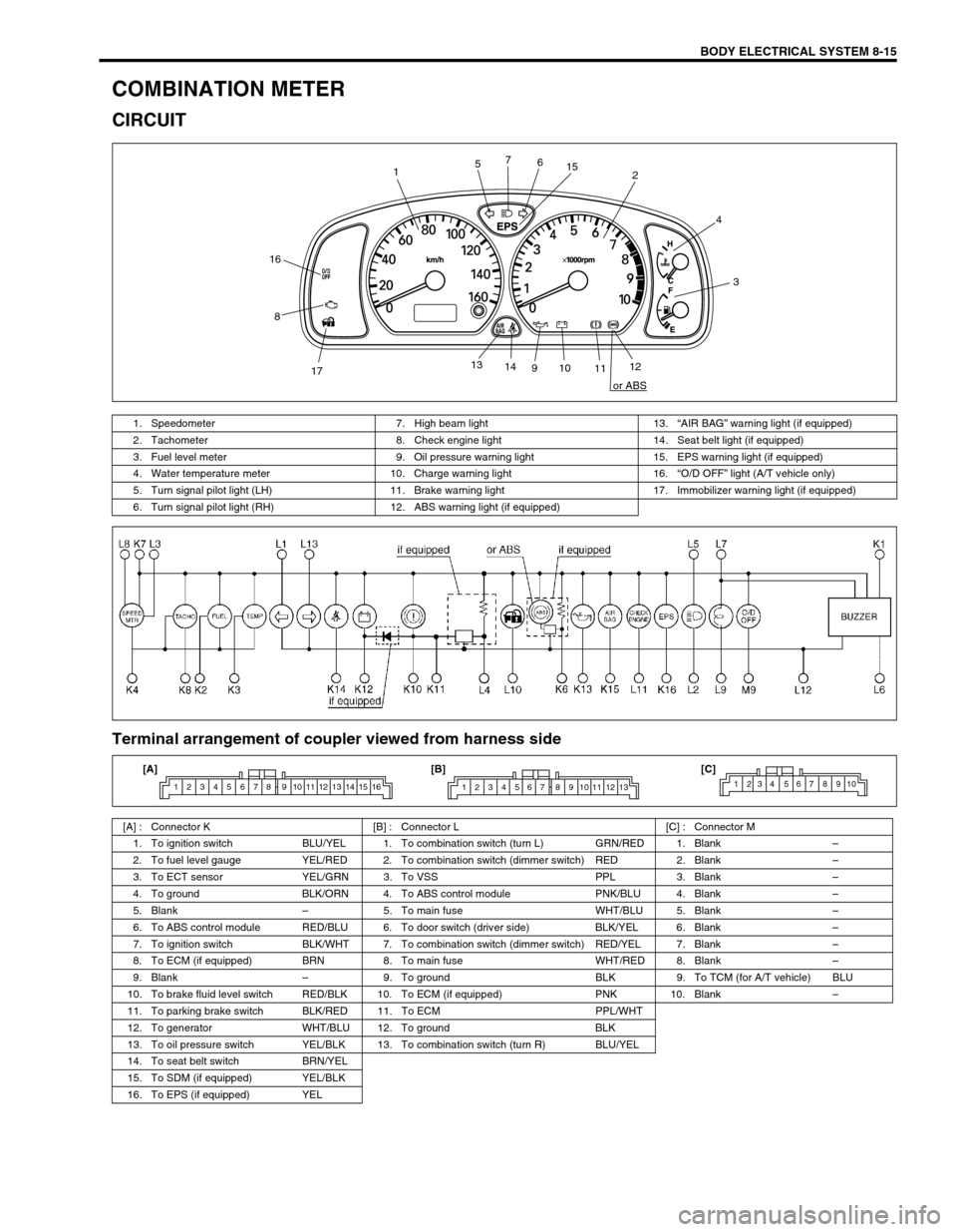
COMBINATION METER
CIRCUIT
Terminal arrangement of coupler viewed from harness side
12
3 4
56 7
8
910
1112 13
14
1715
16
or ABS
1. Speedometer 7. High beam light 13.“AIR BAG” warning light (if equipped)
2. Tachometer 8. Check engine light 14. Seat belt light (if equipped)
3. Fuel level meter 9. Oil pressure warning light 15. EPS warning light (if equipped)
4. Water temperature meter 10. Charge warning light 16.“O/D OFF” light (A/T vehicle only)
5. Turn signal pilot light (LH) 11. Brake warning light 17. Immobilizer warning light (if equipped)
6. Turn signal pilot light (RH) 12. ABS warning light (if equipped)
[A] : Connector K [B] : Connector L [C] : Connector M
1. To ignition switch BLU/YEL 1. To combination switch (turn L) GRN/RED 1. Blank–
2. To fuel level gauge YEL/RED 2. To combination switch (dimmer switch) RED 2. Blank–
3. To ECT sensor YEL/GRN 3. To VSS PPL 3. Blank–
4. To ground BLK/ORN 4. To ABS control module PNK/BLU 4. Blank–
5. Blank–5. To main fuse WHT/BLU 5. Blank–
6. To ABS control module RED/BLU 6. To door switch (driver side) BLK/YEL 6. Blank–
7. To ignition switch BLK/WHT 7. To combination switch (dimmer switch) RED/YEL 7. Blank–
8. To ECM (if equipped) BRN 8. To main fuse WHT/RED 8. Blank–
9. Blank–9. To ground BLK 9. To TCM (for A/T vehicle) BLU
10. To brake fluid level switch RED/BLK 10. To ECM (if equipped) PNK 10. Blank–
11. To parking brake switch BLK/RED 11. To ECM PPL/WHT
12. To generator WHT/BLU 12. To ground BLK
13. To oil pressure switch YEL/BLK 13. To combination switch (turn R) BLU/YEL
14. To seat belt switch BRN/YEL
15. To SDM (if equipped) YEL/BLK
16. To EPS (if equipped) YEL
1 2 3 4 5 6 7 8 9 10 11 12 13 14 15 161 2 3 4 5 6 7 8 9 10 11 12 131234 567 8910[A] [B] [C]
Page 260 of 447
8-16 BODY ELECTRICAL SYSTEM
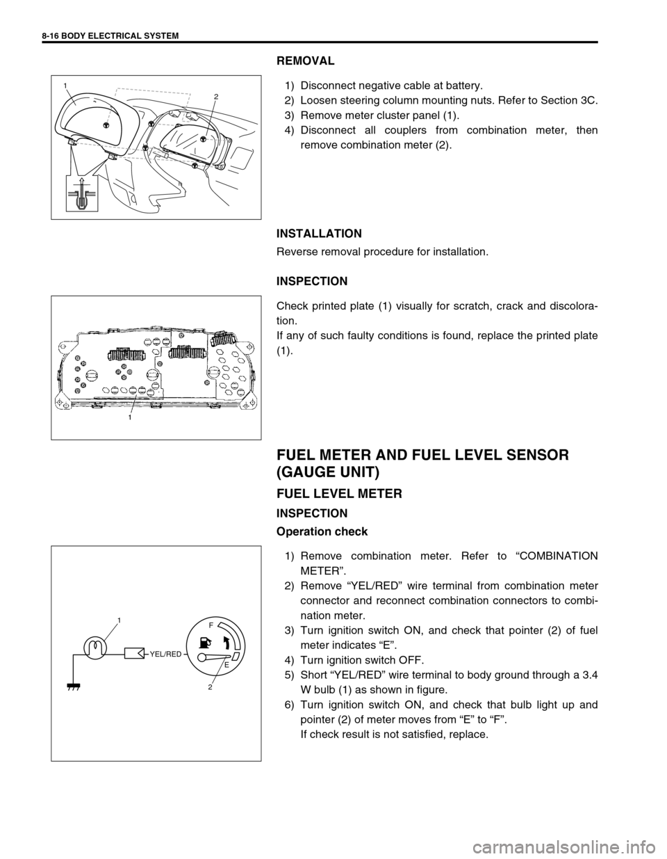
REMOVAL
1) Disconnect negative cable at battery.
2) Loosen steering column mounting nuts. Refer to Section 3C.
3) Remove meter cluster panel (1).
4) Disconnect all couplers from combination meter, then
remove combination meter (2).
INSTALLATION
Reverse removal procedure for installation.
INSPECTION
Check printed plate (1) visually for scratch, crack and discolora-
tion.
If any of such faulty conditions is found, replace the printed plate
(1).
FUEL METER AND FUEL LEVEL SENSOR
(GAUGE UNIT)
FUEL LEVEL METER
INSPECTION
Operation check
1) Remove combination meter. Refer to “COMBINATION
METER”.
2) Remove “YEL/RED” wire terminal from combination meter
connector and reconnect combination connectors to combi-
nation meter.
3) Turn ignition switch ON, and check that pointer (2) of fuel
meter indicates “E”.
4) Turn ignition switch OFF.
5) Short “YEL/RED” wire terminal to body ground through a 3.4
W bulb (1) as shown in figure.
6) Turn ignition switch ON, and check that bulb light up and
pointer (2) of meter moves from “E” to “F”.
If check result is not satisfied, replace.
1
2
YEL/REDF
E
2 1
Page 261 of 447
BODY ELECTRICAL SYSTEM 8-17
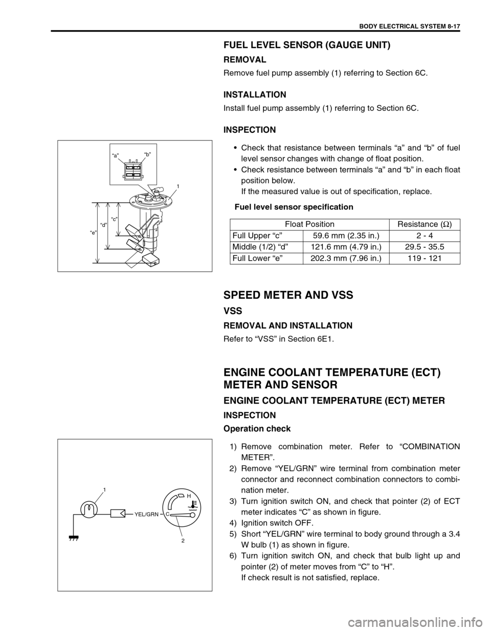
FUEL LEVEL SENSOR (GAUGE UNIT)
REMOVAL
Remove fuel pump assembly (1) referring to Section 6C.
INSTALLATION
Install fuel pump assembly (1) referring to Section 6C.
INSPECTION
Check that resistance between terminals “a” and “b” of fuel
level sensor changes with change of float position.
Check resistance between terminals “a” and “b” in each float
position below.
If the measured value is out of specification, replace.
Fuel level sensor specification
SPEED METER AND VSS
VSS
REMOVAL AND INSTALLATION
Refer to “VSS” in Section 6E1.
ENGINE COOLANT TEMPERATURE (ECT)
METER AND SENSOR
ENGINE COOLANT TEMPERATURE (ECT) METER
INSPECTION
Operation check
1) Remove combination meter. Refer to “COMBINATION
METER”.
2) Remove “YEL/GRN” wire terminal from combination meter
connector and reconnect combination connectors to combi-
nation meter.
3) Turn ignition switch ON, and check that pointer (2) of ECT
meter indicates “C” as shown in figure.
4) Ignition switch OFF.
5) Short “YEL/GRN” wire terminal to body ground through a 3.4
W bulb (1) as shown in figure.
6) Turn ignition switch ON, and check that bulb light up and
pointer (2) of meter moves from “C” to “H”.
If check result is not satisfied, replace.Float Position Resistance (Ω
)
Full Upper “c”59.6 mm (2.35 in.) 2 - 4
Middle (1/2) “d”121.6 mm (4.79 in.) 29.5 - 35.5
Full Lower “e”202.3 mm (7.96 in.) 119 - 121
“a”“b”
1
“c”
“d”
“e”
YEL/GRNC
H1
2
Page 262 of 447
8-18 BODY ELECTRICAL SYSTEM
ECT SENSOR
REMOVAL, INSTALLATION AND INSPECTION
Refer to “ECT SENSOR” in Section 6E1.
OIL PRESSURE WARNING LIGHT
OIL PRESSURE SWITCH
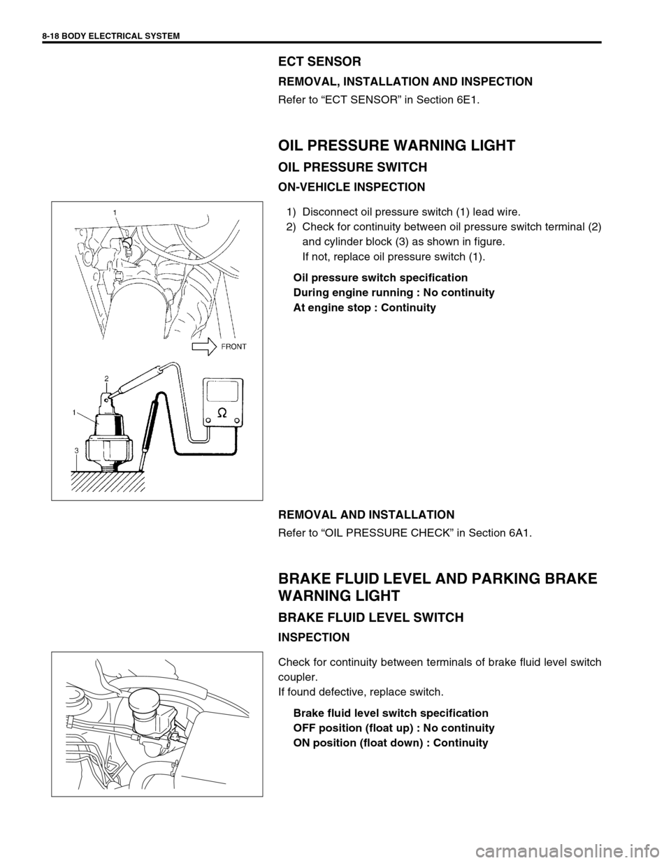
ON-VEHICLE INSPECTION
1) Disconnect oil pressure switch (1) lead wire.
2) Check for continuity between oil pressure switch terminal (2)
and cylinder block (3) as shown in figure.
If not, replace oil pressure switch (1).
Oil pressure switch specification
During engine running : No continuity
At engine stop : Continuity
REMOVAL AND INSTALLATION
Refer to “OIL PRESSURE CHECK” in Section 6A1.
BRAKE FLUID LEVEL AND PARKING BRAKE
WARNING LIGHT
BRAKE FLUID LEVEL SWITCH
INSPECTION
Check for continuity between terminals of brake fluid level switch
coupler.
If found defective, replace switch.
Brake fluid level switch specification
OFF position (float up) : No continuity
ON position (float down) : Continuity
Page 263 of 447
BODY ELECTRICAL SYSTEM 8-19
PARKING BRAKE SWITCH
INSPECTION
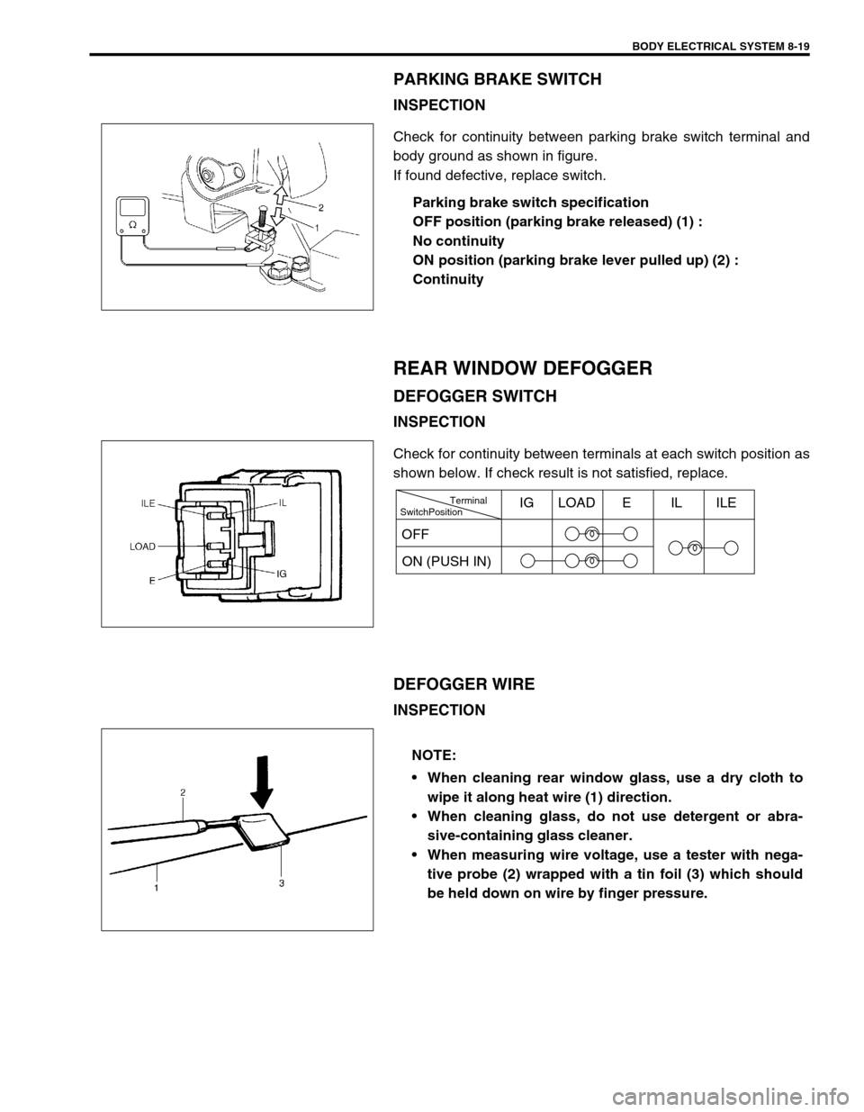
Check for continuity between parking brake switch terminal and
body ground as shown in figure.
If found defective, replace switch.
Parking brake switch specification
OFF position (parking brake released) (1) :
No continuity
ON position (parking brake lever pulled up) (2) :
Continuity
REAR WINDOW DEFOGGER
DEFOGGER SWITCH
INSPECTION
Check for continuity between terminals at each switch position as
shown below. If check result is not satisfied, replace.
DEFOGGER WIRE
INSPECTION
SwitchPositionTerminal
ON (PUSH IN)IG LOAD E IL ILE
OFF
NOTE:
When cleaning rear window glass, use a dry cloth to
wipe it along heat wire (1) direction.
When cleaning glass, do not use detergent or abra-
sive-containing glass cleaner.
When measuring wire voltage, use a tester with nega-
tive probe (2) wrapped with a tin foil (3) which should
be held down on wire by finger pressure.