ESP SUZUKI SWIFT 2000 1.G Transmission Service Workshop Manual
[x] Cancel search | Manufacturer: SUZUKI, Model Year: 2000, Model line: SWIFT, Model: SUZUKI SWIFT 2000 1.GPages: 447, PDF Size: 10.54 MB
Page 2 of 447
7A-2 MANUAL TRANSMISSION
GENERAL DESCRIPTION
CONSTRUCTION AND SERVICING
The transmission provides five forward speeds and one reverse speed by means of three synchronizers and
three shafts-input shaft, countershaft and reverse gear shaft. All forward gears are in constant mesh, and
reverse uses a sliding idler gear arrangement.
The low speed synchronizer is mounted on counter shaft and engaged with counter shaft first gear or second
gear, while the high speed synchronizer is done on input shaft and engaged with input shaft third gear or fourth
gear.
The fifth speed synchronizer on input shaft is engaged with input shaft fifth gear mounted on the input shaft.
The double cone synchronizing mechanism is provided to 2nd gear synchromesh device for high performance
of shifting to 2nd gear.
The countershaft turns the final gear and differential assembly, thereby turning the front drive shafts which are
attached to the front wheels.
4WD model is equipped with transfer assembly on transmission being mated to right side of differential output in
transmission.
For servicing, it is necessary to use genuine sealant or its equivalent on mating surfaces of transmission case
which is made of aluminum. The case fastening bolts must be tightened to specified torque by means of torque
wrench. It is also important that all parts are thoroughly cleaned with cleaning fluid and air dried before reas-
sembling.
Further, care must be taken to adjust preload of counter shaft taper roller bearings. New synchronizer rings are
prohibited from being lapped with respective gear cones by using lapping compound before they are assembled.
Page 35 of 447
MANUAL TRANSMISSION 7A-35
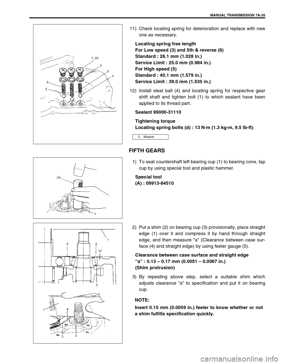
11) Check locating spring for deterioration and replace with new
one as necessary.
Locating spring free length
For Low speed (3) and 5th & reverse (6)
Standard : 26.1 mm (1.028 in.)
Service Limit : 25.0 mm (0.984 in.)
For High speed (5)
Standard : 40.1 mm (1.579 in.)
Service Limit : 39.0 mm (1.535 in.)
12) Install steel ball (4) and locating spring for respective gear
shift shaft and tighten bolt (1) to which sealant have been
applied to its thread part.
Sealant 99000-31110
Tightening torque
Locating spring bolts (d) : 13 N·m (1.3 kg-m, 9.5 Ib-ft)
FIFTH GEARS
1) To seat countershaft left bearing cup (1) to bearing cone, tap
cup by using special tool and plastic hammer.
Special tool
(A) : 09913-84510
2) Put a shim (2) on bearing cup (3) provisionally, place straight
edge (1) over it and compress it by hand through straight
edge, and then measure “a” (Clearance between case sur-
face (4) and straight edge) by using feeler gauge (5).
Clearance between case surface and straight edge
“a” : 0.13 – 0.17 mm (0.0051 – 0.0067 in.)
(Shim protrusion)
3) By repeating above step, select a suitable shim which
adjusts clearance “a” to specification and put it on bearing
cup.
2. Washer
NOTE:
Insert 0.15 mm (0.0059 in.) feeler to know whether or not
a shim fulfills specification quickly.
Page 63 of 447
AUTOMATIC TRANSMISSION (4 A/T) 7B-21
TIME LAG TEST
This test is to check conditions of clutch, reverse brake and fluid
pressure. “Time lag” means time elapsed since select lever is
shifted with engine idling till shock is felt.
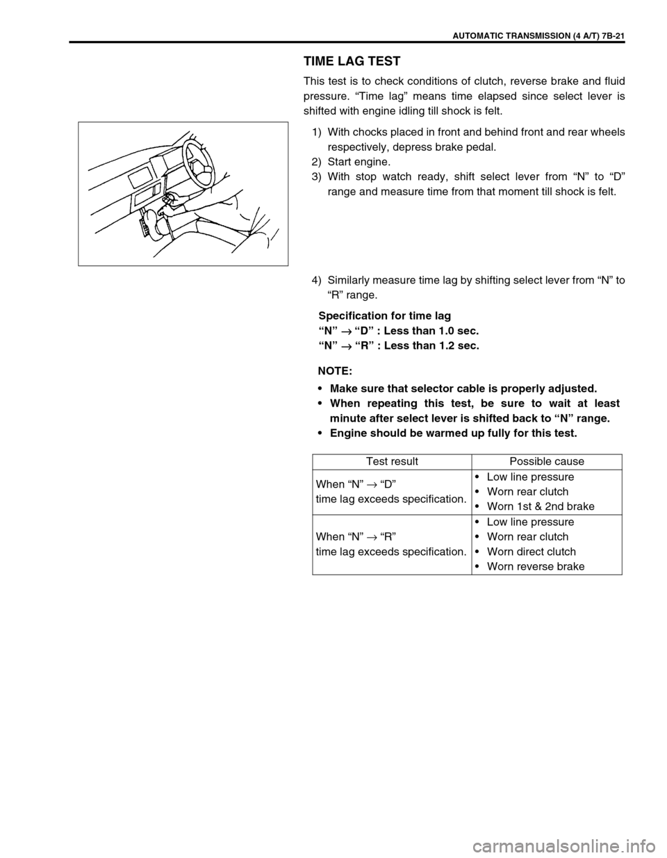
1) With chocks placed in front and behind front and rear wheels
respectively, depress brake pedal.
2) Start engine.
3) With stop watch ready, shift select lever from “N” to “D”
range and measure time from that moment till shock is felt.
4) Similarly measure time lag by shifting select lever from “N” to
“R” range.
Specification for time lag
“N”
→
→ → → “D” : Less than 1.0 sec.
“N”
→
→→ → “R” : Less than 1.2 sec.
NOTE:
Make sure that selector cable is properly adjusted.
When repeating this test, be sure to wait at least
minute after select lever is shifted back to “N” range.
Engine should be warmed up fully for this test.
Test result Possible cause
When “N” →
“D”
time lag exceeds specification.Low line pressure
Worn rear clutch
Worn 1st & 2nd brake
When “N” →
“R”
time lag exceeds specification.Low line pressure
Worn rear clutch
Worn direct clutch
Worn reverse brake
Page 255 of 447
BODY ELECTRICAL SYSTEM 8-11
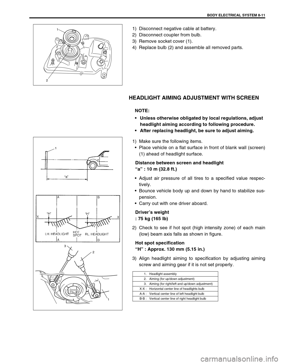
1) Disconnect negative cable at battery.
2) Disconnect coupler from bulb.
3) Remove socket cover (1).
4) Replace bulb (2) and assemble all removed parts.
HEADLIGHT AIMING ADJUSTMENT WITH SCREEN
1) Make sure the following items.
Place vehicle on a flat surface in front of blank wall (screen)
(1) ahead of headlight surface.
Distance between screen and headlight
“a” : 10 m (32.8 ft.)
Adjust air pressure of all tires to a specified value respec-
tively.
Bounce vehicle body up and down by hand to stabilize sus-
pension.
Carry out with one driver aboard.
Driver’s weight
: 75 kg (165 lb)
2) Check to see if hot spot (high intensity zone) of each main
(low) beam axis falls as shown in figure.
Hot spot specification
“H” : Approx. 130 mm (5.15 in.)
3) Align headlight aiming to specification by adjusting aiming
screw and aiming gear if it is not set properly.
21
NOTE:
Unless otherwise obligated by local regulations, adjust
headlight aiming according to following procedure.
After replacing headlight, be sure to adjust aiming.
1. Headlight assembly
2. Aiming (for up/down adjustment)
3. Aiming (for right/left and up/down adjustment)
X-X : Horizontal center line of headlights bulb
A-A : Vertical center line of left headlight bulb
B-B : Vertical center line of right headlight bulb
1 2 3
Page 268 of 447
8-24 BODY ELECTRICAL SYSTEM
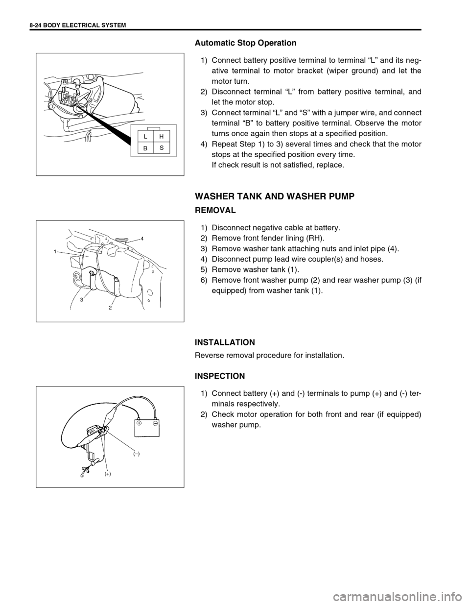
Automatic Stop Operation
1) Connect battery positive terminal to terminal “L” and its neg-
ative terminal to motor bracket (wiper ground) and let the
motor turn.
2) Disconnect terminal “L” from battery positive terminal, and
let the motor stop.
3) Connect terminal “L” and “S” with a jumper wire, and connect
terminal “B” to battery positive terminal. Observe the motor
turns once again then stops at a specified position.
4) Repeat Step 1) to 3) several times and check that the motor
stops at the specified position every time.
If check result is not satisfied, replace.
WASHER TANK AND WASHER PUMP
REMOVAL
1) Disconnect negative cable at battery.
2) Remove front fender lining (RH).
3) Remove washer tank attaching nuts and inlet pipe (4).
4) Disconnect pump lead wire coupler(s) and hoses.
5) Remove washer tank (1).
6) Remove front washer pump (2) and rear washer pump (3) (if
equipped) from washer tank (1).
INSTALLATION
Reverse removal procedure for installation.
INSPECTION
1) Connect battery (+) and (-) terminals to pump (+) and (-) ter-
minals respectively.
2) Check motor operation for both front and rear (if equipped)
washer pump.
LH
S
B
Page 269 of 447
BODY ELECTRICAL SYSTEM 8-25
REAR WIPER AND WASHER SWITCH (IF EQUIPPED)
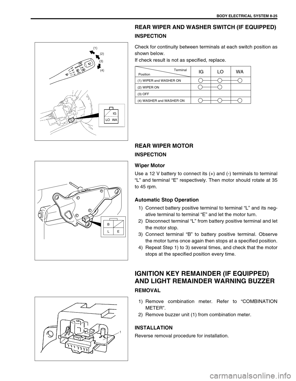
INSPECTION
Check for continuity between terminals at each switch position as
shown below.
If check result is not as specified, replace.
REAR WIPER MOTOR
INSPECTION
Wiper Motor
Use a 12 V battery to connect its (+) and (-) terminals to terminal
“L” and terminal “E” respectively. Then motor should rotate at 35
to 45 rpm.
Automatic Stop Operation
1) Connect battery positive terminal to terminal “L” and its neg-
ative terminal to terminal “E” and let the motor turn.
2) Disconnect terminal “L” from battery positive terminal and let
the motor stop.
3) Connect terminal “B” to battery positive terminal. Observe
the motor turns once again then stops at a specified position.
4) Repeat Step 1) to 3) several times, and check that the motor
stops at the specified position every time.
IGNITION KEY REMAINDER (IF EQUIPPED)
AND LIGHT REMAINDER WARNING BUZZER
REMOVAL
1) Remove combination meter. Refer to “COMBINATION
METER”.
2) Remove buzzer unit (1) from combination meter.
INSTALLATION
Reverse removal procedure for installation.
Terminal
Position
(1) WIPER and WASHER ON
(2) WIPER ON
(3) OFFIG LO WA
(4) WASHER and WASHER ON
B
E L
Page 280 of 447
8G-2 IMMOBILIZER CONTROL SYSTEM
PROCEDURE AFTER IMMOBILIZER CONTROL
MODULE REPLACEMENT ........................... 8G-24
PROCEDURE AFTER ECM
REPLACEMENT............................................ 8G-25SPECIAL TOOL ............................................ 8G-25
GENERAL DESCRIPTION
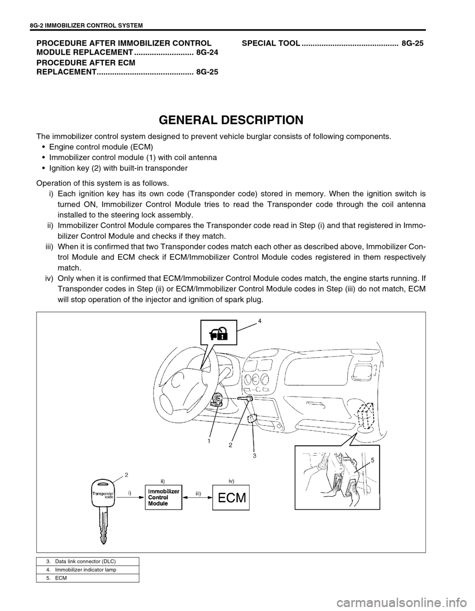
The immobilizer control system designed to prevent vehicle burglar consists of following components.
Engine control module (ECM)
Immobilizer control module (1) with coil antenna
Ignition key (2) with built-in transponder
Operation of this system is as follows.
i) Each ignition key has its own code (Transponder code) stored in memory. When the ignition switch is
turned ON, Immobilizer Control Module tries to read the Transponder code through the coil antenna
installed to the steering lock assembly.
ii) Immobilizer Control Module compares the Transponder code read in Step (i) and that registered in Immo-
bilizer Control Module and checks if they match.
iii) When it is confirmed that two Transponder codes match each other as described above, Immobilizer Con-
trol Module and ECM check if ECM/Immobilizer Control Module codes registered in them respectively
match.
iv) Only when it is confirmed that ECM/Immobilizer Control Module codes match, the engine starts running. If
Transponder codes in Step (ii) or ECM/Immobilizer Control Module codes in Step (iii) do not match, ECM
will stop operation of the injector and ignition of spark plug.
3. Data link connector (DLC)
4. Immobilizer indicator lamp
5. ECM
Page 282 of 447
8G-4 IMMOBILIZER CONTROL SYSTEM
ON-BOARD DIAGNOSTIC SYSTEM
(SELF-DIAGNOSIS FUNCTION)
Immobilizer Control Module and ECM diagnose troubles which
may occur in the area including the following parts when the igni-
tion switch is ON.
ECM :
ECM/Immobilizer Control Module code
Serial data link circuit
ECM
Immobilizer Control Module :
Transponder code
Coil antenna
ECM/Immobilizer Control Module code
Serial data link circuit
Immobilizer Control Module
Ignition signal
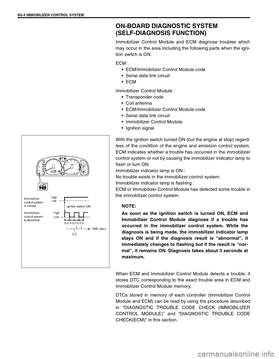
With the ignition switch turned ON (but the engine at stop) regard-
less of the condition of the engine and emission control system,
ECM indicates whether a trouble has occurred in the immobilizer
control system or not by causing the immobilizer indicator lamp to
flash or turn ON.
Immobilizer indicator lamp is ON :
No trouble exists in the immobilizer control system.
Immobilizer indicator lamp is flashing :
ECM or Immobilizer Control Module has detected some trouble in
the immobilizer control system.
When ECM and Immobilizer Control Module detects a trouble, it
stores DTC corresponding to the exact trouble area in ECM and
Immobilizer Control Module memory.
DTCs stored in memory of each controller (Immobilizer Control
Module and ECM) can be read by using the procedure described
in “DIAGNOSTIC TROUBLE CODE CHECK (IMMOBILIZER
CONTROL MODULE)” and “DIAGNOSTIC TROUBLE CODE
CHECK(ECM)” in this section. NOTE:
As soon as the ignition switch is turned ON, ECM and
Immobilizer Control Module diagnose if a trouble has
occurred in the immobilizer control system. While the
diagnosis is being made, the immobilizer indicator lamp
stays ON and if the diagnosis result is “abnormal”, it
immediately changes to flashing but if the result is “nor-
mal”, it remains ON. Diagnosis takes about 3 seconds at
maximum.
Page 287 of 447
IMMOBILIZER CONTROL SYSTEM 8G-9
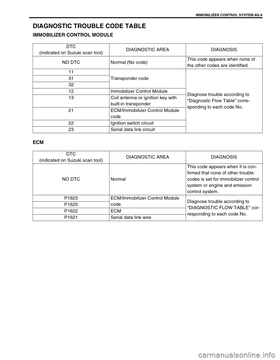
DIAGNOSTIC TROUBLE CODE TABLE
IMMOBILIZER CONTROL MODULE
ECM
DTC
(indicated on Suzuki scan tool)DIAGNOSTIC AREA DIAGNOSIS
NO DTC Normal (No code)This code appears when none of
the other codes are identified.
11
Transponder code
Diagnose trouble according to
“Diagnostic Flow Table” corre-
sponding to each code No. 31
32
12 Immobilizer Control Module
13 Coil antenna or ignition key with
built-in transponder
21 ECM/Immobilizer Control Module
code
22 Ignition switch circuit
23 Serial data link circuit
DTC
(indicated on Suzuki scan tool)DIAGNOSTIC AREA DIAGNOSIS
NO DTC NormalThis code appears when it is con-
firmed that none of other trouble
codes is set for immobilizer control
system or engine and emission
control system.
P1623 ECM/Immobilizer Control Module
codeDiagnose trouble according to
“DIAGNOSTIC FLOW TABLE” cor-
responding to each code No. P1620
P1622 ECM
P1621 Serial data link wire
Page 310 of 447
9-6 BODY SERVICE
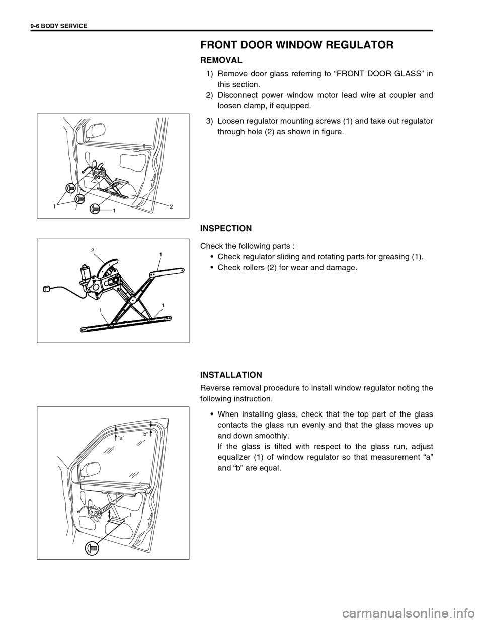
FRONT DOOR WINDOW REGULATOR
REMOVAL
1) Remove door glass referring to “FRONT DOOR GLASS” in
this section.
2) Disconnect power window motor lead wire at coupler and
loosen clamp, if equipped.
3) Loosen regulator mounting screws (1) and take out regulator
through hole (2) as shown in figure.
INSPECTION
Check the following parts :
Check regulator sliding and rotating parts for greasing (1).
Check rollers (2) for wear and damage.
INSTALLATION
Reverse removal procedure to install window regulator noting the
following instruction.
When installing glass, check that the top part of the glass
contacts the glass run evenly and that the glass moves up
and down smoothly.
If the glass is tilted with respect to the glass run, adjust
equalizer (1) of window regulator so that measurement “a”
and “b” are equal.
1
12
1 “a”“b”