Transfer SUZUKI SWIFT 2000 1.G Transmission Service Workshop Manual
[x] Cancel search | Manufacturer: SUZUKI, Model Year: 2000, Model line: SWIFT, Model: SUZUKI SWIFT 2000 1.GPages: 447, PDF Size: 10.54 MB
Page 2 of 447
7A-2 MANUAL TRANSMISSION
GENERAL DESCRIPTION
CONSTRUCTION AND SERVICING
The transmission provides five forward speeds and one reverse speed by means of three synchronizers and
three shafts-input shaft, countershaft and reverse gear shaft. All forward gears are in constant mesh, and
reverse uses a sliding idler gear arrangement.
The low speed synchronizer is mounted on counter shaft and engaged with counter shaft first gear or second
gear, while the high speed synchronizer is done on input shaft and engaged with input shaft third gear or fourth
gear.
The fifth speed synchronizer on input shaft is engaged with input shaft fifth gear mounted on the input shaft.
The double cone synchronizing mechanism is provided to 2nd gear synchromesh device for high performance
of shifting to 2nd gear.
The countershaft turns the final gear and differential assembly, thereby turning the front drive shafts which are
attached to the front wheels.
4WD model is equipped with transfer assembly on transmission being mated to right side of differential output in
transmission.
For servicing, it is necessary to use genuine sealant or its equivalent on mating surfaces of transmission case
which is made of aluminum. The case fastening bolts must be tightened to specified torque by means of torque
wrench. It is also important that all parts are thoroughly cleaned with cleaning fluid and air dried before reas-
sembling.
Further, care must be taken to adjust preload of counter shaft taper roller bearings. New synchronizer rings are
prohibited from being lapped with respective gear cones by using lapping compound before they are assembled.
Page 4 of 447
7A-4 MANUAL TRANSMISSION
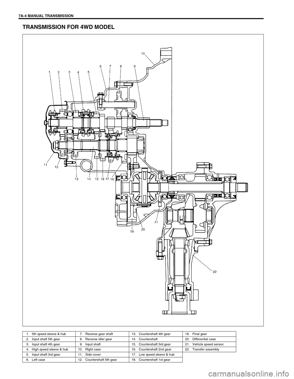
TRANSMISSION FOR 4WD MODEL
1. 5th speed sleeve & hub 7. Reverse gear shaft 13. Countershaft 4th gear 19. Final gear
2. Input shaft 5th gear 8. Reverse idler gear 14. Countershaft 20. Differential case
3. Input shaft 4th gear 9. Input shaft 15. Countershaft 3rd gear 21. Vehicle speed sensor
4. High speed sleeve & hub 10. Right case 16. Countershaft 2nd gear 22. Transfer assembly
5. Input shaft 3rd gear 11. Side cover 17. Low speed sleeve & hub
6. Left case 12. Countershaft 5th gear 18. Countershaft 1st gear
Page 6 of 447
7A-6 MANUAL TRANSMISSION
OIL CHANGE
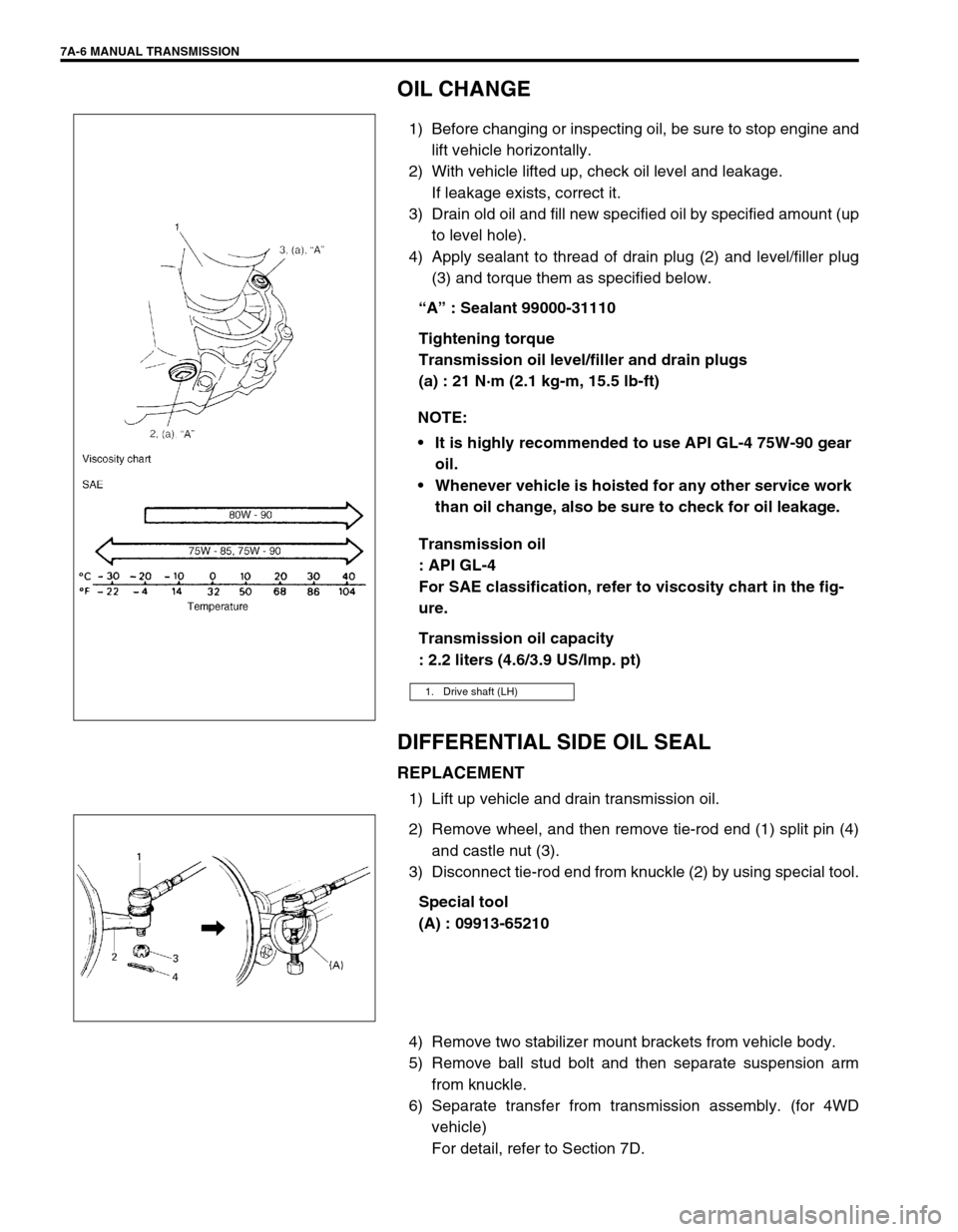
1) Before changing or inspecting oil, be sure to stop engine and
lift vehicle horizontally.
2) With vehicle lifted up, check oil level and leakage.
If leakage exists, correct it.
3) Drain old oil and fill new specified oil by specified amount (up
to level hole).
4) Apply sealant to thread of drain plug (2) and level/filler plug
(3) and torque them as specified below.
“A” : Sealant 99000-31110
Tightening torque
Transmission oil level/filler and drain plugs
(a) : 21 N·m (2.1 kg-m, 15.5 lb-ft)
Transmission oil
: API GL-4
For SAE classification, refer to viscosity chart in the fig-
ure.
Transmission oil capacity
: 2.2 liters (4.6/3.9 US/lmp. pt)
DIFFERENTIAL SIDE OIL SEAL
REPLACEMENT
1) Lift up vehicle and drain transmission oil.
2) Remove wheel, and then remove tie-rod end (1) split pin (4)
and castle nut (3).
3) Disconnect tie-rod end from knuckle (2) by using special tool.
Special tool
(A) : 09913-65210
4) Remove two stabilizer mount brackets from vehicle body.
5) Remove ball stud bolt and then separate suspension arm
from knuckle.
6) Separate transfer from transmission assembly. (for 4WD
vehicle)
For detail, refer to Section 7D. NOTE:
It is highly recommended to use API GL-4 75W-90 gear
oil.
Whenever vehicle is hoisted for any other service work
than oil change, also be sure to check for oil leakage.
1. Drive shaft (LH)
Page 16 of 447
7A-16 MANUAL TRANSMISSION
TRANSMISSION UNIT
DISMOUNTING
Under Hood
1) Disconnect negative cable at battery.
2) Undo wiring harness clamps, disconnect backup lamp switch
coupler, VSS coupler and ground cable.
3) Disconnect clutch cable from clutch release lever and
bracket.
4) Disconnect gear shift and select control cables.
5) Remove water pipe bracket bolts from transmission.
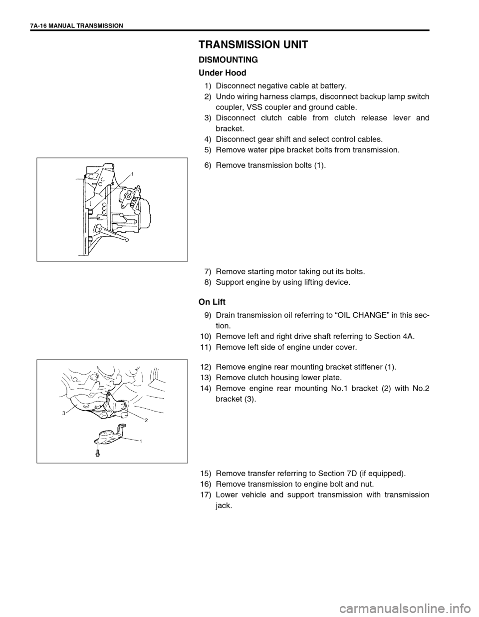
6) Remove transmission bolts (1).
7) Remove starting motor taking out its bolts.
8) Support engine by using lifting device.
On Lift
9) Drain transmission oil referring to “OIL CHANGE” in this sec-
tion.
10) Remove left and right drive shaft referring to Section 4A.
11) Remove left side of engine under cover.
12) Remove engine rear mounting bracket stiffener (1).
13) Remove clutch housing lower plate.
14) Remove engine rear mounting No.1 bracket (2) with No.2
bracket (3).
15) Remove transfer referring to Section 7D (if equipped).
16) Remove transmission to engine bolt and nut.
17) Lower vehicle and support transmission with transmission
jack.
Page 17 of 447
MANUAL TRANSMISSION 7A-17
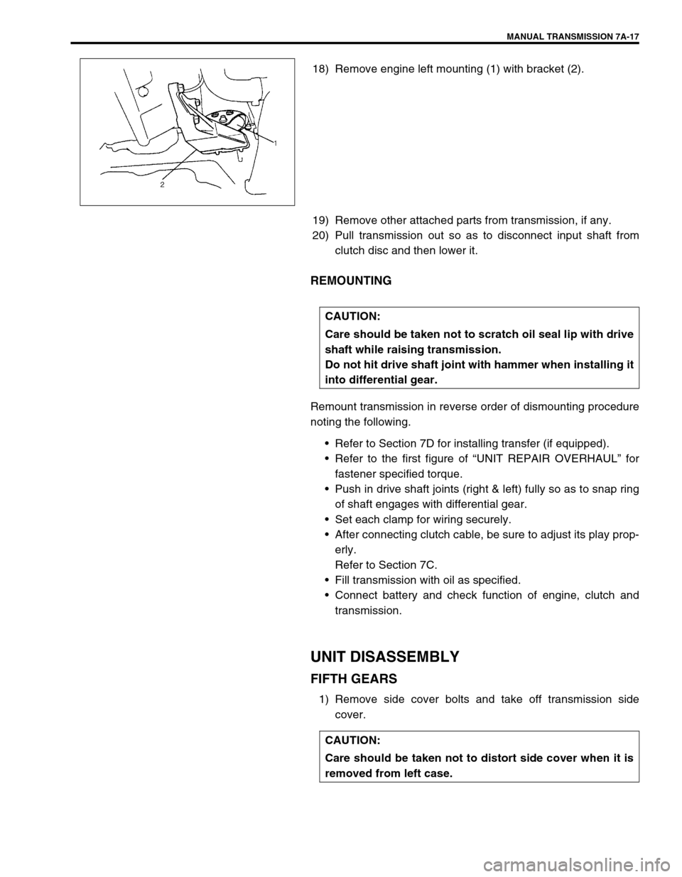
18) Remove engine left mounting (1) with bracket (2).
19) Remove other attached parts from transmission, if any.
20) Pull transmission out so as to disconnect input shaft from
clutch disc and then lower it.
REMOUNTING
Remount transmission in reverse order of dismounting procedure
noting the following.
Refer to Section 7D for installing transfer (if equipped).
Refer to the first figure of “UNIT REPAIR OVERHAUL” for
fastener specified torque.
Push in drive shaft joints (right & left) fully so as to snap ring
of shaft engages with differential gear.
Set each clamp for wiring securely.
After connecting clutch cable, be sure to adjust its play prop-
erly.
Refer to Section 7C.
Fill transmission with oil as specified.
Connect battery and check function of engine, clutch and
transmission.
UNIT DISASSEMBLY
FIFTH GEARS
1) Remove side cover bolts and take off transmission side
cover.
CAUTION:
Care should be taken not to scratch oil seal lip with drive
shaft while raising transmission.
Do not hit drive shaft joint with hammer when installing it
into differential gear.
CAUTION:
Care should be taken not to distort side cover when it is
removed from left case.
Page 110 of 447

7B-68 AUTOMATIC TRANSMISSION (4 A/T)
DIFFERENTIAL SIDE OIL SEAL
REPLACEMENT
1) Lift up vehicle and drain transmission oil.
2) Remove drive shaft joints from differential gear of transmis-
sion.
Refer to Section 4 for procedure to disconnect drive shaft
joints.
For differential side oil seal removal, it is not necessary to
remove drive shafts from steering knuckle.
For 4WD vehicle, remove transfer referring to Section 7D.
3) Remove differential side oil seal (1) by using flat end rod or
like.
4) Install new differential side oil seal by using special tool.
Special tool
(A) : 09940-53111
(B) : 09913-75510
5) Install drive shaft referring to Section 4.
6) Refill A/T fluid referring to “FLUID CHANGE” in this section. NOTE:
For oil seal installation, press-fit oil seal so that transmis-
sion case end face is flush with oil seal end face.
2. Steering gear box
3. A/T oil pan
4. Torque converter hous-
ing
5. Transmission case
Page 118 of 447

7B-76 AUTOMATIC TRANSMISSION (4 A/T)
DISMOUNTING
1) Take down transmission with engine. For its procedure, refer
to Section 6A1.
2) For 4WD vehicle, remove transfer referring to Section 7D
For 2WD vehicle, remove engine rear mounting No.1
bracket and engine rear mounting No.2 bracket with stiff-
ener.
3) Remove torque converter housing lower plate (1).
4) Remove drive plate bolts.
To lock drive plate (1), engage a flat head rod or the like (2)
with drive plate gear.
5) Remove starting motor.
6) Remove bolts and nut fastening engine and transmission,
then detach transmission from engine.
NOTE:
When detaching transmission from engine, move it in
parallel with crankshaft and use care so as not to apply
excessive force to drive plate and torque converter.
WARNING:
Be sure to keep transmission with torque converter hori-
zontal or facing up throughout the work. Should it be
tilted with torque converter down, converter may fall off
and cause personal injury.
Page 119 of 447

AUTOMATIC TRANSMISSION (4 A/T) 7B-77
REMOUNTING
1) Make sure that torque converter is installed correctly to
transmission.
Refer to “UNIT ASSEMBLY” in this section.
2) Attach transmission to engine.
Tightening torque
Transmission to engine bolts and nut
(a) : 85 N·m (8.5 kg-m, 61.5 lb-ft)
3) Tighten drive plate-torque converter bolts.
Align drive plate bolt hole and torque converter through
starter motor mounting opening then tighten bolts through
torque converter housing lower plate opening.
Lock drive plate (1) by engaging a flat head rod or the like (2)
with drive plate gear.
Tightening torque
Drive plate to torque converter bolts
(a) : 20 N·m (2.0 kg-m, 14.5 lb-ft)
4) Install torque converter housing lower plate (1).
5) Install starter motor.
Tightening Torque
Starter motor bolts : 23 N·m (2.3 kg-m, 16.5 lb-ft)
6) For 4WD vehicle, install transfer referring to Section 7D.
For 2WD vehicle, install engine rear mounting brackets and
stiffener.
7) Remount engine with transmission assembly to vehicle.
Refer to Section 6A1 for its procedure. WARNING:
Be sure to keep transmission with torque converter hori-
zontal or facing up throughout the work. Should it be
tilted with torque converter down, converter may fall off
and cause personal injury.
3. Wrench
4. Engine oil pan
Page 199 of 447

TRANSFER 7D-1
6F1
6F2
6G
6H
6K
7A
7A1
7B1
7C1
7E
7F
7D
8A
8B
8C
8D
8E
9
10
10A
10B
SECTION 7D
TRANSFER
CONTENTS
GENERAL DESCRIPTION ...............................7D-2
DIAGNOSIS ......................................................7D-2
ON-VEHICLE SERVICE ...................................7D-3
UNIT REPAIR OVERHAUL ..............................7D-4
UNIT DISMOUNTING ...................................7D-5
UNIT DISASSEMBLY ...................................7D-6
TRANSFER ASSEMBLY...........................7D-6
REDUCTION DRIVEN GEAR ...................7D-7
INTERMEDIATE SHAFT ...........................7D-8
TRANSFER OUTPUT RETAINER ............7D-9
COMPONENT INSPECTION ......................7D-10
UNIT ASSEMBLY .......................................7D-10REDUCTION DRIVEN GEAR ................. 7D-10
BEVEL GEAR SHIM ............................... 7D-11
TRANSFER OUTPUT RETAINER .......... 7D-12
RIGHT CASE .......................................... 7D-16
LEFT CASE............................................. 7D-17
TRANSFER ASSEMBLY ........................ 7D-17
BEVEL GEAR BACK LASH .................... 7D-18
UNIT INSTALLATION ................................. 7D-20
TIGHTENING TORQUE SPECIFICATION..... 7D-22
REQUIRED SERVICE MATERIAL................. 7D-22
SPECIAL TOOL ............................................. 7D-22
Page 200 of 447

7D-2 TRANSFER
GENERAL DESCRIPTION
The transfer consists of parts as shown in figure.
DIAGNOSIS
1. Intermediate shaft 6. Shim 11. Transfer output retainer
2. Left case 7. Reduction driven gear 12. Flange
3. Reduction drive gear 8. Bevel gear✱
:Forward
4. Circlip 9. Bevel pinion shaft
5. Right case 10. Pinion shaft spacer
Condition Possible Cause Correction
Noise
Inadequate or insufficient lubricant Replenish.
Damaged or worn bearing(s) Replace.
Damaged or worn gear(s) Replace.
Damaged or worn chamfered tooth on sleeve or
gearReplace.
Preload of taper roller bearing is reduced Adjust.