four wheel drive SUZUKI SWIFT 2000 1.G Transmission Service Workshop Manual
[x] Cancel search | Manufacturer: SUZUKI, Model Year: 2000, Model line: SWIFT, Model: SUZUKI SWIFT 2000 1.GPages: 447, PDF Size: 10.54 MB
Page 2 of 447

7A-2 MANUAL TRANSMISSION
GENERAL DESCRIPTION
CONSTRUCTION AND SERVICING
The transmission provides five forward speeds and one reverse speed by means of three synchronizers and
three shafts-input shaft, countershaft and reverse gear shaft. All forward gears are in constant mesh, and
reverse uses a sliding idler gear arrangement.
The low speed synchronizer is mounted on counter shaft and engaged with counter shaft first gear or second
gear, while the high speed synchronizer is done on input shaft and engaged with input shaft third gear or fourth
gear.
The fifth speed synchronizer on input shaft is engaged with input shaft fifth gear mounted on the input shaft.
The double cone synchronizing mechanism is provided to 2nd gear synchromesh device for high performance
of shifting to 2nd gear.
The countershaft turns the final gear and differential assembly, thereby turning the front drive shafts which are
attached to the front wheels.
4WD model is equipped with transfer assembly on transmission being mated to right side of differential output in
transmission.
For servicing, it is necessary to use genuine sealant or its equivalent on mating surfaces of transmission case
which is made of aluminum. The case fastening bolts must be tightened to specified torque by means of torque
wrench. It is also important that all parts are thoroughly cleaned with cleaning fluid and air dried before reas-
sembling.
Further, care must be taken to adjust preload of counter shaft taper roller bearings. New synchronizer rings are
prohibited from being lapped with respective gear cones by using lapping compound before they are assembled.
Page 184 of 447

7C-2 CLUTCH
GENERAL DESCRIPTION
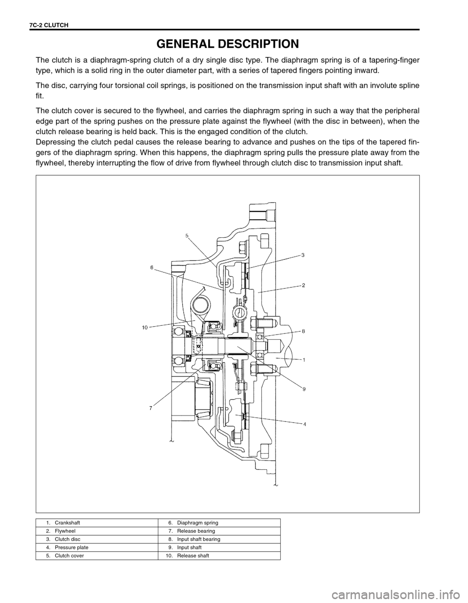
The clutch is a diaphragm-spring clutch of a dry single disc type. The diaphragm spring is of a tapering-finger
type, which is a solid ring in the outer diameter part, with a series of tapered fingers pointing inward.
The disc, carrying four torsional coil springs, is positioned on the transmission input shaft with an involute spline
fit.
The clutch cover is secured to the flywheel, and carries the diaphragm spring in such a way that the peripheral
edge part of the spring pushes on the pressure plate against the flywheel (with the disc in between), when the
clutch release bearing is held back. This is the engaged condition of the clutch.
Depressing the clutch pedal causes the release bearing to advance and pushes on the tips of the tapered fin-
gers of the diaphragm spring. When this happens, the diaphragm spring pulls the pressure plate away from the
flywheel, thereby interrupting the flow of drive from flywheel through clutch disc to transmission input shaft.
1. Crankshaft 6. Diaphragm spring
2. Flywheel 7. Release bearing
3. Clutch disc 8. Input shaft bearing
4. Pressure plate 9. Input shaft
5. Clutch cover 10. Release shaft