checking oil SUZUKI SWIFT 2000 1.G Transmission Service Workshop Manual
[x] Cancel search | Manufacturer: SUZUKI, Model Year: 2000, Model line: SWIFT, Model: SUZUKI SWIFT 2000 1.GPages: 447, PDF Size: 10.54 MB
Page 52 of 447

7B-10 AUTOMATIC TRANSMISSION (4 A/T)
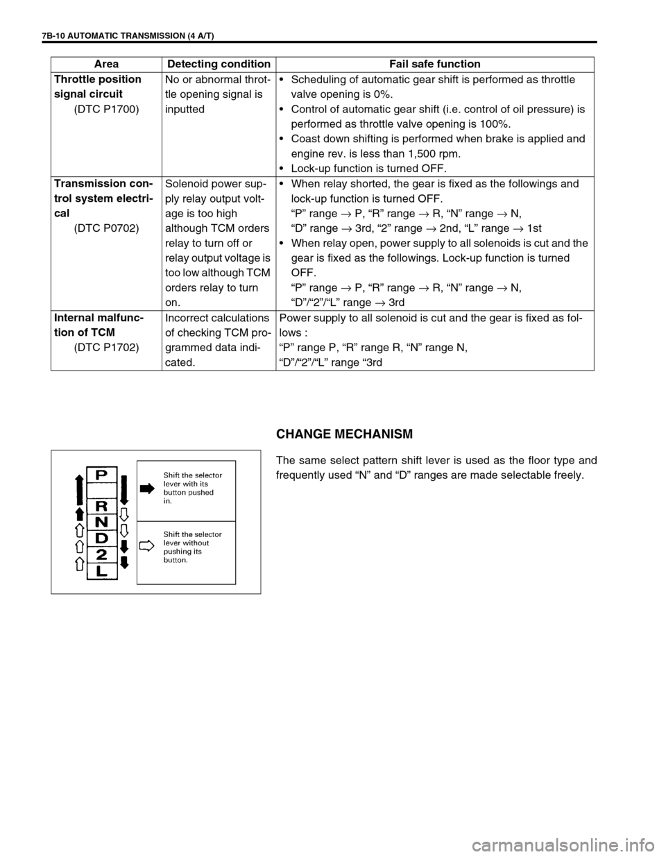
CHANGE MECHANISM
The same select pattern shift lever is used as the floor type and
frequently used “N” and “D” ranges are made selectable freely. Throttle position
signal circuit
(DTC P1700)No or abnormal throt-
tle opening signal is
inputtedScheduling of automatic gear shift is performed as throttle
valve opening is 0%.
Control of automatic gear shift (i.e. control of oil pressure) is
performed as throttle valve opening is 100%.
Coast down shifting is performed when brake is applied and
engine rev. is less than 1,500 rpm.
Lock-up function is turned OFF.
Transmission con-
trol system electri-
cal
(DTC P0702)Solenoid power sup-
ply relay output volt-
age is too high
although TCM orders
relay to turn off or
relay output voltage is
too low although TCM
orders relay to turn
on.When relay shorted, the gear is fixed as the followings and
lock-up function is turned OFF.
“P” range →
P, “R” range →
R, “N” range →
N,
“D” range →
3rd, “2” range →
2nd, “L” range →
1st
When relay open, power supply to all solenoids is cut and the
gear is fixed as the followings. Lock-up function is turned
OFF.
“P” range →
P, “R” range →
R, “N” range →
N,
“D”/“2”/“L” range →
3rd
Internal malfunc-
tion of TCM
(DTC P1702)Incorrect calculations
of checking TCM pro-
grammed data indi-
cated.Power supply to all solenoid is cut and the gear is fixed as fol-
lows :
“P” range P, “R” range R, “N” range N,
“D”/“2”/“L” range “3rd Area Detecting condition Fail safe function
Page 58 of 447

7B-16 AUTOMATIC TRANSMISSION (4 A/T)
2. DIAGNOSTIC TROUBLE CODE (DTC) CHECK, RECORD AND CLEARANCE
To check DTC, refer to “DTC CHECK” in this section. When a DTC exists, it means existence of a malfunction in
the system represented by that code but whether it still exists (current) or it occurred in the past and has gone
(history) is unknown. To know it, clear this DTC once (Refer to “DTC CLEARANCE” in this section.), perform
test drive and/or “TROUBLE SYMPTOM CONFIRMATION” in this section and then check DTC again as
described in “DTC CHECK”. Attempt to diagnose the trouble based on the DTC recorded in this step only or fail-
ure to clear the DTC in this step may mislead the diagnosis or make diagnosing difficult. Even after checking the
DTC with the SUZUKI scan tool, diagnosis should be performed according to this flow chart to check TCM for
proper self-diagnosis function.
3 and 4. VISUAL INSPECTION
As a preliminary step, perform visual check of the following items that support proper function of the automatic
transmission.
5.TROUBLE SYMPTOM CONFIRMATION
Check if what the customer claimed in “CUSTOMER COMPLAINT ANALYSIS” is actually found in the vehicle
and if that symptom is found, whether it is identified as a failure. (This step should be shared with the customer
if possible.)
When the symptom is not actually found, possibility is :
The symptom occurs under certain conditions.
----- Retry with the vehicle under different conditions.
The trouble occurred only temporarily and normal operation has been restored.
----- Perform “DTC CHECK” and if the diagnostic trouble code is indicated, inspect according to the flow
table for that DTC.
6 and 7. RECHECKING AND RECORD OF DTC
Refer to “DTC CHECK” in this section.INSPECTION ITEM REFERRING SECTION
Engine oil ----- level, leakage Section 0B
Engine coolant ----- level, leakage Section 0B
A/T fluid ----- level, leakage, color Section 0B
Battery ----- fluid level, corrosion of terminal
A/T fluid hoses ----- disconnection, looseness, deterioration
Connectors of electric wire harness ----- disconnection, friction Section 8
Fuses ----- burning Section 8
Parts ----- installation, bolt ----- looseness
Parts ----- deformation
Other parts that can be checked visually
Also add following items at engine start.
Indicator, warning lights in combination meter ----- ON
(indicating abnormality in system) or OFFSection 8C
Other parts that can be checked visually
Page 98 of 447

7B-56 AUTOMATIC TRANSMISSION (4 A/T)
FLUID LEVEL AT ROOM TEMPERATURE
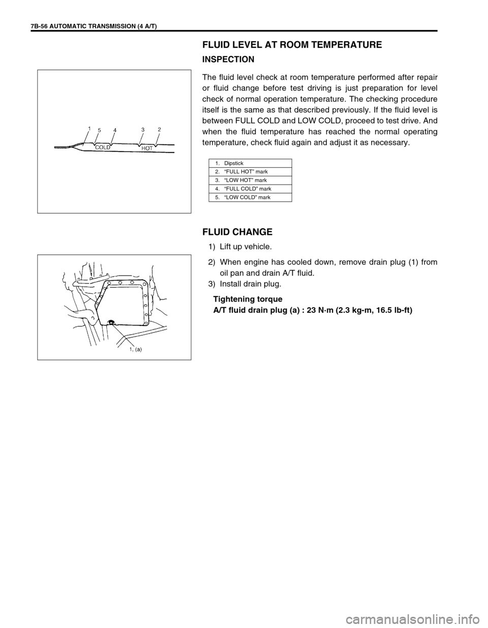
INSPECTION
The fluid level check at room temperature performed after repair
or fluid change before test driving is just preparation for level
check of normal operation temperature. The checking procedure
itself is the same as that described previously. If the fluid level is
between FULL COLD and LOW COLD, proceed to test drive. And
when the fluid temperature has reached the normal operating
temperature, check fluid again and adjust it as necessary.
FLUID CHANGE
1) Lift up vehicle.
2) When engine has cooled down, remove drain plug (1) from
oil pan and drain A/T fluid.
3) Install drain plug.
Tightening torque
A/T fluid drain plug (a) : 23 N·m (2.3 kg-m, 16.5 lb-ft)
1. Dipstick
2.“FULL HOT” mark
3.“LOW HOT” mark
4.“FULL COLD” mark
5.“LOW COLD” mark
Page 283 of 447

IMMOBILIZER CONTROL SYSTEM 8G-5
DIAGNOSIS
PRECAUTIONS IN DIAGNOSING TROUBLES
PRECAUTIONS IN IDENTIFYING DIAGNOSTIC TROUBLE CODE
ECM
Before identifying diagnostic trouble code indicated through Suzuki scan tool, don't disconnect couplers from
ECM, battery cable from battery, ECM ground wire harness from engine.
Such disconnection will clear trouble codes for engine and emission control system and immobilizer control
system stored in memory of ECM.
Take a note of diagnostic trouble code indicated first.
IMMOBILIZER CONTROL MODULE
Take a note of diagnostic trouble code indicated first.
INTERMITTENT TROUBLES
There is case where Suzuki scan tool indicate a diagnostic trouble code representing a trouble which
occurred only temporarily and has gone. In such case, it may occur that good parts are replaced unneces-
sarily. To prevent such accident, be sure to follow instructions given below when checking by using “Diag-
nostic Flow Table”.
–When trouble can be identified, it is not an intermittent one :
Check coil antenna, ignition key, wires and each connection and if they are all in good condition, substi-
tute a known-good ECM and recheck.
–When trouble can not be identified but Suzuki scan tool indicate a trouble code :
Diagnose trouble by using that code No. and if ignition key, coil antenna, wires and each connection are
all in good condition, turn OFF ignition switch and then ON.
Then check what Suzuki scan tool indicate.Only when they indicate trouble code again, substitute a known-
good ECM or Immobilizer Control Module and check again.
If they indicate not trouble code but normal code, it means that an intermittent trouble did occur and has gone. In
this case, check wires and connections carefully again.
Page 422 of 447

10B-48 AIR BAG SYSTEM
3) If equipped with passenger air bag (inflator) module, connect
Yellow connector (1) of passenger air bag (inflator) module,
and be sure to lock connector with lock lever.
a) Connect connector.
b) Lock connector with lock lever.
4) Install glove box.
5) Install “AIR BAG” fuse to fuse box.
6) Turn ignition switch to ON position and verify that “AIR BAG”
warning lamp flashes 6 times and then turns OFF.
If it does not operate as described, perform “AIR BAG DIAG-
NOSTIC SYSTEM CHECK”.
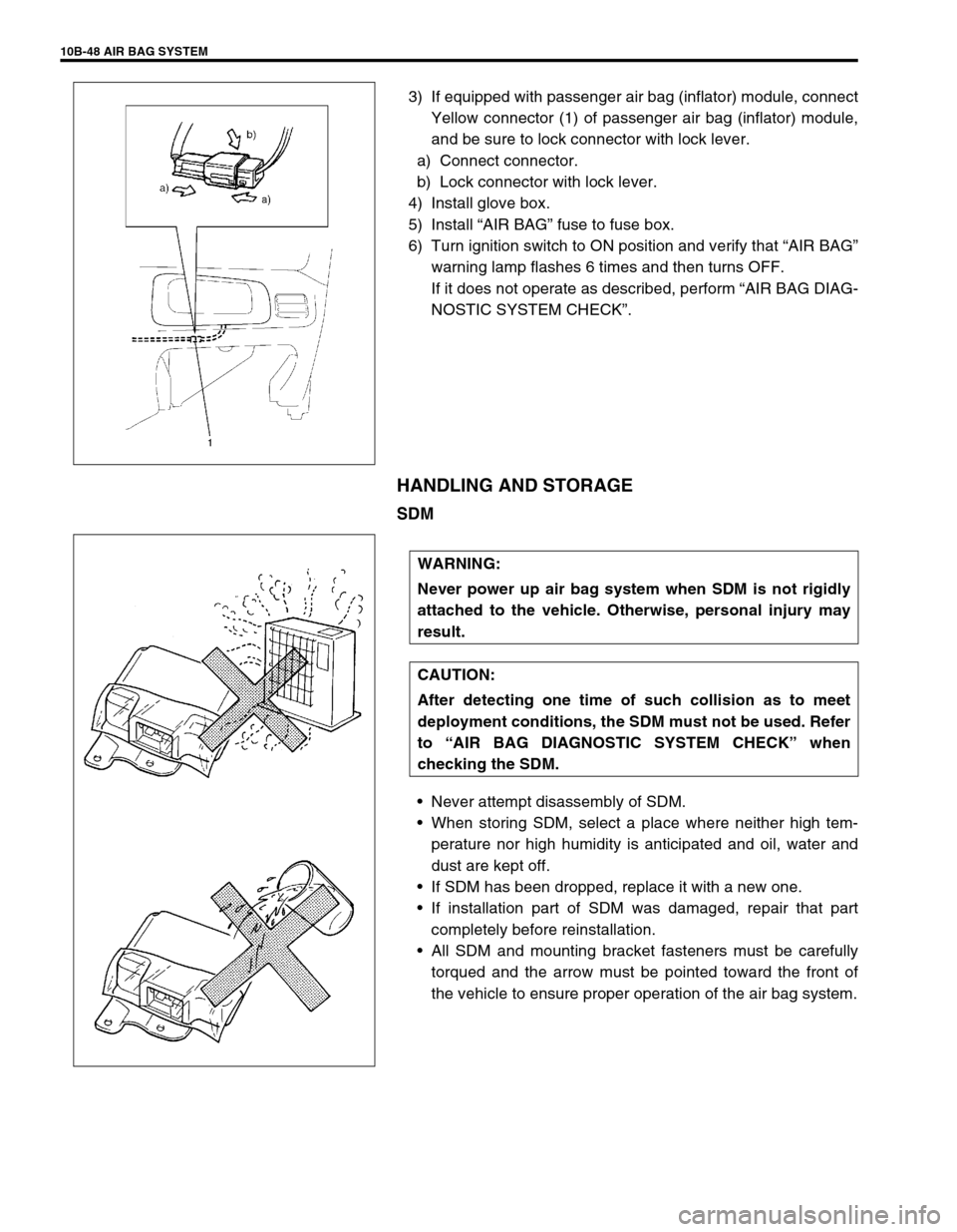
HANDLING AND STORAGE
SDM
Never attempt disassembly of SDM.
When storing SDM, select a place where neither high tem-
perature nor high humidity is anticipated and oil, water and
dust are kept off.
If SDM has been dropped, replace it with a new one.
If installation part of SDM was damaged, repair that part
completely before reinstallation.
All SDM and mounting bracket fasteners must be carefully
torqued and the arrow must be pointed toward the front of
the vehicle to ensure proper operation of the air bag system.
WARNING:
Never power up air bag system when SDM is not rigidly
attached to the vehicle. Otherwise, personal injury may
result.
CAUTION:
After detecting one time of such collision as to meet
deployment conditions, the SDM must not be used. Refer
to “AIR BAG DIAGNOSTIC SYSTEM CHECK” when
checking the SDM.
Page 427 of 447

AIR BAG SYSTEM 10B-53
REPAIRS AND INSPECTIONS REQUIRED AFTER AN ACCIDENT
ACCIDENT WITH DEPLOYMENT/ACTIVA-
TION - COMPONENT REPLACEMENT
The following components must be replaced.
Driver and passenger air bag (inflator) modules
Driver and passenger seat belt pretensioners
SDM
–Replace with new one as an assembly.
ACCIDENT WITH OR WITHOUT DEPLOY-
MENT/ACTIVATION - COMPONENT INSPEC-
TIONS
Certain air bag system components must be inspected after any
crash, whether the air bag system activated or not.
Those components are :
Steering column (1) and shaft joints
–Check for length, damage and bend according to “CHECK-
ING STEERING COLUMN FOR ACCIDENT DAMAGE” in
SECTION 3C.
If any faulty condition is found in above checks, replace faulty
part.
Steering column bracket (2) and capsules (3)
–Check for damage and bent.
If any faulty condition is found in above checks, replace faulty
part. CAUTION:
All air bag system components, including the electrical harness (component mounting points),
must be inspected after an accident. If any components are damaged or bent, they must be
replaced even if air bag system activation did not occur.
Never use air bag system parts from another vehicle.
Do not attempt to service the parts below. Service of these parts is by replacement only.
–Driver/Passenger air bag (inflator) module, Driver/Passenger seat belt pretensioner
–SDM
–Contact coil and combination switch assembly
–Air bag wire harness
Proper operation of the air bag system requires that any repairs to the vehicle structure return it to
its original production configuration.
CAUTION:
After detecting one time of such collision as to meet deployment conditions, the SDM must not be
used. Refer to “AIR BAG DIAGNOSTIC SYSTEM CHECK” when checking the SDM.