drain bolt SUZUKI SWIFT 2000 1.G Transmission Service Workshop Manual
[x] Cancel search | Manufacturer: SUZUKI, Model Year: 2000, Model line: SWIFT, Model: SUZUKI SWIFT 2000 1.GPages: 447, PDF Size: 10.54 MB
Page 6 of 447
7A-6 MANUAL TRANSMISSION
OIL CHANGE
1) Before changing or inspecting oil, be sure to stop engine and
lift vehicle horizontally.
2) With vehicle lifted up, check oil level and leakage.
If leakage exists, correct it.
3) Drain old oil and fill new specified oil by specified amount (up
to level hole).
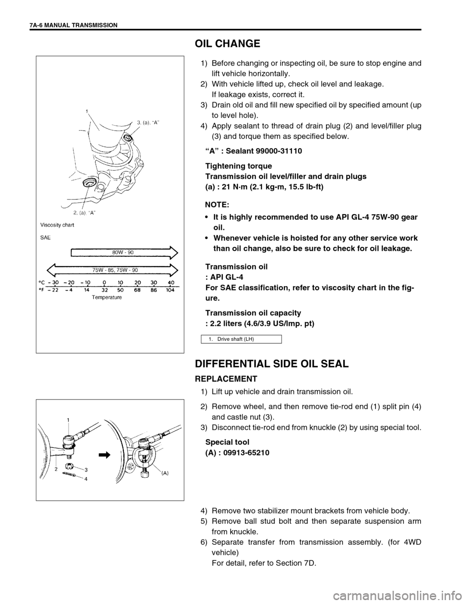
4) Apply sealant to thread of drain plug (2) and level/filler plug
(3) and torque them as specified below.
“A” : Sealant 99000-31110
Tightening torque
Transmission oil level/filler and drain plugs
(a) : 21 N·m (2.1 kg-m, 15.5 lb-ft)
Transmission oil
: API GL-4
For SAE classification, refer to viscosity chart in the fig-
ure.
Transmission oil capacity
: 2.2 liters (4.6/3.9 US/lmp. pt)
DIFFERENTIAL SIDE OIL SEAL
REPLACEMENT
1) Lift up vehicle and drain transmission oil.
2) Remove wheel, and then remove tie-rod end (1) split pin (4)
and castle nut (3).
3) Disconnect tie-rod end from knuckle (2) by using special tool.
Special tool
(A) : 09913-65210
4) Remove two stabilizer mount brackets from vehicle body.
5) Remove ball stud bolt and then separate suspension arm
from knuckle.
6) Separate transfer from transmission assembly. (for 4WD
vehicle)
For detail, refer to Section 7D. NOTE:
It is highly recommended to use API GL-4 75W-90 gear
oil.
Whenever vehicle is hoisted for any other service work
than oil change, also be sure to check for oil leakage.
1. Drive shaft (LH)
Page 12 of 447
7A-12 MANUAL TRANSMISSION
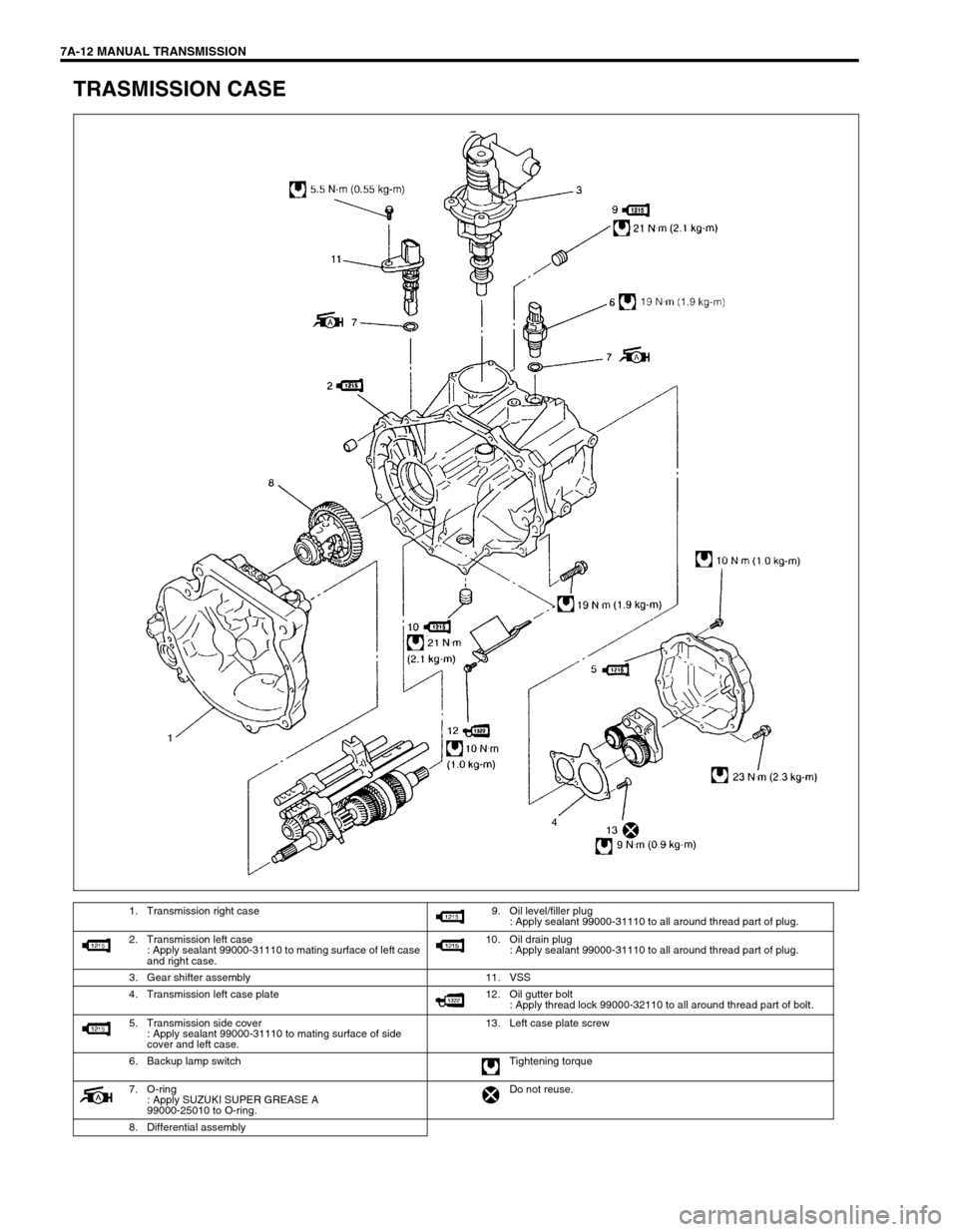
TRASMISSION CASE
1. Transmission right case 9. Oil level/filler plug
: Apply sealant 99000-31110 to all around thread part of plug.
2. Transmission left case
: Apply sealant 99000-31110 to mating surface of left case
and right case.10. Oil drain plug
: Apply sealant 99000-31110 to all around thread part of plug.
3. Gear shifter assembly 11. VSS
4. Transmission left case plate 12. Oil gutter bolt
: Apply thread lock 99000-32110 to all around thread part of bolt.
5. Transmission side cover
: Apply sealant 99000-31110 to mating surface of side
cover and left case.13. Left case plate screw
6. Backup lamp switch Tightening torque
7. O-ring
: Apply SUZUKI SUPER GREASE A
99000-25010 to O-ring.Do not reuse.
8. Differential assembly
Page 16 of 447
7A-16 MANUAL TRANSMISSION
TRANSMISSION UNIT
DISMOUNTING
Under Hood
1) Disconnect negative cable at battery.
2) Undo wiring harness clamps, disconnect backup lamp switch
coupler, VSS coupler and ground cable.
3) Disconnect clutch cable from clutch release lever and
bracket.
4) Disconnect gear shift and select control cables.
5) Remove water pipe bracket bolts from transmission.
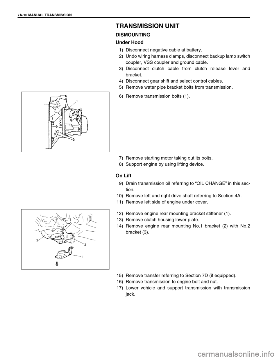
6) Remove transmission bolts (1).
7) Remove starting motor taking out its bolts.
8) Support engine by using lifting device.
On Lift
9) Drain transmission oil referring to “OIL CHANGE” in this sec-
tion.
10) Remove left and right drive shaft referring to Section 4A.
11) Remove left side of engine under cover.
12) Remove engine rear mounting bracket stiffener (1).
13) Remove clutch housing lower plate.
14) Remove engine rear mounting No.1 bracket (2) with No.2
bracket (3).
15) Remove transfer referring to Section 7D (if equipped).
16) Remove transmission to engine bolt and nut.
17) Lower vehicle and support transmission with transmission
jack.
Page 39 of 447
MANUAL TRANSMISSION 7A-39
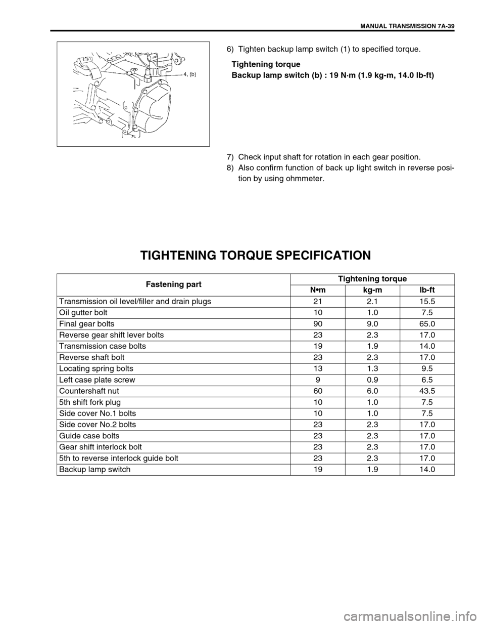
6) Tighten backup lamp switch (1) to specified torque.
Tightening torque
Backup lamp switch (b) : 19 N·m (1.9 kg-m, 14.0 lb-ft)
7) Check input shaft for rotation in each gear position.
8) Also confirm function of back up light switch in reverse posi-
tion by using ohmmeter.
TIGHTENING TORQUE SPECIFICATION
Fastening partTightening torque
Nm kg-m lb-ft
Transmission oil level/filler and drain plugs 21 2.1 15.5
Oil gutter bolt 10 1.0 7.5
Final gear bolts 90 9.0 65.0
Reverse gear shift lever bolts 23 2.3 17.0
Transmission case bolts 19 1.9 14.0
Reverse shaft bolt 23 2.3 17.0
Locating spring bolts 13 1.3 9.5
Left case plate screw 9 0.9 6.5
Countershaft nut 60 6.0 43.5
5th shift fork plug 10 1.0 7.5
Side cover No.1 bolts 10 1.0 7.5
Side cover No.2 bolts 23 2.3 17.0
Guide case bolts 23 2.3 17.0
Gear shift interlock bolt 23 2.3 17.0
5th to reverse interlock guide bolt 23 2.3 17.0
Backup lamp switch 19 1.9 14.0
Page 40 of 447
7A-40 MANUAL TRANSMISSION
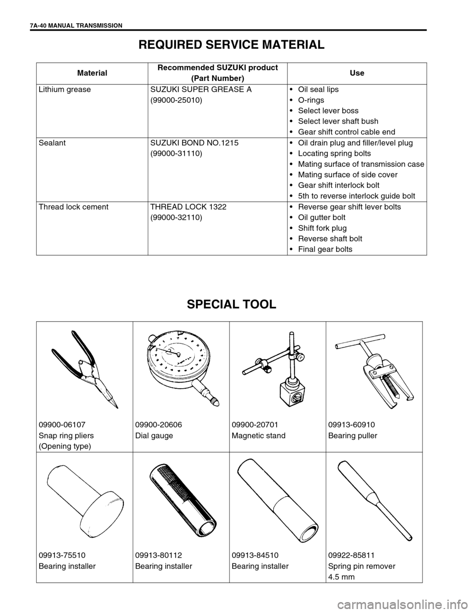
REQUIRED SERVICE MATERIAL
SPECIAL TOOL
MaterialRecommended SUZUKI product
(Part Number)Use
Lithium grease SUZUKI SUPER GREASE A
(99000-25010) Oil seal lips
O-rings
Select lever boss
Select lever shaft bush
Gear shift control cable end
Sealant SUZUKI BOND NO.1215
(99000-31110) Oil drain plug and filler/level plug
Locating spring bolts
Mating surface of transmission case
Mating surface of side cover
Gear shift interlock bolt
5th to reverse interlock guide bolt
Thread lock cement THREAD LOCK 1322
(99000-32110) Reverse gear shift lever bolts
Oil gutter bolt
Shift fork plug
Reverse shaft bolt
Final gear bolts
09900-06107 09900-20606 09900-20701 09913-60910
Snap ring pliers
(Opening type)Dial gauge Magnetic stand Bearing puller
09913-75510 09913-80112 09913-84510 09922-85811
Bearing installer Bearing installer Bearing installer Spring pin remover
4.5 mm
Page 109 of 447
AUTOMATIC TRANSMISSION (4 A/T) 7B-67
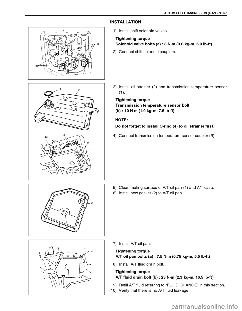
INSTALLATION
1) Install shift solenoid valves.
Tightening torque
Solenoid valve bolts (a) : 8 N·m (0.8 kg-m, 6.0 lb-ft)
2) Connect shift solenoid couplers.
3) Install oil strainer (2) and transmission temperature sensor
(1).
Tightening torque
Transmission temperature sensor bolt
(b) : 10 N·m (1.0 kg-m, 7.5 lb-ft)
4) Connect transmission temperature sensor coupler (3).
5) Clean mating surface of A/T oil pan (1) and A/T case.
6) Install new gasket (2) to A/T oil pan.
7) Install A/T oil pan.
Tightening torque
A/T oil pan bolts (a) : 7.5 N·m (0.75 kg-m, 5.5 lb-ft)
8) Install A/T fluid drain bolt.
Tightening torque
A/T fluid drain bolt (b) : 23 N·m (2.3 kg-m, 16.5 lb-ft)
9) Refill A/T fluid referring to “FLUID CHANGE” in this section.
10) Verify that there is no A/T fluid leakage.
NOTE:
Do not forget to install O-ring (4) to oil strainer first.
Page 178 of 447
7B-136 AUTOMATIC TRANSMISSION (4 A/T)
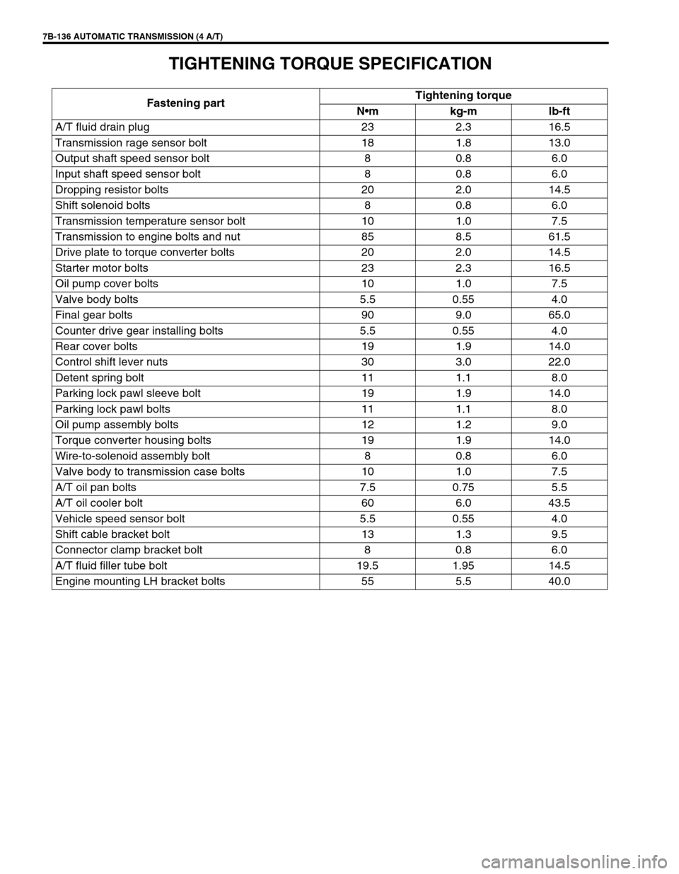
TIGHTENING TORQUE SPECIFICATION
Fastening partTightening torque
Nm kg-m lb-ft
A/T fluid drain plug 23 2.3 16.5
Transmission rage sensor bolt 18 1.8 13.0
Output shaft speed sensor bolt 8 0.8 6.0
Input shaft speed sensor bolt 8 0.8 6.0
Dropping resistor bolts 20 2.0 14.5
Shift solenoid bolts 8 0.8 6.0
Transmission temperature sensor bolt 10 1.0 7.5
Transmission to engine bolts and nut 85 8.5 61.5
Drive plate to torque converter bolts 20 2.0 14.5
Starter motor bolts 23 2.3 16.5
Oil pump cover bolts 10 1.0 7.5
Valve body bolts 5.5 0.55 4.0
Final gear bolts 90 9.0 65.0
Counter drive gear installing bolts 5.5 0.55 4.0
Rear cover bolts 19 1.9 14.0
Control shift lever nuts 30 3.0 22.0
Detent spring bolt 11 1.1 8.0
Parking lock pawl sleeve bolt 19 1.9 14.0
Parking lock pawl bolts 11 1.1 8.0
Oil pump assembly bolts 12 1.2 9.0
Torque converter housing bolts 19 1.9 14.0
Wire-to-solenoid assembly bolt 8 0.8 6.0
Valve body to transmission case bolts 10 1.0 7.5
A/T oil pan bolts 7.5 0.75 5.5
A/T oil cooler bolt 60 6.0 43.5
Vehicle speed sensor bolt 5.5 0.55 4.0
Shift cable bracket bolt 13 1.3 9.5
Connector clamp bracket bolt 8 0.8 6.0
A/T fluid filler tube bolt 19.5 1.95 14.5
Engine mounting LH bracket bolts 55 5.5 40.0
Page 203 of 447
TRANSFER 7D-5
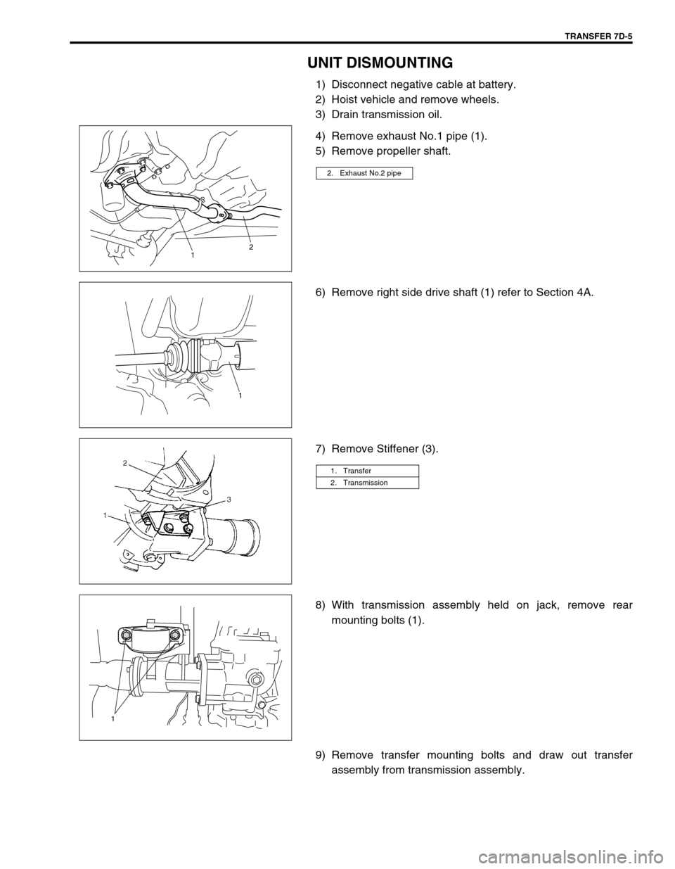
UNIT DISMOUNTING
1) Disconnect negative cable at battery.
2) Hoist vehicle and remove wheels.
3) Drain transmission oil.
4) Remove exhaust No.1 pipe (1).
5) Remove propeller shaft.
6) Remove right side drive shaft (1) refer to Section 4A.
7) Remove Stiffener (3).
8) With transmission assembly held on jack, remove rear
mounting bolts (1).
9) Remove transfer mounting bolts and draw out transfer
assembly from transmission assembly.
2. Exhaust No.2 pipe
12
1
1. Transfer
2. Transmission
1
Page 220 of 447
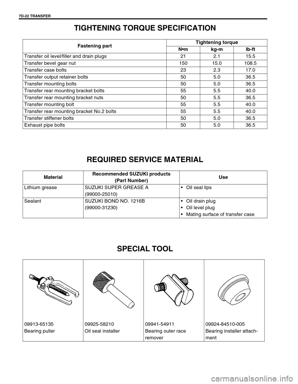
7D-22 TRANSFER
TIGHTENING TORQUE SPECIFICATION
REQUIRED SERVICE MATERIAL
SPECIAL TOOL
Fastening partTightening torque
Nm kg-m lb-ft
Transfer oil level/filler and drain plugs 21 2.1 15.5
Transfer bevel gear nut 150 15.0 108.5
Transfer case bolts 23 2.3 17.0
Transfer output retainer bolts 50 5.0 36.5
Transfer mounting bolts 50 5.0 36.5
Transfer rear mounting bracket bolts 55 5.5 40.0
Transfer rear mounting bracket nuts 50 5.5 36.5
Transfer mounting bolt 55 5.5 40.0
Transfer rear mounting bracket No.2 bolts 55 5.5 40.0
Transfer stiffener bolts 50 5.0 36.5
Exhaust pipe bolts 50 5.0 36.5
MaterialRecommended SUZUKI products
(Part Number)Use
Lithium grease SUZUKI SUPER GREASE A
(99000-25010)Oil seal lips
Sealant SUZUKI BOND NO. 1216B
(99000-31230)Oil drain plug
Oil level plug
Mating surface of transfer case
09913-65135 09925-58210 09941-54911 09924-84510-005
Bearing puller Oil seal installer Bearing outer race
removerBearing installer attach-
ment
Page 228 of 447
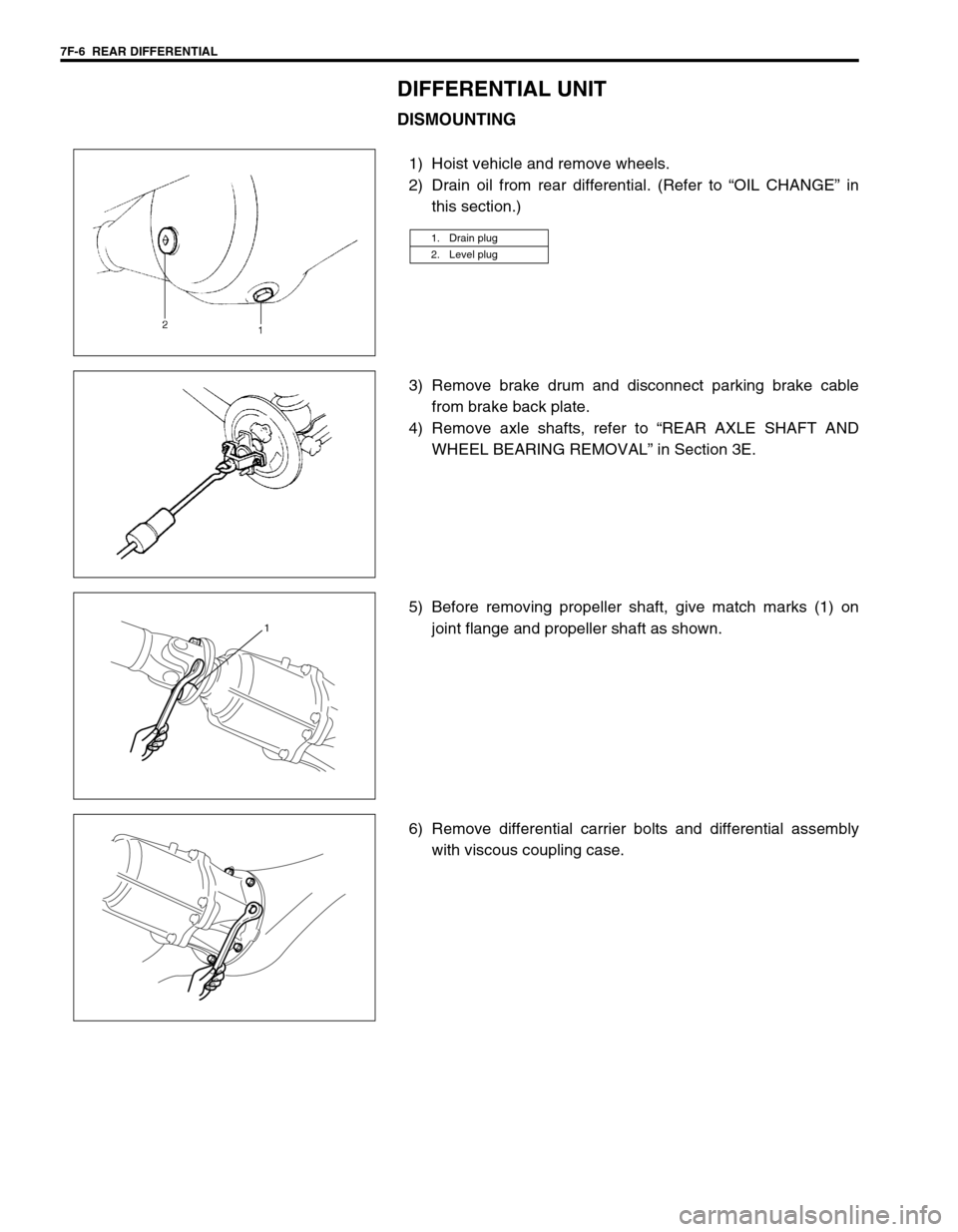
7F-6 REAR DIFFERENTIAL
DIFFERENTIAL UNIT
DISMOUNTING
1) Hoist vehicle and remove wheels.
2) Drain oil from rear differential. (Refer to “OIL CHANGE” in
this section.)
3) Remove brake drum and disconnect parking brake cable
from brake back plate.
4) Remove axle shafts, refer to “REAR AXLE SHAFT AND
WHEEL BEARING REMOVAL” in Section 3E.
5) Before removing propeller shaft, give match marks (1) on
joint flange and propeller shaft as shown.
6) Remove differential carrier bolts and differential assembly
with viscous coupling case.
1. Drain plug
2. Level plug
1