wheel torque SUZUKI SWIFT 2000 1.G Transmission Service Workshop Manual
[x] Cancel search | Manufacturer: SUZUKI, Model Year: 2000, Model line: SWIFT, Model: SUZUKI SWIFT 2000 1.GPages: 447, PDF Size: 10.54 MB
Page 2 of 447
7A-2 MANUAL TRANSMISSION
GENERAL DESCRIPTION
CONSTRUCTION AND SERVICING
The transmission provides five forward speeds and one reverse speed by means of three synchronizers and
three shafts-input shaft, countershaft and reverse gear shaft. All forward gears are in constant mesh, and
reverse uses a sliding idler gear arrangement.
The low speed synchronizer is mounted on counter shaft and engaged with counter shaft first gear or second
gear, while the high speed synchronizer is done on input shaft and engaged with input shaft third gear or fourth
gear.
The fifth speed synchronizer on input shaft is engaged with input shaft fifth gear mounted on the input shaft.
The double cone synchronizing mechanism is provided to 2nd gear synchromesh device for high performance
of shifting to 2nd gear.
The countershaft turns the final gear and differential assembly, thereby turning the front drive shafts which are
attached to the front wheels.
4WD model is equipped with transfer assembly on transmission being mated to right side of differential output in
transmission.
For servicing, it is necessary to use genuine sealant or its equivalent on mating surfaces of transmission case
which is made of aluminum. The case fastening bolts must be tightened to specified torque by means of torque
wrench. It is also important that all parts are thoroughly cleaned with cleaning fluid and air dried before reas-
sembling.
Further, care must be taken to adjust preload of counter shaft taper roller bearings. New synchronizer rings are
prohibited from being lapped with respective gear cones by using lapping compound before they are assembled.
Page 6 of 447
7A-6 MANUAL TRANSMISSION
OIL CHANGE
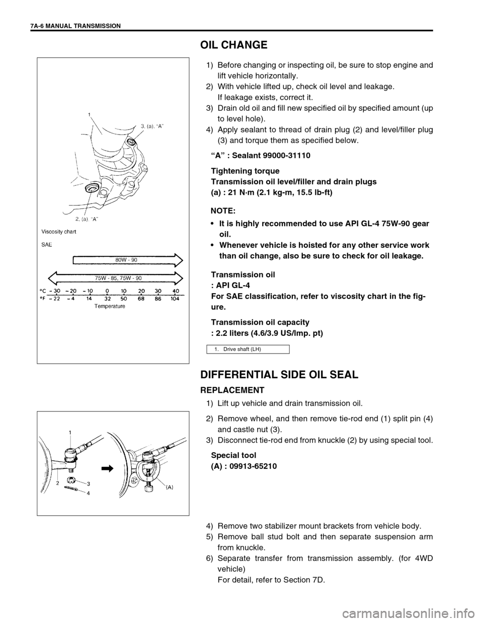
1) Before changing or inspecting oil, be sure to stop engine and
lift vehicle horizontally.
2) With vehicle lifted up, check oil level and leakage.
If leakage exists, correct it.
3) Drain old oil and fill new specified oil by specified amount (up
to level hole).
4) Apply sealant to thread of drain plug (2) and level/filler plug
(3) and torque them as specified below.
“A” : Sealant 99000-31110
Tightening torque
Transmission oil level/filler and drain plugs
(a) : 21 N·m (2.1 kg-m, 15.5 lb-ft)
Transmission oil
: API GL-4
For SAE classification, refer to viscosity chart in the fig-
ure.
Transmission oil capacity
: 2.2 liters (4.6/3.9 US/lmp. pt)
DIFFERENTIAL SIDE OIL SEAL
REPLACEMENT
1) Lift up vehicle and drain transmission oil.
2) Remove wheel, and then remove tie-rod end (1) split pin (4)
and castle nut (3).
3) Disconnect tie-rod end from knuckle (2) by using special tool.
Special tool
(A) : 09913-65210
4) Remove two stabilizer mount brackets from vehicle body.
5) Remove ball stud bolt and then separate suspension arm
from knuckle.
6) Separate transfer from transmission assembly. (for 4WD
vehicle)
For detail, refer to Section 7D. NOTE:
It is highly recommended to use API GL-4 75W-90 gear
oil.
Whenever vehicle is hoisted for any other service work
than oil change, also be sure to check for oil leakage.
1. Drive shaft (LH)
Page 62 of 447
7B-20 AUTOMATIC TRANSMISSION (4 A/T)
STALL TEST
This test is to check overall performance of automatic transmis-
sion and engine by measuring stall speed at “D” and “R” ranges.
Be sure to perform this test only when transmission fluid is at nor-
mal operating temperature and its level is between FULL and
LOW marks.
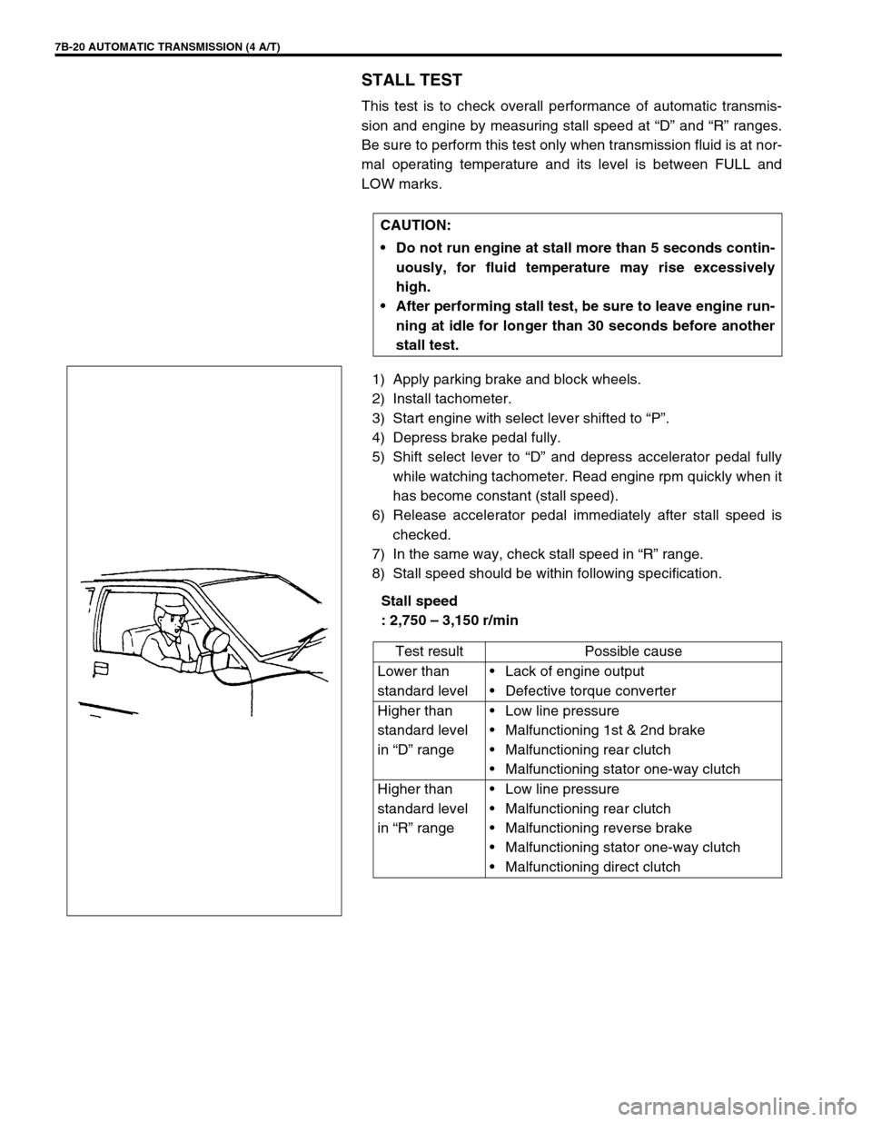
1) Apply parking brake and block wheels.
2) Install tachometer.
3) Start engine with select lever shifted to “P”.
4) Depress brake pedal fully.
5) Shift select lever to “D” and depress accelerator pedal fully
while watching tachometer. Read engine rpm quickly when it
has become constant (stall speed).
6) Release accelerator pedal immediately after stall speed is
checked.
7) In the same way, check stall speed in “R” range.
8) Stall speed should be within following specification.
Stall speed
: 2,750 – 3,150 r/min CAUTION:
Do not run engine at stall more than 5 seconds contin-
uously, for fluid temperature may rise excessively
high.
After performing stall test, be sure to leave engine run-
ning at idle for longer than 30 seconds before another
stall test.
Test result Possible cause
Lower than
standard levelLack of engine output
Defective torque converter
Higher than
standard level
in “D” rangeLow line pressure
Malfunctioning 1st & 2nd brake
Malfunctioning rear clutch
Malfunctioning stator one-way clutch
Higher than
standard level
in “R” rangeLow line pressure
Malfunctioning rear clutch
Malfunctioning reverse brake
Malfunctioning stator one-way clutch
Malfunctioning direct clutch
Page 183 of 447

CLUTCH 7C-1
6F1
6F2
6G
6H
6K
7A1
7B1
7C1
7D
7E
7C
8A
8B
8C
8D
8E
9
10
10A
10B
SECTION 7C
CLUTCH
CONTENTS
GENERAL DESCRIPTION .............................. 7C-2
DIAGNOSIS ..................................................... 7C-3
ON-VEHICLE SERVICE .................................. 7C-4
CLUTCH CABLE .......................................... 7C-4
CLUTCH PEDAL AND CLUTCH PEDAL
BRACKET .................................................... 7C-6
CLUTCH PEDAL HEIGHT ....................... 7C-7
CLUTCH PEDAL FREE TRAVEL ............ 7C-7UNIT REPAIR OVERHAUL ............................. 7C-8
CLUTCH COVER, CLUTCH DISC AND
FLYWHEEL.................................................. 7C-8
CLUTCH RELEASE SYSTEM ................... 7C-11
TIGHTENING TORQUE SPECIFICATION.... 7C-14
REQUIRED SERVICE MATERIAL................ 7C-14
SPECIAL TOOL ............................................ 7C-14
WARNING:
For vehicles equipped with Supplemental Restraint (Air Bag) System:
Service on and around the air bag system components or wiring must be performed only by an
authorized SUZUKI dealer. Refer to “Air Bag System Components and Wiring Location View” under
“General Description” in air bag system section in order to confirm whether you are performing ser-
vice on or near the air bag system components or wiring. Please observe all WARNINGS and “Ser-
vice Precautions” under “On-Vehicle Service” in air bag system section before performing service
on or around the air bag system components or wiring. Failure to follow WARNINGS could result in
unintentional activation of the system or could render the system inoperative. Either of these two
conditions may result in severe injury.
Technical service work must be started at least 90 seconds after the ignition switch is turned to the
“LOCK” position and the negative cable is disconnected from the battery. Otherwise, the system
may be activated by reserve energy in the Sensing and Diagnostic Module (SDM).
Page 190 of 447
7C-8 CLUTCH
UNIT REPAIR OVERHAUL
CLUTCH COVER, CLUTCH DISC AND FLYWHEEL
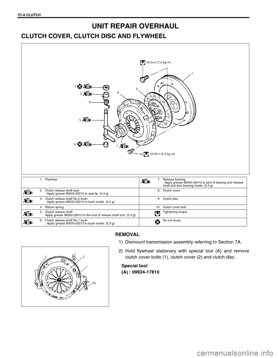
REMOVAL
1) Dismount transmission assembly referring to Section 7A.
2) Hold flywheel stationary with special tool (A) and remove
clutch cover bolts (1), clutch cover (2) and clutch disc.
Special tool
(A) : 09924-17810
1. Flywheel7. Release bearing
: Apply grease 99000-25010 to joint of bearing and release
shaft and also bearing inside. (0.3 g)
2. Clutch release shaft seal
: Apply grease 99000-25010 to seal lip. (0.3 g)8. Clutch cover
3. Clutch release shaft No.2 bush
: Apply grease 99000-25010 to bush inside. (0.3 g)9. Clutch disc
4. Return spring 10. Clutch cover bolt
5. Clutch release shaft
Apply grease 99000-25010 to the end of release shaft arm. (0.3 g)Tightening torque
6. Clutch release shaft No.1 bush
: Apply grease 99000-25010 to bush inside. (0.3 g)Do not reuse.
Page 192 of 447
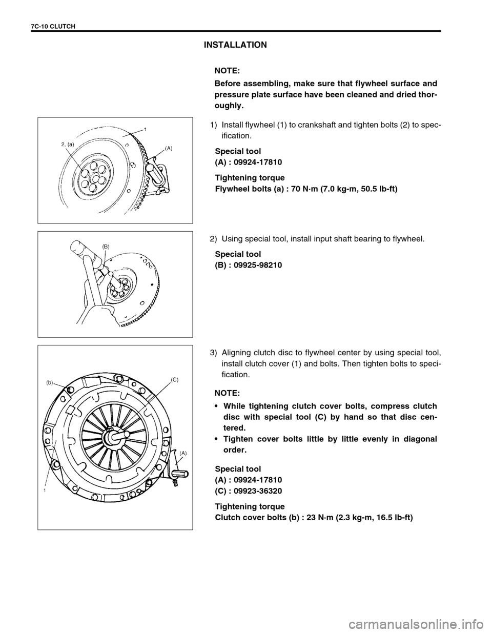
7C-10 CLUTCH
INSTALLATION
1) Install flywheel (1) to crankshaft and tighten bolts (2) to spec-
ification.
Special tool
(A) : 09924-17810
Tightening torque
Flywheel bolts (a) : 70 N·m (7.0 kg-m, 50.5 lb-ft)
2) Using special tool, install input shaft bearing to flywheel.
Special tool
(B) : 09925-98210
3) Aligning clutch disc to flywheel center by using special tool,
install clutch cover (1) and bolts. Then tighten bolts to speci-
fication.
Special tool
(A) : 09924-17810
(C) : 09923-36320
Tightening torque
Clutch cover bolts (b) : 23 N·m (2.3 kg-m, 16.5 lb-ft) NOTE:
Before assembling, make sure that flywheel surface and
pressure plate surface have been cleaned and dried thor-
oughly.
NOTE:
While tightening clutch cover bolts, compress clutch
disc with special tool (C) by hand so that disc cen-
tered.
Tighten cover bolts little by little evenly in diagonal
order.
Page 196 of 447
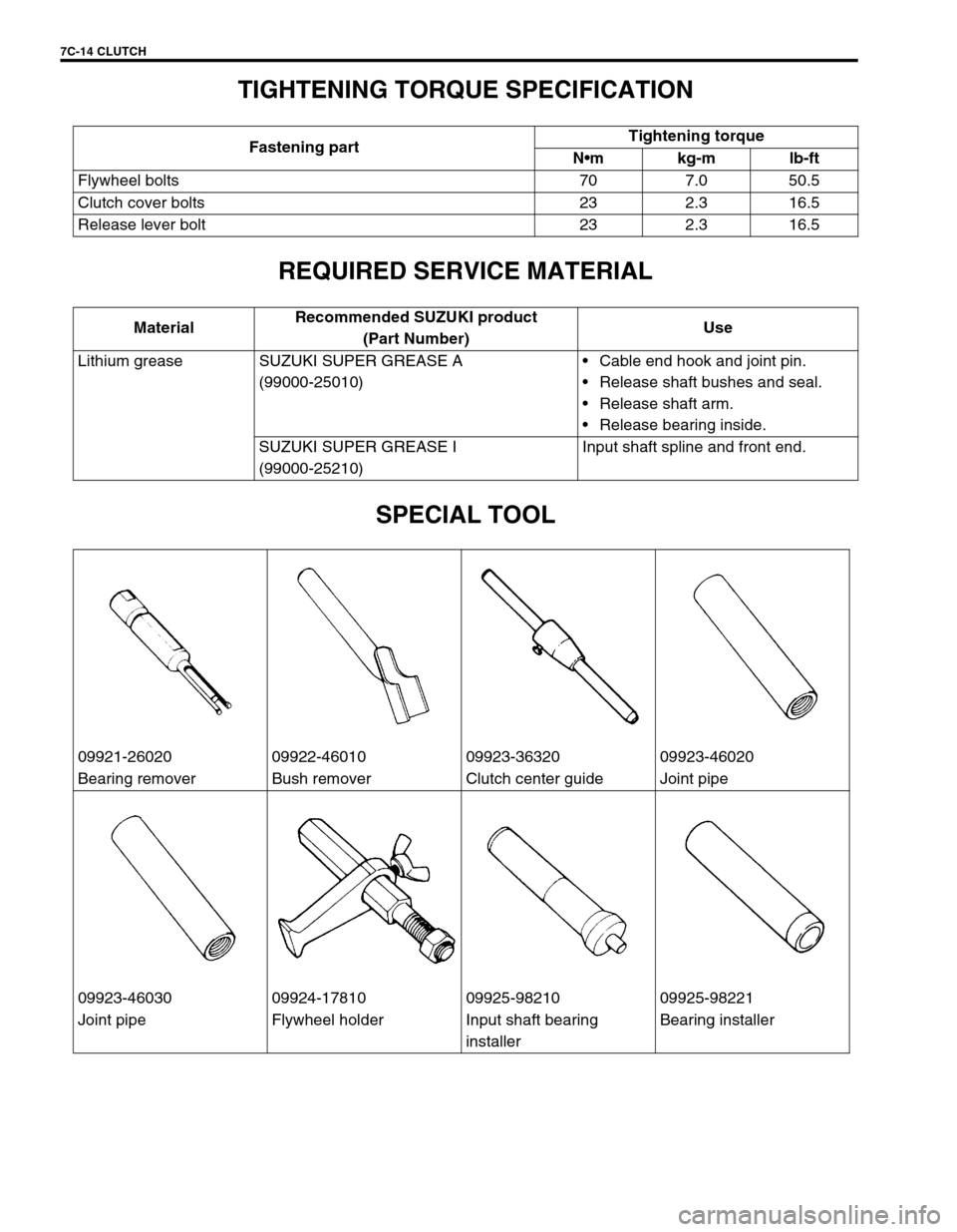
7C-14 CLUTCH
TIGHTENING TORQUE SPECIFICATION
REQUIRED SERVICE MATERIAL
SPECIAL TOOL
Fastening partTightening torque
Nm kg-m lb-ft
Flywheel bolts 70 7.0 50.5
Clutch cover bolts 23 2.3 16.5
Release lever bolt 23 2.3 16.5
MaterialRecommended SUZUKI product
(Part Number)Use
Lithium grease SUZUKI SUPER GREASE A
(99000-25010)Cable end hook and joint pin.
Release shaft bushes and seal.
Release shaft arm.
Release bearing inside.
SUZUKI SUPER GREASE I
(99000-25210)Input shaft spline and front end.
09921-26020 09922-46010 09923-36320 09923-46020
Bearing remover Bush remover Clutch center guide Joint pipe
09923-46030 09924-17810 09925-98210 09925-98221
Joint pipe Flywheel holder Input shaft bearing
installerBearing installer
Page 224 of 447
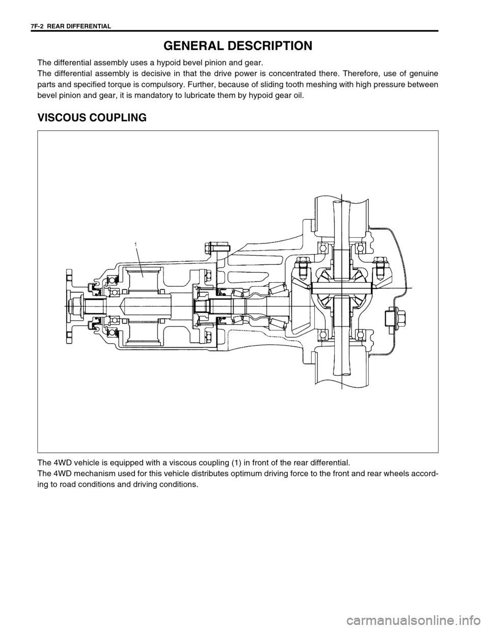
7F-2 REAR DIFFERENTIAL
GENERAL DESCRIPTION
The differential assembly uses a hypoid bevel pinion and gear.
The differential assembly is decisive in that the drive power is concentrated there. Therefore, use of genuine
parts and specified torque is compulsory. Further, because of sliding tooth meshing with high pressure between
bevel pinion and gear, it is mandatory to lubricate them by hypoid gear oil.
VISCOUS COUPLING
The 4WD vehicle is equipped with a viscous coupling (1) in front of the rear differential.
The 4WD mechanism used for this vehicle distributes optimum driving force to the front and rear wheels accord-
ing to road conditions and driving conditions.
Page 229 of 447
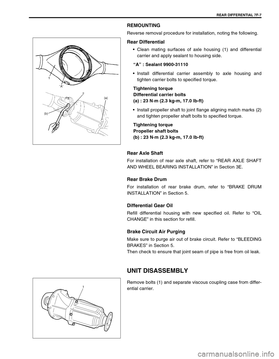
REAR DIFFERENTIAL 7F-7
REMOUNTING
Reverse removal procedure for installation, noting the following.
Rear Differential
Clean mating surfaces of axle housing (1) and differential
carrier and apply sealant to housing side.
“A” : Sealant 9900-31110
Install differential carrier assembly to axle housing and
tighten carrier bolts to specified torque.
Tightening torque
Differential carrier bolts
(a) : 23 N·m (2.3 kg-m, 17.0 lb-ft)
Install propeller shaft to joint flange aligning match marks (2)
and tighten propeller shaft bolts to specified torque.
Tightening torque
Propeller shaft bolts
(b) : 23 N·m (2.3 kg-m, 17.0 lb-ft)
Rear Axle Shaft
For installation of rear axle shaft, refer to “REAR AXLE SHAFT
AND WHEEL BEARING INSTALLATION” in Section 3E.
Rear Brake Drum
For installation of rear brake drum, refer to “BRAKE DRUM
INSTALLATION” in Section 5.
Differential Gear Oil
Refill differential housing with new specified oil. Refer to “OIL
CHANGE” in this section for refill.
Brake Circuit Air Purging
Make sure to purge air out of brake circuit. Refer to “BLEEDING
BRAKES” in Section 5.
Then check to ensure that joint seam of pipe is free from oil leak.
UNIT DISASSEMBLY
Remove bolts (1) and separate viscous coupling case from differ-
ential carrier.1