ECU SUZUKI SWIFT 2004 2.G Service Service Manual
[x] Cancel search | Manufacturer: SUZUKI, Model Year: 2004, Model line: SWIFT, Model: SUZUKI SWIFT 2004 2.GPages: 1496, PDF Size: 34.44 MB
Page 399 of 1496
Downloaded from www.Manualslib.com manuals search engine Ignition System: 1H-7
High-Tension Cord InspectionS7RS0B1806002
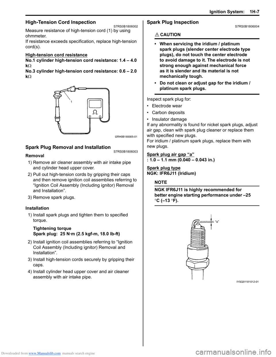
Measure resistance of high-tension cord (1) by using
ohmmeter.
If resistance exceeds specification, replace high-tension
cord(s).
High-tension cord resistance
No.1 cylinder high-tension cord resistance: 1.4 – 4.0
k Ω
No.3 cylinder high-tension cord resistance: 0.6 – 2.0
k Ω
Spark Plug Removal and InstallationS7RS0B1806003
Removal
1) Remove air cleaner assembly with air intake pipe and cylinder head upper cover.
2) Pull out high-tension cords by gripping their caps and then remove ignition coil assemblies referring to
“Ignition Coil Assembly (Inc luding ignitor) Removal
and Installation”.
3) Remove spark plugs.
Installation 1) Install spark plugs and tighten them to specified torque.
Tightening torque
Spark plug: 25 N·m (2.5 kgf-m, 18.0 lb-ft)
2) Install ignition coil assemblies referring to “Ignition Coil Assembly (Including ignitor) Removal and
Installation”.
3) Install high-tension cords securely by gripping their caps.
4) Install cylinder head upper cover and air cleaner assembly with air intake pipe.
Spark Plug InspectionS7RS0B1806004
CAUTION!
• When servicing the iridium / platinum
spark plugs (slender center electrode type
plugs), do not touch the center electrode
to avoid damage to it. The electrode is not
strong enough against mechanical force
as it is slender and its material is not
mechanically tough.
• Do not clean or adjust gap for the iridium / platinum spark plugs.
Inspect spark plug for:
• Electrode wear
• Carbon deposits
• Insulator damage
If any abnormality is found for nickel spark plugs, adjust
air gap, clean with spark plug cleaner or replace them
with specified new plugs.
For iridium / platinum spark plugs, replace them with
new plugs.
Spark plug air gap
“a”
: 1.0 – 1.1 mm (0.040 – 0.043 in.)
Spark plug type
NGK: IFR6J11 (Iridium)
NOTE
NGK IFR6J11 is highly recommended for
better engine starting performance under –25
°C (–13 °F).
I2RH0B180005-01
IYSQ01181012-01
Page 411 of 1496
Downloaded from www.Manualslib.com manuals search engine Charging System: 1J-1
Engine
Charging System
General Description
Battery DescriptionS7RS0B1A01001
The battery has three major functions in the electrical
system.
• It is a source of electrical energy for cranking the engine.
• It acts as a voltage stabilizer for the electrical system.
• It can, for a limited time, provide energy when the electrical load exceeds the output of the generator.
Carrier and Hold-Down
The battery carrier should be in good condition so that it
will support the battery securely and keep it level. Before
installing the battery, the ba ttery carrier and hold-down
clamp should be clean and free from corrosion and
make certain there are no parts in carrier.
To prevent the battery from shaking in its carrier, the
hold-down bolts should be tight enough but not over-
tightened.
Electrolyte Freezing
The freezing point of electrolyte depends on its specific
gravity. Since freezing may ruin a battery, it should be
protected against freezing by keeping it in a fully
charged condition. If a battery is frozen accidentally, it
should not be charged until it is warmed.
Sulfation
If the battery is allowed to stand for a long period in
discharged condition, the lead sulfate becomes
converted into a hard, cryst alline substance, which will
not easily turn back to the active material again during
the subsequent recharging. “Sulfation” means the result
as well as the process of that reaction. Such a battery
can be revived by very slow charging and may be
restored to usable condition but its capacity is lower than
before. Built-In Indicator (If Equipped)
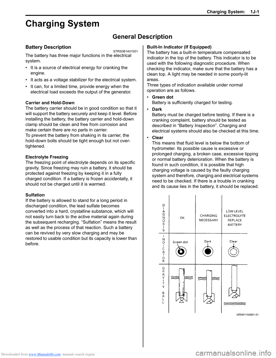
The battery has a built-in temperature compensated
indicator in the top of the battery. This indicator is to be
used with the following diagnostic procedure. When
checking the indicator, make sure that the battery has a
clean top. A light may be needed in some poorly-lit
areas.
Three types of indication available under normal
operation are as follows.
•
Green dot
Battery is sufficiently charged for testing.
• Dark
Battery must be charged before testing. If there is a
cranking complaint, battery should be tested as
described in “Battery Inspection”. Charging and
electrical systems should also be checked at this time.
• Clear
This means that fluid level is below the bottom of
hydrometer. Its possible cause is excessive or
prolonged charging, a broken case, excessive tipping
or normal battery deteriorat ion. When the battery is
found in such condition, it is possible that high
charging voltage is caused by the faulty charging
system and therefore, charging and electrical systems
need to be checked. If there is a trouble in cranking
and its cause lies in the battery, it should be replaced.
I2RH011A0001-01
Page 417 of 1496
Downloaded from www.Manualslib.com manuals search engine Charging System: 1J-7
With Charging Equipment
CAUTION!
When jump starting engine with charging
equipment, be sure equipment used is 12-
volt and negative ground. Do not use 24-volt
charging equipment. Using such equipment
can cause serious damage to electrical
system or electronic parts.
Battery Dismounting and RemountingS7RS0B1A06002
WARNING!
When handling battery, following safety
precautions should be followed:
• Hydrogen gas is produced by battery. A flame or spark near battery may cause the
gas to ignite.
• Battery fluid is highly acidic. Avoid spilling on clothing or other fabric. Any spilled
electrolyte should be flushed with large
quantity of water and cleaned immediately.
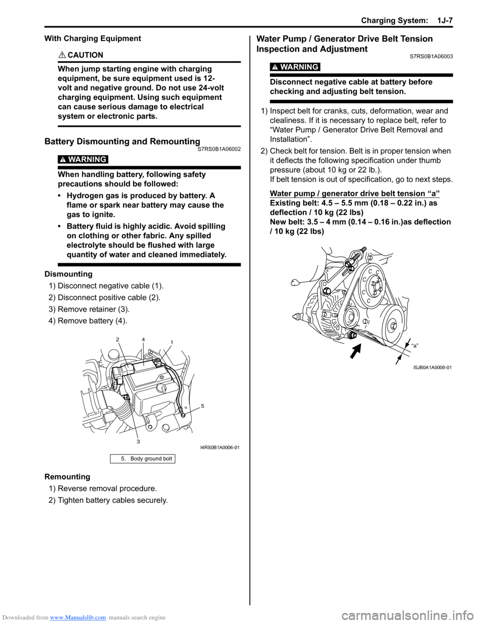
Dismounting
1) Disconnect negative cable (1).
2) Disconnect positive cable (2).
3) Remove retainer (3).
4) Remove battery (4).
Remounting 1) Reverse removal procedure.
2) Tighten battery cables securely.
Water Pump / Generator Drive Belt Tension
Inspection and Adjustment
S7RS0B1A06003
WARNING!
Disconnect negative cable at battery before
checking and adjusting belt tension.
1) Inspect belt for cranks, cuts, deformation, wear and clealiness. If it is necessary to replace belt, refer to
“Water Pump / Generator Drive Belt Removal and
Installation”.
2) Check belt for tension. Belt is in proper tension when it deflects the following specification under thumb
pressure (about 10 kg or 22 lb.).
If belt tension is out of spec ification, go to next steps.
Water pump / generator drive belt tension
“a”
Existing belt: 4.5 – 5.5 mm (0.18 – 0.22 in.) as
deflection / 10 kg (22 lbs)
New belt: 3.5 – 4 mm (0.14 – 0.16 in.)as deflection
/ 10 kg (22 lbs)
5. Body ground bolt
1
3 5
2
4
I4RS0B1A0006-01
“a”
I5JB0A1A0008-01
Page 427 of 1496
Downloaded from www.Manualslib.com manuals search engine Exhaust System: 1K-4
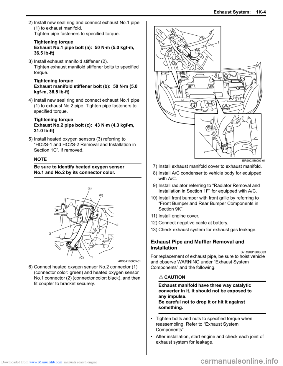
2) Install new seal ring and connect exhaust No.1 pipe (1) to exhaust manifold.
Tighten pipe fasteners to specified torque.
Tightening torque
Exhaust No.1 pipe bolt (a): 50 N·m (5.0 kgf-m,
36.5 lb-ft)
3) Install exhaust manifold stiffener (2). Tighten exhaust manifold stiffener bolts to specified
torque.
Tightening torque
Exhaust manifold stiffener bolt (b): 50 N·m (5.0
kgf-m, 36.5 lb-ft)
4) Install new seal ring and connect exhaust No.1 pipe (1) to exhaust No.2 pipe. Tighten pipe fasteners to
specified torque.
Tightening torque
Exhaust No.2 pipe bolt (c): 43 N·m (4.3 kgf-m,
31.0 lb-ft)
5) Install heated oxygen sensors (3) referring to “HO2S-1 and HO2S-2 Removal and Installation in
Section 1C”, if removed.
NOTE
Be sure to identify heated oxygen sensor
No.1 and No.2 by its connector color.
6) Connect heated oxygen sensor No.2 connector (1)
(connector color: green) and heated oxygen sensor
No.1 connector (2) (connector color: black), and then
fit coupler to br acket securely. 7) Install exhaust manifold cover to exhaust manifold.
8) Install A/C condenser to vehicle body for equipped
with A/C.
9) Install radiator referrin g to “Radiator Removal and
Installation in Section 1F” for equipped with A/C.
10) Install front bumper with fr ont grille by referring to
“Front Bumper and Rear Bumper Components in
Section 9K”.
11) Install engine cover.
12) Connect negative cable at battery.
13) Check exhaust system for exhaust gas leakage.
Exhaust Pipe and Muffler Removal and
Installation
S7RS0B1B06003
For replacement of exhaust pipe, be sure to hoist vehicle
and observe WARNING under “Exhaust System
Components” and the following.
CAUTION!
Exhaust manifold have three way catalytic
converter in it, it should not be exposed to
any impulse.
Be careful not to drop it or hit it against
something.
• Tighten bolts and nuts to specified torque when reassembling. Refer to “Exhaust System
Components”.
• After installation, start engine and check each joint of exhaust system for leakage.
2
(b)
(a)
1(C)
3
I4RS0A1B0005-01
1
2
I6RS0C1B0002-01
Page 469 of 1496
Downloaded from www.Manualslib.com manuals search engine Wheels and Tires: 2D-2
Lower than recommended pressure can cause:
• Tire squeal on turns
• Hard Steering
• Rapid and uneven wear on the edges of the tread
• Tire rim bruises and rupture
• Tire cord breakage
• High tire temperature
• Reduced handling
• High fuel consumption
Replacement Tires
When replacement is necessary, the original equipment
type tire should be used. Refer to the Tire Placard.
Replacement tires should be of the same size, load
range and construction as those originally on the vehicle.
Use of any other size or type tire may affect ride,
handling, speedometer / odometer calibration, vehicle
ground clearance and tire or snow chain clearance to the
body and chassis.
It is recommended that new tires be installed in pairs on
the same axle. If necessary to replace only one tire, it
should be paired with the tire having the most tread, to
equalize braking traction.
WARNING!
Do not mix different types of tires on the
same vehicle such as radial, bias and bias-
belted tires except in emergencies, because
handling may be seriously affected and may
result in loss of control.
The metric term for tire infl ation pressure is the kilo
pascal (kPa). Tire pressures is usually printed in both
kPa and kgf/cm
2 on the “Tire Placard”.
Metric tire gauges are available from tool suppliers.
The chart, shown the table, converts commonly used
inflation pressures from kPa to kgf/cm
2 and psi.
Wheels DescriptionS7RS0B2401002
Wheel Maintenance
Wheel repairs that use welding, heating, or peening are
not approved. All damaged wheels should be replaced.
Replacement Wheels
Wheels must be replaced if they are bent, dented, have
excessive lateral or radial runout, air leak through welds,
have elongated bolt holes, if lug wheel bolts won’t stay
tight, or if they are heavily rusted. Wheels with greater
runout than shown in the following may cause
objectional vibrations.
Replacement wheels must be equivalent to the original
equipment wheels in load capacity, diameter, rim with
offset and mounting configuration. A wheel of improper
size or type may affect wheel and bearing life, brake
cooling, speedometer / odometer calibration, vehicle
ground clearance and tire clearance to body and
chassis.
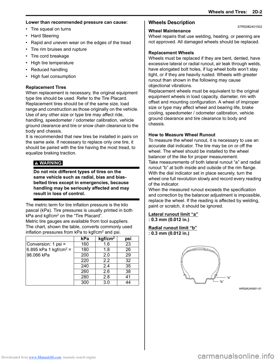
How to Measure Wheel Runout
To measure the wheel runout, it is necessary to use an
accurate dial indicator. The tire may be on or off the
wheel. The wheel should be installed to the wheel
balancer of the like for proper measurement.
Take measurements of both lateral runout “a” and radial
runout “b” at both inside an d outside of the rim flange.
With the dial indicator set in place securely, turn the
wheel one full revolution slowly and record every reading
of the indicator.
When the measured runout exceeds the specification
and correction by the balancer adjustment is impossible,
replace the wheel. If the reading is affected by welding,
paint or scratch, it should be ignored.
Lateral runout limit “a”
: 0.3 mm (0.012 in.)
Radial runout limit “b”
: 0.3 mm (0.012 in.)
kPa kgf/cm2psi
Conversion: 1 psi =
6.895 kPa 1 kgf/cm
2 =
98.066 kPa 160 1.6 23
180 1.8 26
200 2.0 29
220 2.2 32
240 2.4 35
260 2.6 38
280 2.8 41
300 3.0 44
I4RS0A240001-01
Page 479 of 1496
Downloaded from www.Manualslib.com manuals search engine Drive Shaft / Axle: 3A-1
Driveline / Axle
Drive Shaft / Axle
General Description
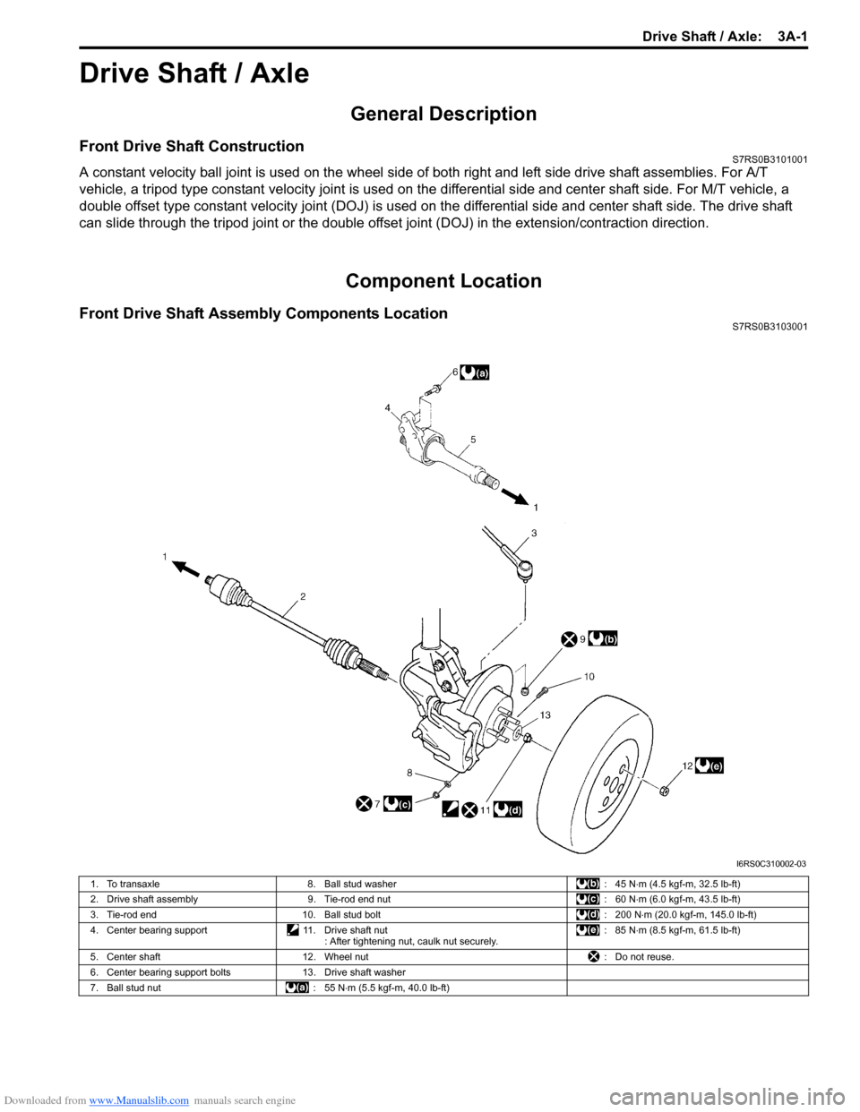
Front Drive Shaft ConstructionS7RS0B3101001
A constant velocity ball joint is used on the wheel side of both right and left side drive shaft assemblies. For A/T
vehicle, a tripod type constant velocity joint is used on the differential side and center shaft side. For M/T vehicle, a
double offset type constant velocity joint (DOJ) is used on the differential side and center shaft side. The drive shaft
can slide through the tripod joint or the double offset joint (DOJ) in the extension/contraction direction.
Component Location
Front Drive Shaft Assembly Components LocationS7RS0B3103001
I6RS0C310002-03
1. To transaxle 8. Ball stud washer : 45 N⋅m (4.5 kgf-m, 32.5 lb-ft)
2. Drive shaft assembly 9. Tie-rod end nut : 60 N⋅m (6.0 kgf-m, 43.5 lb-ft)
3. Tie-rod end 10. Ball stud bolt : 200 N⋅m (20.0 kgf-m, 145.0 lb-ft)
4. Center bearing support 11. Drive shaft nut
: After tightening nut, caulk nut securely. : 85 N
⋅m (8.5 kgf-m, 61.5 lb-ft)
5. Center shaft 12. Wheel nut : Do not reuse.
6. Center bearing support bolts 13. Drive shaft washer
7. Ball stud nut : 55 N⋅m (5.5 kgf-m, 40.0 lb-ft)
Page 487 of 1496
Downloaded from www.Manualslib.com manuals search engine Drive Shaft / Axle: 3A-9
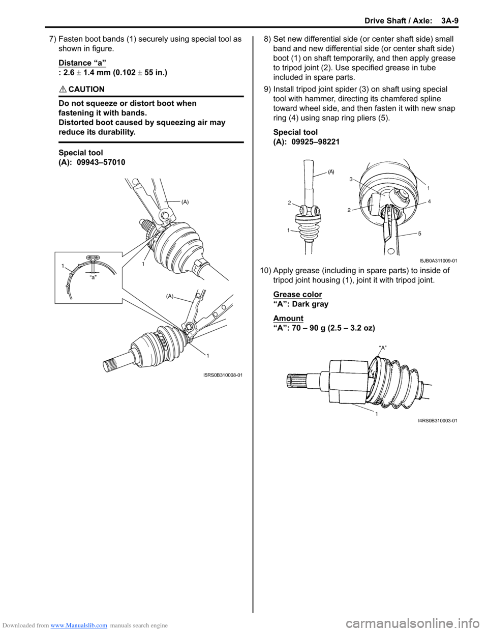
7) Fasten boot bands (1) securely using special tool as
shown in figure.
Distance “a”
: 2.6 ± 1.4 mm (0.102 ± 55 in.)
CAUTION!
Do not squeeze or distort boot when
fastening it with bands.
Distorted boot caused by squeezing air may
reduce its durability.
Special tool
(A): 09943–57010 8) Set new differential side (or center shaft side) small
band and new differential side (or center shaft side)
boot (1) on shaft temporarily, and then apply grease
to tripod joint (2). Use specified grease in tube
included in spare parts.
9) Install tripod joint spider (3) on shaft using special
tool with hammer, directing its chamfered spline
toward wheel side, and then fasten it with new snap
ring (4) using snap ring pliers (5).
Special tool
(A): 09925–98221
10) Apply grease (including in spare parts) to inside of tripod joint housing (1), jo int it with tripod joint.
Grease color
“A”: Dark gray
Amount
“A”: 70 – 90 g (2.5 – 3.2 oz)
(A)
1
(A)
1
“a”
1
I5RS0B310008-01
I5JB0A311009-01
I4RS0B310003-01
Page 492 of 1496
Downloaded from www.Manualslib.com manuals search engine 3A-14 Drive Shaft / Axle:
Center Shaft and Center Bearing Support
Disassembly and Reassembly
S7RS0B3106005
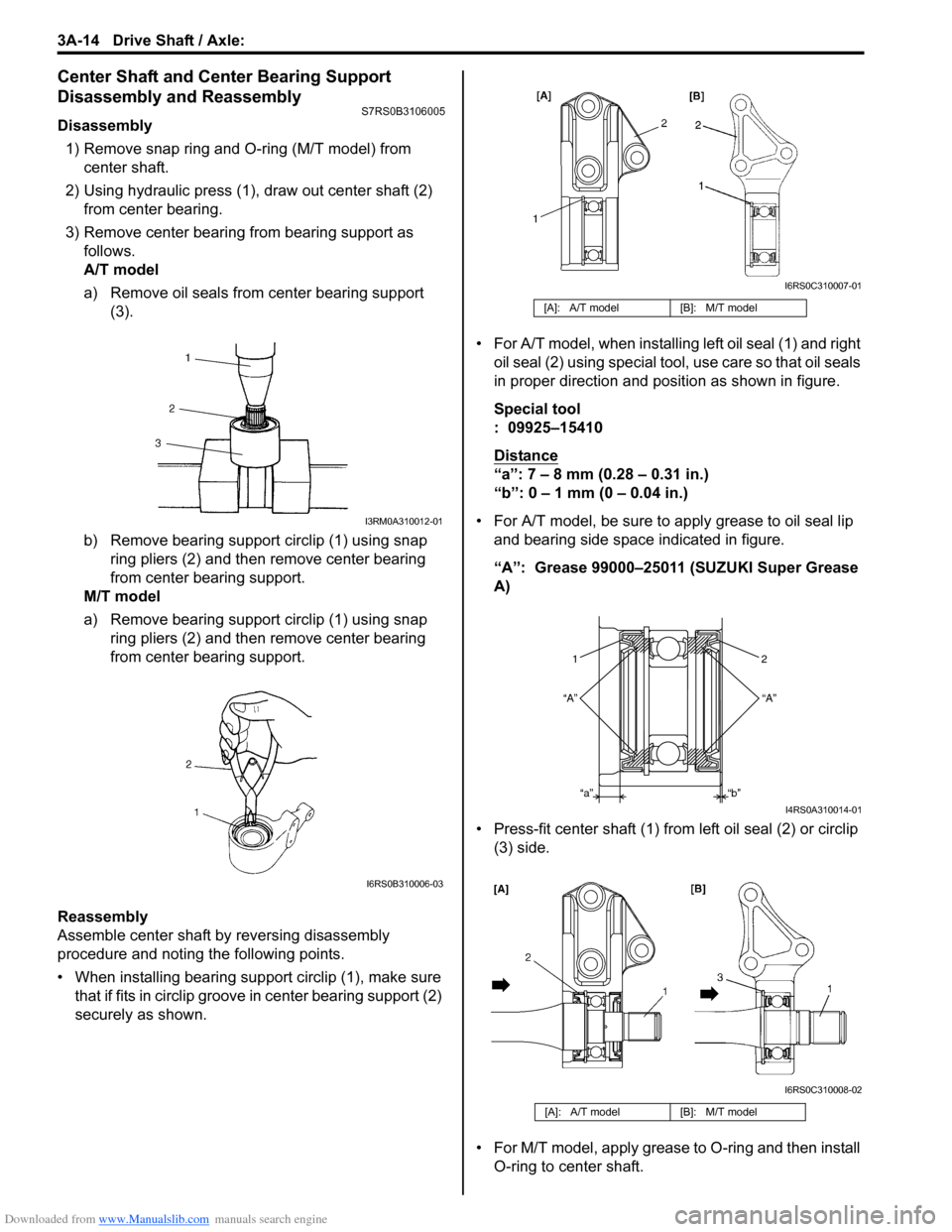
Disassembly1) Remove snap ring and O-ring (M/T model) from center shaft.
2) Using hydraulic press (1), draw out center shaft (2) from center bearing.
3) Remove center bearing from bearing support as follows.
A/T model
a) Remove oil seals from center bearing support (3).
b) Remove bearing support circlip (1) using snap ring pliers (2) and then remove center bearing
from center bearing support.
M/T model
a) Remove bearing support circlip (1) using snap ring pliers (2) and then remove center bearing
from center bearing support.
Reassembly
Assemble center shaft by reversing disassembly
procedure and noting the following points.
• When installing bearing support circlip (1), make sure
that if fits in circlip groove in center bearing support (2)
securely as shown. • For A/T model, when installing
left oil seal (1) and right
oil seal (2) using special tool, use care so that oil seals
in proper direction and position as shown in figure.
Special tool
: 09925–15410
Distance
“a”: 7 – 8 mm (0.28 – 0.31 in.)
“b”: 0 – 1 mm (0 – 0.04 in.)
• For A/T model, be sure to apply grease to oil seal lip and bearing side space indicated in figure.
“A”: Grease 99000–25011 (SUZUKI Super Grease
A)
• Press-fit center shaft (1) from left oil seal (2) or circlip
(3) side.
• For M/T model, apply grease to O-ring and then install O-ring to center shaft.
I3RM0A310012-01
I6RS0B310006-03
[A]: A/T model [B]: M/T model
[A]: A/T model [B]: M/T model
I6RS0C310007-01
12
“A” “A”
“a” “b”
I4RS0A310014-01
I6RS0C310008-02
Page 504 of 1496
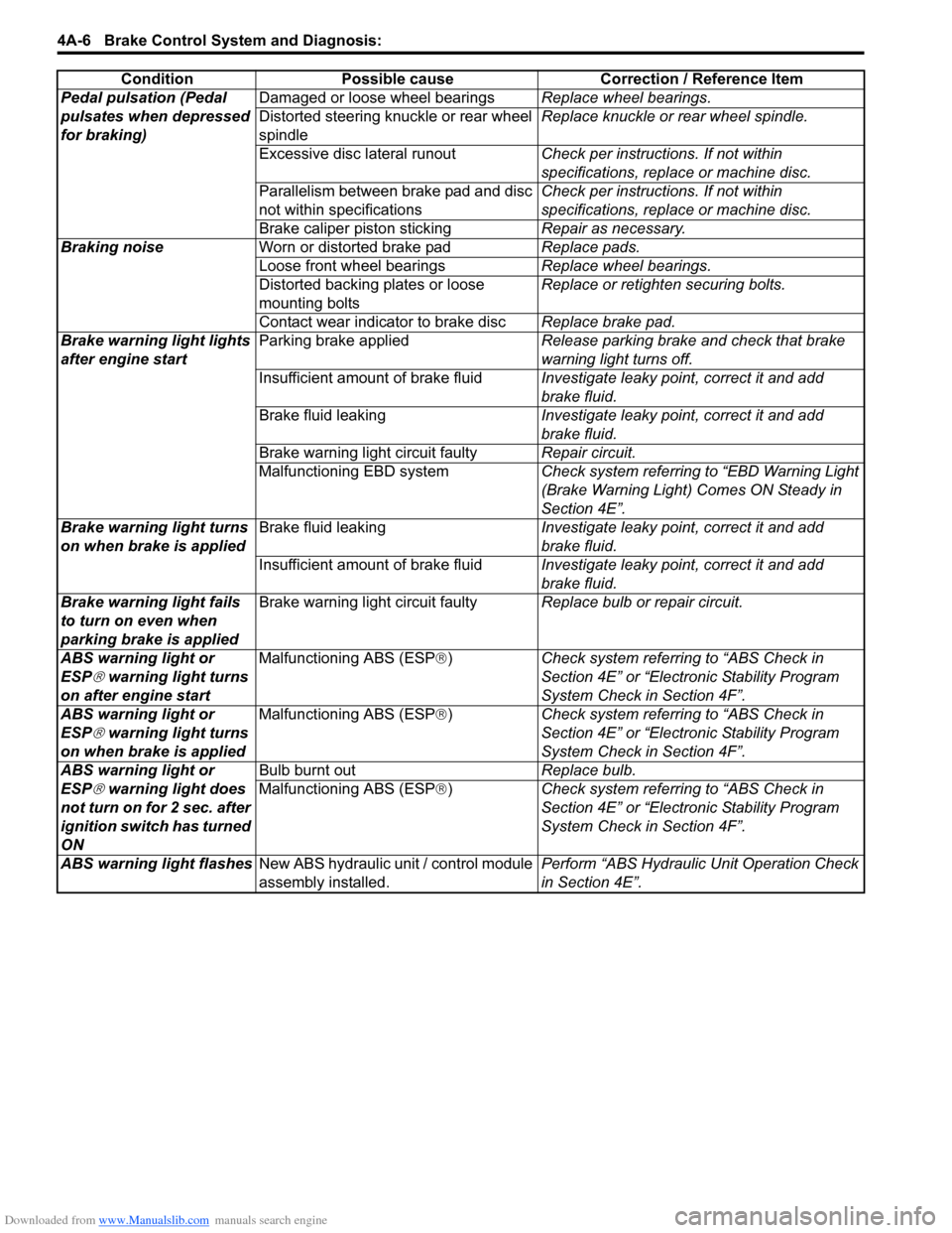
Downloaded from www.Manualslib.com manuals search engine 4A-6 Brake Control System and Diagnosis:
Pedal pulsation (Pedal
pulsates when depressed
for braking)Damaged or loose wheel bearings
Replace wheel bearings.
Distorted steering knuckle or rear wheel
spindle Replace knuckle or rear wheel spindle.
Excessive disc lateral runout Check per instructions. If not within
specifications, replace or machine disc.
Parallelism between brake pad and disc
not within specifications Check per instructions. If not within
specifications, replace or machine disc.
Brake caliper piston sticking Repair as necessary.
Braking noise Worn or distorted brake pad Replace pads.
Loose front wheel bearings Replace wheel bearings.
Distorted backing plates or loose
mounting bolts Replace or retighten securing bolts.
Contact wear indicator to brake disc Replace brake pad.
Brake warning light lights
after engine start Parking brake applied
Release parking brake and check that brake
warning light turns off.
Insufficient amount of brake fluid Investigate leaky point, correct it and add
brake fluid.
Brake fluid leaking Investigate leaky point, correct it and add
brake fluid.
Brake warning light circuit faulty Repair circuit.
Malfunctioning EBD system Check system referring to “EBD Warning Light
(Brake Warning Light) Comes ON Steady in
Section 4E”.
Brake warning light turns
on when brake is applied Brake fluid leaking
Investigate leaky point, correct it and add
brake fluid.
Insufficient amount of brake fluid Investigate leaky point, correct it and add
brake fluid.
Brake warning light fails
to turn on even when
parking brake is applied Brake warning light circuit faulty
Replace bulb or repair circuit.
ABS warning light or
ESP
® warning light turns
on after engine start Malfunctioning ABS (ESP
®) Check system referri ng to “ABS Check in
Section 4E” or “Electronic Stability Program
System Check in Section 4F”.
ABS warning light or
ESP
® warning light turns
on when brake is applied Malfunctioning ABS (ESP
®) Check system referri ng to “ABS Check in
Section 4E” or “Electronic Stability Program
System Check in Section 4F”.
ABS warning light or
ESP
® warning light does
not turn on for 2 sec. after
ignition switch has turned
ON Bulb burnt out
Replace bulb.
Malfunctioning ABS (ESP ®) Check system referri ng to “ABS Check in
Section 4E” or “Electronic Stability Program
System Check in Section 4F”.
ABS warning light flashes New ABS hydraulic unit / control module
assembly installed. Perform “ABS Hydraulic
Unit Operation Check
in Section 4E”.
Condition Possible cause Correction / Reference Item
Page 520 of 1496
Downloaded from www.Manualslib.com manuals search engine 4B-4 Front Brakes:
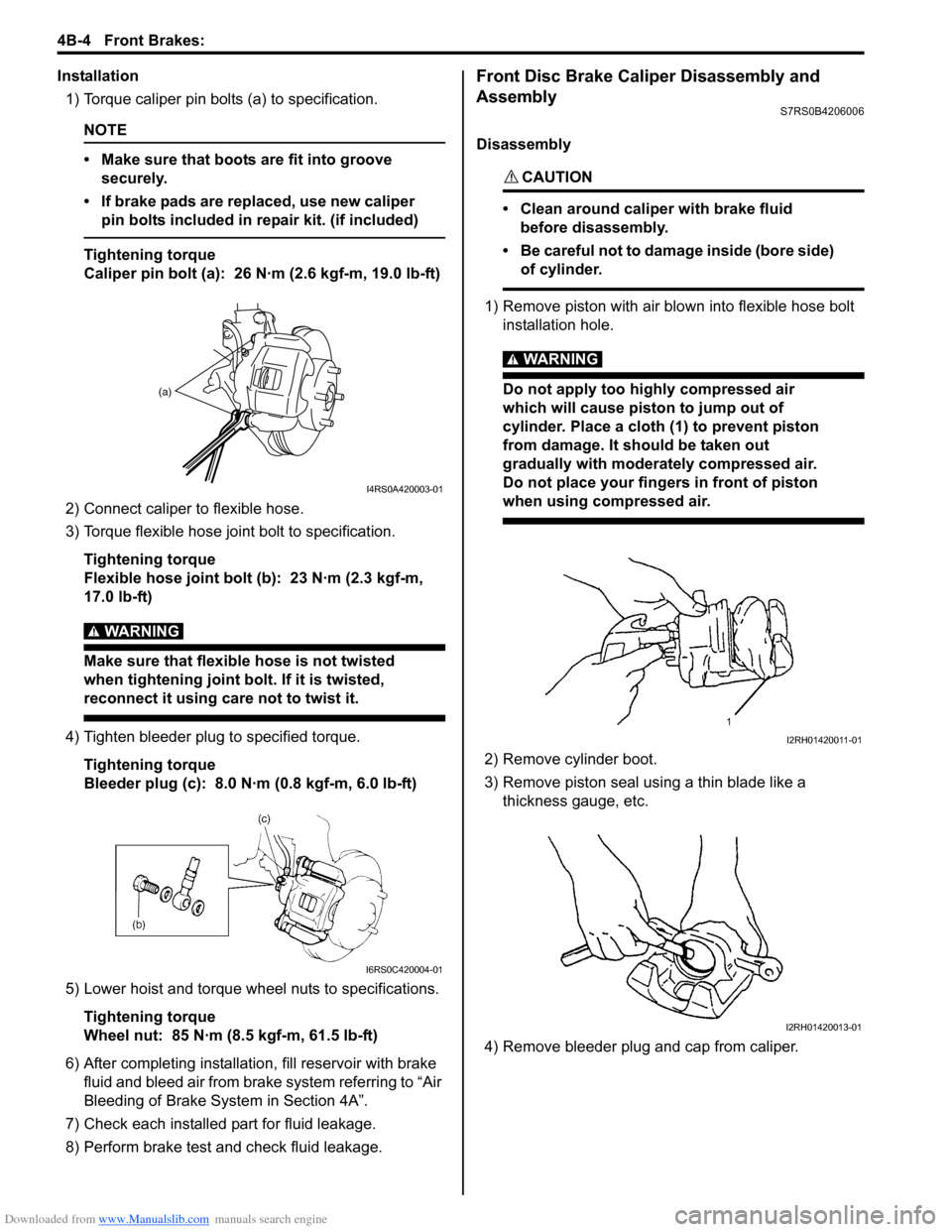
Installation1) Torque caliper pin bolts (a) to specification.
NOTE
• Make sure that boots are fit into groove securely.
• If brake pads are replaced, use new caliper pin bolts included in repair kit. (if included)
Tightening torque
Caliper pin bolt (a): 26 N·m (2.6 kgf-m, 19.0 lb-ft)
2) Connect caliper to flexible hose.
3) Torque flexible hose jo int bolt to specification.
Tightening torque
Flexible hose joint bolt (b): 23 N·m (2.3 kgf-m,
17.0 lb-ft)
WARNING!
Make sure that flexible hose is not twisted
when tightening joint bolt. If it is twisted,
reconnect it using care not to twist it.
4) Tighten bleeder plug to specified torque. Tightening torque
Bleeder plug (c): 8.0 N·m (0.8 kgf-m, 6.0 lb-ft)
5) Lower hoist and torque wheel nuts to specifications. Tightening torque
Wheel nut: 85 N·m (8.5 kgf-m, 61.5 lb-ft)
6) After completing installation, fill reservoir with brake
fluid and bleed air from brake system referring to “Air
Bleeding of Brake System in Section 4A”.
7) Check each installed part for fluid leakage.
8) Perform brake test and check fluid leakage.
Front Disc Brake Caliper Disassembly and
Assembly
S7RS0B4206006
Disassembly
CAUTION!
• Clean around caliper with brake fluid before disassembly.
• Be careful not to damage inside (bore side) of cylinder.
1) Remove piston with air blown into flexible hose bolt installation hole.
WARNING!
Do not apply too highly compressed air
which will cause piston to jump out of
cylinder. Place a cloth (1) to prevent piston
from damage. It should be taken out
gradually with moderately compressed air.
Do not place your fingers in front of piston
when using compressed air.
2) Remove cylinder boot.
3) Remove piston seal using a thin blade like a thickness gauge, etc.
4) Remove bleeder plug and cap from caliper.
(a)
I4RS0A420003-01
I6RS0C420004-01
I2RH01420011-01
I2RH01420013-01