ECU SUZUKI SWIFT 2004 2.G Service Manual Online
[x] Cancel search | Manufacturer: SUZUKI, Model Year: 2004, Model line: SWIFT, Model: SUZUKI SWIFT 2004 2.GPages: 1496, PDF Size: 34.44 MB
Page 876 of 1496
Downloaded from www.Manualslib.com manuals search engine 6B-5 Steering Wheel and Column:
Contact Coil Cable Assembly Removal and
Installation
S7RS0B6206003
CAUTION!
Do not turn contact coil more than allowable
number of turns (about two and a half turns
from the center position clockwise or
counterclockwise respectively), or coil will
break.
Removal
1) Disconnect negative (–) cable at battery.
2) Disable air bag system referring to “Disabling Air Bag System in Section 8B”.
3) Remove steering wheel from steering column referring to “Steering Wheel Removal and
Installation”.
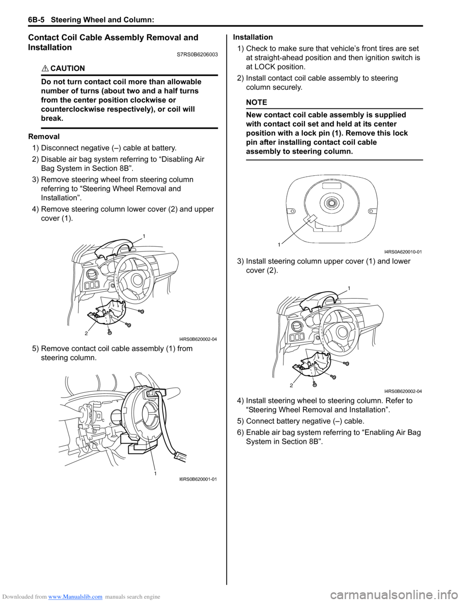
4) Remove steering column lower cover (2) and upper cover (1).
5) Remove contact coil cable assembly (1) from steering column. Installation
1) Check to make sure that vehicle’s front tires are set
at straight-ahead position and then ignition switch is
at LOCK position.
2) Install contact coil cable assembly to steering column securely.
NOTE
New contact coil cable assembly is supplied
with contact coil set and held at its center
position with a lock pin (1). Remove this lock
pin after installing contact coil cable
assembly to steering column.
3) Install steering column upper cover (1) and lower cover (2).
4) Install steering wheel to steering column. Refer to
“Steering Wheel Removal and Installation”.
5) Connect battery negative (–) cable.
6) Enable air bag system refe rring to “Enabling Air Bag
System in Section 8B”.
2
1
I4RS0B620002-04
1I6RS0B620001-01
I4RS0A620010-01
2
1
I4RS0B620002-04
Page 885 of 1496
Downloaded from www.Manualslib.com manuals search engine Power Assisted Steering System: 6C-3
EPS Diagnosis General DescriptionS7RS0B6301002
The P/S system in this vehicle is controlled by the P/S control module. T he P/S control module has an on-board
diagnostic system which detects a malfunction in this system. When diagnosing troubles, be sure to have full
understanding of the outline of “On-Board Diagnostic Sy stem Description” and each item in “Precautions in
Diagnosing Troubles”, and then execute diagnosis according to “EPS System Check”.
On-Board Diagnostic System DescriptionS7RS0B6301003
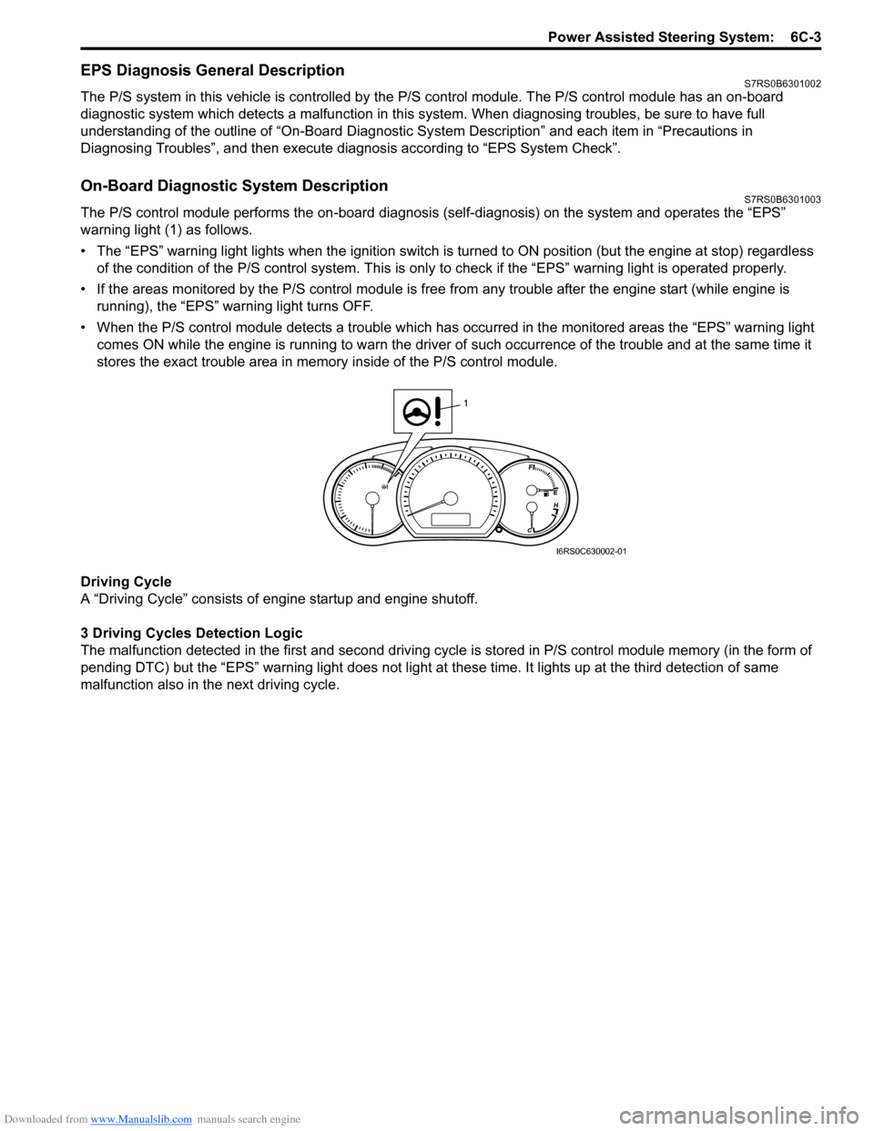
The P/S control module performs the on -board diagnosis (self-diagnosis) on the system and operates the “EPS”
warning light (1) as follows.
• The “EPS” warning light lights when the ignition switch is turned to ON position (but the engine at stop) regardless
of the condition of the P/S co ntrol system. This is only to check if the “EPS” warning light is operated properly.
• If the areas monitored by the P/S control module is free from any trouble after the engine start (while engine is
running), the “EPS” warning light turns OFF.
• When the P/S control module detects a trouble which has occurred in th e monitored areas the “EPS” warning light
comes ON while the engine is running to warn the driver of such occurrence of the trouble and at the same time it
stores the exact trouble area in memory inside of the P/S control module.
Driving Cycle
A “Driving Cycle” consists of en gine startup and engine shutoff.
3 Driving Cycles Detection Logic
The malfunction detected in the first and second driving cycl e is stored in P/S control module memory (in the form of
pending DTC) but the “EPS” wa rning light does not light at these time. It lights up at t he third detection of same
malfunction also in the next driving cycle.
1
I6RS0C630002-01
Page 888 of 1496
Downloaded from www.Manualslib.com manuals search engine 6C-6 Power Assisted Steering System:
NOTE
• As execution of “DTC Clearance” will clear all DTCs, be sure to record all DTCs before service.
• DTC C1122 is indicated when ignition switch is at ON position and engine is not running, it means
that nothing is abnormal.
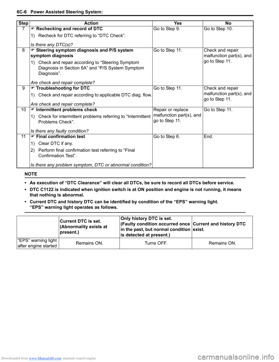
• Current DTC and history DTC ca n be identified by condition of the “EPS” warning light.
“EPS” warning light operates as follows.
7 �) Rechecking and record of DTC
1) Recheck for DTC referring to “DTC Check”.
Is there any DTC(s)? Go to Step 9. Go to Step 10.
8 �) Steering symptom diagnosis and P/S system
symptom diagnosis
1) Check and repair according to “Steering Symptom Diagnosis in Section 6A” and “P/S System Symptom
Diagnosis”.
Are check and repair complete? Go to Step 11. Check and repair
malfunction part(s), and
go to Step 11.
9 �) Troubleshooting for DTC
1) Check and repair according to applicable DTC diag. flow.
Are check and repair complete? Go to Step 11. Check and repair
malfunction part(s), and
go to Step 11.
10 �) Intermittent problems check
1) Check for intermittent problems referring to “Intermittent Problems Check”.
Is there any faulty condition? Repair or replace
malfunction part(s), and
go to Step 11.
Go to Step 11.
11 �) Final confirmation test
1) Clear DTC if any.
2) Perform final confirmation test referring to “Final Confirmation Test”.
Is there any problem symptom, DTC or abnormal condition? Go to Step 6. End.
Step Action Yes No
Current DTC is set.
(Abnormality exists at
present.)
Only history DTC is set.
(Faulty condition occurred once
in the past, but normal condition
is detected at present.)
Current and history DTC
exist.
“EPS” warning light
after engine started Remains ON. Turns OFF. Remains ON.
Page 926 of 1496
Downloaded from www.Manualslib.com manuals search engine 6C-44 Power Assisted Steering System:
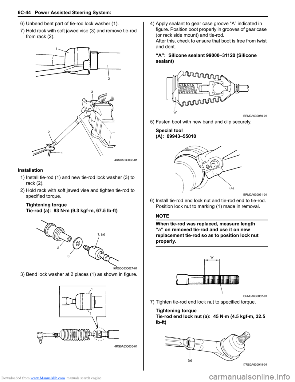
6) Unbend bent part of tie-rod lock washer (1).
7) Hold rack with soft jawed vise (3) and remove tie-rod
from rack (2).
Installation 1) Install tie-rod (1) and new tie-rod lock washer (3) to rack (2).
2) Hold rack with soft jawed vise and tighten tie-rod to specified torque.
Tightening torque
Tie-rod (a): 93 N·m (9.3 kgf-m, 67.5 lb-ft)
3) Bend lock washer at 2 places (1) as shown in figure. 4) Apply sealant to gear case groove “A” indicated in
figure. Position boot properly in grooves of gear case
(or rack side mount) and tie-rod.
After this, check to ensure that boot is free from twist
and dent.
“A”: Silicone sealant 99000–31120 (Silicone
sealant)
5) Fasten boot with new band and clip securely. Special tool
(A): 09943–55010
6) Install tie-rod end lock nut and tie-rod end to tie-rod. Position lock nut to marking (1) made in removal.
NOTE
When tie-rod was replaced, measure length
“a” on removed tie-rod and use it on new
replacement tie-rod so as to position lock nut
properly.
7) Tighten tie-rod end lock nut to specified torque.
Tightening torque
Tie-rod end lock nut (a): 45 N·m (4.5 kgf-m, 32.5
lb-ft)
I4RS0A630033-01
3 1, (a)
2
I6RS0C630027-01
I4RS0A630035-01
I3RM0A630050-01
I3RM0A630051-01
I3RM0A630052-01
(a)I7RS0A630018-01
Page 967 of 1496
Downloaded from www.Manualslib.com manuals search engine Air Conditioning System: Manual Type 7B-19
Charge
CAUTION!
• Because the sight glass is not used for this A/C system, do not perform an additional
charge to the A/C system. To charge the
proper amount of refrigerant, recover and
evacuate the A/C system first. And then,
charge the proper amount of refrigerant
into the A/C system.
• Always charge refrigerant through low pressure side of A/C system after the initial
charge is performed from the high
pressure side with the engine stopped.
• Never charge refrigerant through high pressure side of A/C system with engine
running.
• Do not charge refrigerant while compressor is hot.
• When installing tap valve to refrigerant container to make a hole there through,
carefully follow dire ctions given by
manufacturer.
• A pressure gauge should always be used before and during refrigerant charge.
• The refrigerant container should be emptied of refrigerant when discarding it.
• The refrigerant container should not be heated up to 40 °C (104 °F) or over.
• Refrigerant container should not be reversed in direction during refrigerant
charge. Reversing in direction causes
liquid refrigerant to enter compressor,
causing troubles, such as compression of
liquid refrigerant and the like.
NOTE
The air conditioning system contains HFC-
134a (R-134a).
Described here is a method to charge the air
conditioning system with refrigerant from the
refrigerant service container.
When charging refrigerant recovered by
using the refrigerant and recycling
equipment (when recycling refrigerant),
follow the procedure described in the
equipment manufacturer’s instruction
manual.
Charge proper amount of refrigerant accurately in
accordance with the following procedure.
Specified amount of refrigerant
370 ± 20 g (13.0 ± 0.7 oz)
The initial charge of the A/C system is performed
through the high pressure side with the engine stopped.
And next, this method must be followed by charging from
the low pressure side with the engine running.
1) Check if hoses are routed properly after evacuating the system.
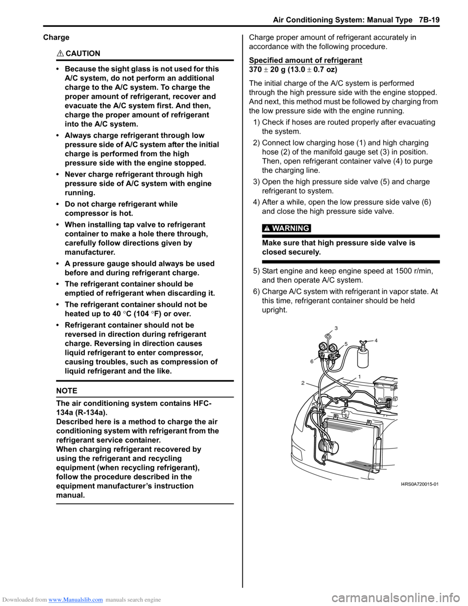
2) Connect low charging hose (1) and high charging hose (2) of the manifold gauge set (3) in position.
Then, open refrigerant container valve (4) to purge
the charging line.
3) Open the high pressure side valve (5) and charge refrigerant to system.
4) After a while, open the low pressure side valve (6) and close the high pressure side valve.
WARNING!
Make sure that high pressure side valve is
closed securely.
5) Start engine and keep engine speed at 1500 r/min, and then operate A/C system.
6) Charge A/C system with refrigerant in vapor state. At this time, refrigerant container should be held
upright.
1
2 6 3
5 4
I4RS0A720015-01
Page 1018 of 1496
Downloaded from www.Manualslib.com manuals search engine 7B-70 Air Conditioning System: Automatic Type
A/C System Performance InspectionS7RS0B7224027
Refer to “A/C System Performance Inspection”.
A/C System Inspection at ECMS7RS0B7224028
Voltage Check
ECM and its circuits can be checked by measuring voltage with special tool connected.
CAUTION!
• ECM connectors are waterproofed. Each terminal of the ECM connectors is sealed up with the
grommet. Therefore, do not measure circuit voltage and resistance by inserting the tester’s probe
into the sealed terminal at the harness side. Or, ECM and its circuits may be damaged by water.
• ECM cannot be checked by itself. It is strictly prohibited to connect voltmeter or ohmmeter to ECM with couplers disconnected from ECM.
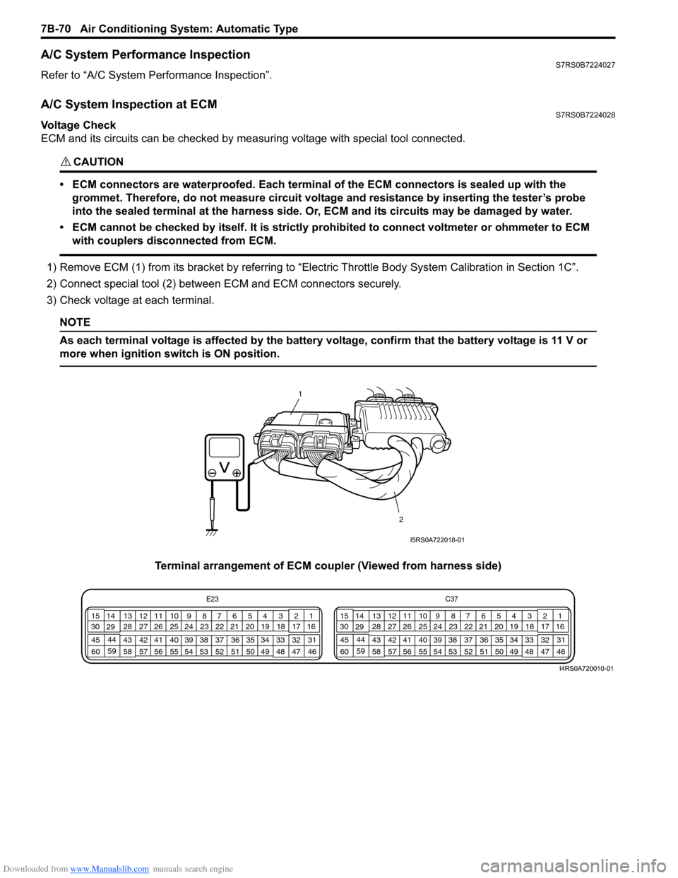
1) Remove ECM (1) from its bracket by referring to “Electric Throttle Body System Calibration in Section 1C”.
2) Connect special tool (2) between ECM and ECM connectors securely.
3) Check voltage at each terminal.
NOTE
As each terminal voltage is affected by the battery voltage, confirm that the battery voltage is 11 V or
more when ignition sw itch is ON position.
Terminal arrangement of ECM coupler (Viewed from harness side)
1
2
I5RS0A722018-01
E23 C37
34
1819
567
1011
17
20
47 46
495051
2122
52 16
25 9
24
14
29
55
57 54 53
59
60 58 2
262728
15
30
56 4832 31
34353637
40
42 39 38
44
45 43 41 331
1213
238
34
1819
567
1011
17
20
47 46
495051
2122
52 16
25 9
24
14
29
55
57 54 53
59
60 58 2
262728
15
30
56 4832 31
34353637
40
42 39 38
44
45 43 41 331
1213
238
I4RS0A720010-01
Page 1035 of 1496
Downloaded from www.Manualslib.com manuals search engine Seat Belts: 8A-4
Front Seat Belt Removal and InstallationS7RS0B8106002
WARNING!
• Never attempt to disassemble or repair the seat belt pretensioner (retractor
assembly). If any abnormality is found, be
sure to replace it with new one as an
assembly.
• Be sure to read “Precautions on Service and Diagnosis of Seat Belt” before starting
to work and observe every precaution
during work. Ne glecting them may result in
personal injury or una ctivation of the seat
belt pretensioner when necessary.
Removal
1) Disconnect negative (–) cable at battery.
2) Disable air bag system. Refer to “Disabling Air Bag System in Section 8B”.
3) Remove center pillar lower trim.
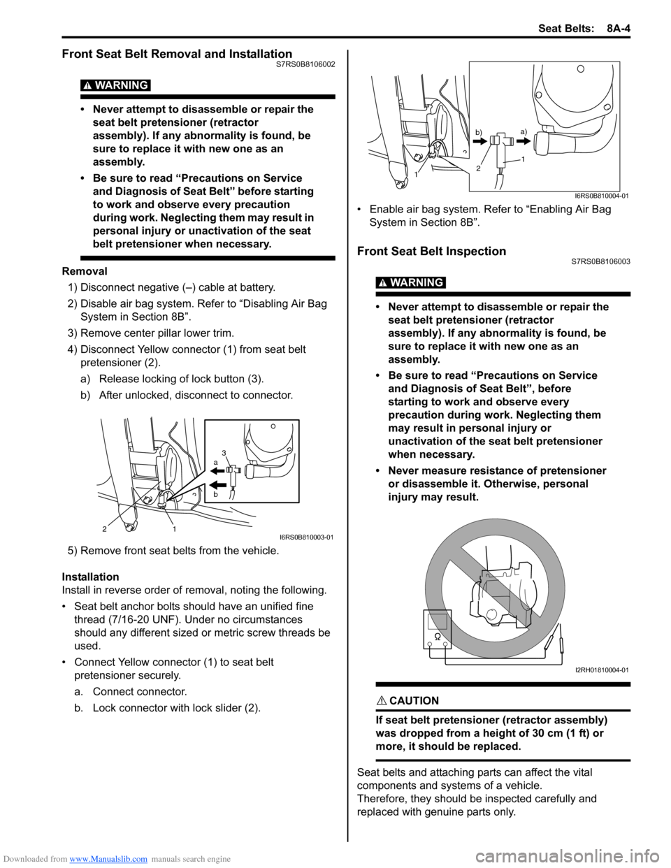
4) Disconnect Yellow connector (1) from seat belt pretensioner (2).
a) Release locking of lock button (3).
b) After unlocked, disconnect to connector.
5) Remove front seat belts from the vehicle.
Installation
Install in reverse order of removal, noting the following.
• Seat belt anchor bolts should have an unified fine thread (7/16-20 UNF). Under no circumstances
should any different sized or metric screw threads be
used.
• Connect Yellow connector (1) to seat belt pretensioner securely.
a. Connect connector.
b. Lock connector with lock slider (2). • Enable air bag system. Refer to “Enabling Air Bag
System in Section 8B”.
Front Seat Belt InspectionS7RS0B8106003
WARNING!
• Never attempt to disassemble or repair the seat belt pretensioner (retractor
assembly). If any abnormality is found, be
sure to replace it with new one as an
assembly.
• Be sure to read “Precautions on Service and Diagnosis of Seat Belt”, before
starting to work and observe every
precaution during work. Neglecting them
may result in personal injury or
unactivation of the seat belt pretensioner
when necessary.
• Never measure resistance of pretensioner or disassemble it. Otherwise, personal
injury may result.
CAUTION!
If seat belt pretensioner (retractor assembly)
was dropped from a height of 30 cm (1 ft) or
more, it should be replaced.
Seat belts and attaching parts can affect the vital
components and systems of a vehicle.
Therefore, they should be inspected carefully and
replaced with genuine parts only.
a
b
21 3I6RS0B810003-01
1
1
2
b)
a)
I6RS0B810004-01
I2RH01810004-01
Page 1036 of 1496
Downloaded from www.Manualslib.com manuals search engine 8A-5 Seat Belts:
Seat Belt
• The seat belt webbing or strap should be free from damage.
Retractor Assembly (with Seat Belt Pretensioner) 1) Let the seat belt retract fully to confirm its easy retraction.
• The retractor assembly should lock webbing when
pulled quickly.
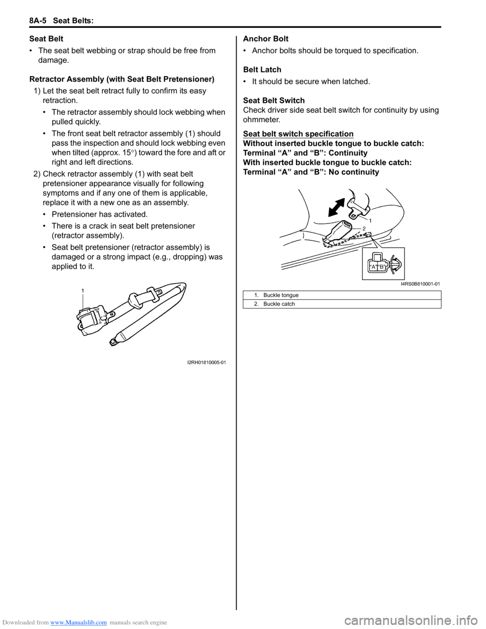
• The front seat belt retractor assembly (1) should pass the inspection and should lock webbing even
when tilted (approx. 15 °) toward the fore and aft or
right and left directions.
2) Check retractor assembly (1) with seat belt pretensioner appearance visually for following
symptoms and if any one of them is applicable,
replace it with a new one as an assembly.
• Pretensioner has activated.
• There is a crack in seat belt pretensioner (retractor assembly).
• Seat belt pretensioner (retractor assembly) is damaged or a strong impact (e.g., dropping) was
applied to it. Anchor Bolt
• Anchor bolts should be torqued to specification.
Belt Latch
• It should be secure when latched.
Seat Belt Switch
Check driver side seat belt s
witch for continuity by using
ohmmeter.
Seat belt switch specification
Without inserted buckle tongue to buckle catch:
Terminal “A” and “B”: Continuity
With inserted buckle tongue to buckle catch:
Terminal “A” and “B”: No continuity
I2RH01810005-01
1. Buckle tongue
2. Buckle catch
I4RS0B810001-01
Page 1041 of 1496
Downloaded from www.Manualslib.com manuals search engine Air Bag System: 8B-3
• Never attempt disassembly of the air bag (inflator) modules.
• If any abnormality is found, be sure to replace it with
new one as an assembly.
• When an abnormality is noted as existing in the live (undeployed) air bag (inflator) module, be sure to
deploy it before discarding it.
• When grease, cleaning agent, oil, water, etc., got on the air bag (inflator) modules (driver, passenger, side
of both sides and curtain of both sides), wipe it off
immediately with a dry cloth.
• If air bag (inflator) module was dropped from a height of 90 cm (3 ft) or more, it should be replaced with a
new one as an assembly.
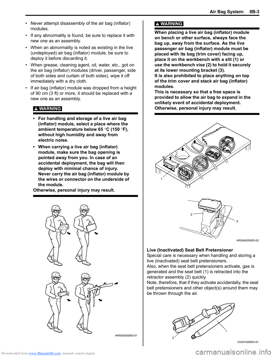
WARNING!
• For handling and storage of a live air bag (inflator) module, select a place where the
ambient temperature below 65 °C (150 ° F),
without high humidity and away from
electric noise.
• When carrying a live air bag (inflator) module, make sure the bag opening is
pointed away from you. In case of an
accidental deployment, the bag will then
deploy with minimal chance of injury.
Never carry the air bag (inflator) module by
the wires or connector on the underside of
the module.
Otherwise, personal injury may result.
WARNING!
When placing a live air bag (inflator) module
on bench or other surface, always face the
bag up, away from the surface. As the live
passenger air bag (inflator) module must be
placed with its bag (trim cover) facing up,
place it on the workbench with a slit (1) or
use the workbench vise (2) to hold it securely
at its lower mounting bracket (3).
It is also prohibited to place anything on top
of the trim cover and stack air bag (inflator)
modules.
This is necessary so that a free space is
provided to allow the air bag to expand in the
unlikely event of accidental deployment.
Otherwise, personal injury may result.
Live (Inactivated) Seat Belt Pretensioner
Special care is necessary when handling and storing a
live (inactivated) seat belt pretensioners.
Also, when the seat belt pretensioners activate, gas is
generated and the seat belt (1) is retracted into the
retractor assembly (2) quickly.
Note, therefore, that if they activate accidentally, the seat
belt pretensioners and other object(s) around them may
be thrown through the air.
I4RS0A820002-01
1
2
3
I4RS0A820003-02
I3JA01820043-01
Page 1043 of 1496
Downloaded from www.Manualslib.com manuals search engine Air Bag System: 8B-5
• When an open in air bag wire harness, damaged wire harness, connector or terminal is found, replace wire
harness, connectors and terminals as an assembly.
• When installing it, be careful so that the air bag wire harness is not caught or does not interfere with other
parts.
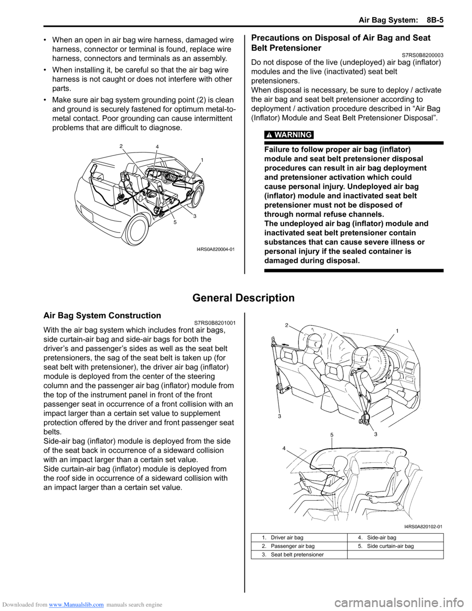
• Make sure air bag system grounding point (2) is clean and ground is securely fastened for optimum metal-to-
metal contact. Poor grounding can cause intermittent
problems that are difficult to diagnose.Precautions on Disposal of Air Bag and Seat
Belt Pretensioner
S7RS0B8200003
Do not dispose of the live (undeployed) air bag (inflator)
modules and the live (inactivated) seat belt
pretensioners.
When disposal is necessary, be sure to deploy / activate
the air bag and seat belt pretensioner according to
deployment / activation procedure described in “Air Bag
(Inflator) Module and Seat Belt Pretensioner Disposal”.
WARNING!
Failure to follow proper air bag (inflator)
module and seat belt pretensioner disposal
procedures can result in air bag deployment
and pretensioner activation which could
cause personal injury. Undeployed air bag
(inflator) module and inactivated seat belt
pretensioner must not be disposed of
through normal refuse channels.
The undeployed air bag (inflator) module and
inactivated seat belt pretensioner contain
substances that can cause severe illness or
personal injury if the sealed container is
damaged during disposal.
General Description
Air Bag System ConstructionS7RS0B8201001
With the air bag system which includes front air bags,
side curtain-air bag and side-air bags for both the
driver’s and passenger’s sides as well as the seat belt
pretensioners, the sag of the s eat belt is taken up (for
seat belt with pretensioner), the driver air bag (inflator)
module is deployed from th e center of the steering
column and the passenger air bag (inflator) module from
the top of the instrument panel in front of the front
passenger seat in occurrence of a front collision with an
impact larger than a certain set value to supplement
protection offered by the driver and front passenger seat
belts.
Side-air bag (inflator) module is deployed from the side
of the seat back in occurrence of a sideward collision
with an impact larger than a certain set value.
Side curtain-air bag (inflator) module is deployed from
the roof side in occurrence of a sideward collision with
an impact larger than a certain set value.
1
2
3
4
5
I4RS0A820004-01
1. Driver air bag 4. Side-air bag
2. Passenger air bag 5. Side curtain-air bag
3. Seat belt pretensioner
I4RS0A820102-01