brake caliper SUZUKI SWIFT 2005 2.G Service Workshop Manual
[x] Cancel search | Manufacturer: SUZUKI, Model Year: 2005, Model line: SWIFT, Model: SUZUKI SWIFT 2005 2.GPages: 1496, PDF Size: 34.44 MB
Page 37 of 1496
Downloaded from www.Manualslib.com manuals search engine Maintenance and Lubrication: 0B-7
Fuel Filter ReplacementS7RS0B0206011
Fuel filter is installed in fuel pump assembly in fuel tank.
Replace fuel filter or fuel pump assembly with new one,
referring to “Fuel Pump Assembly Removal and
Installation in Section 1G” for proper procedure.
Fuel Tank InspectionS7RS0B0206012
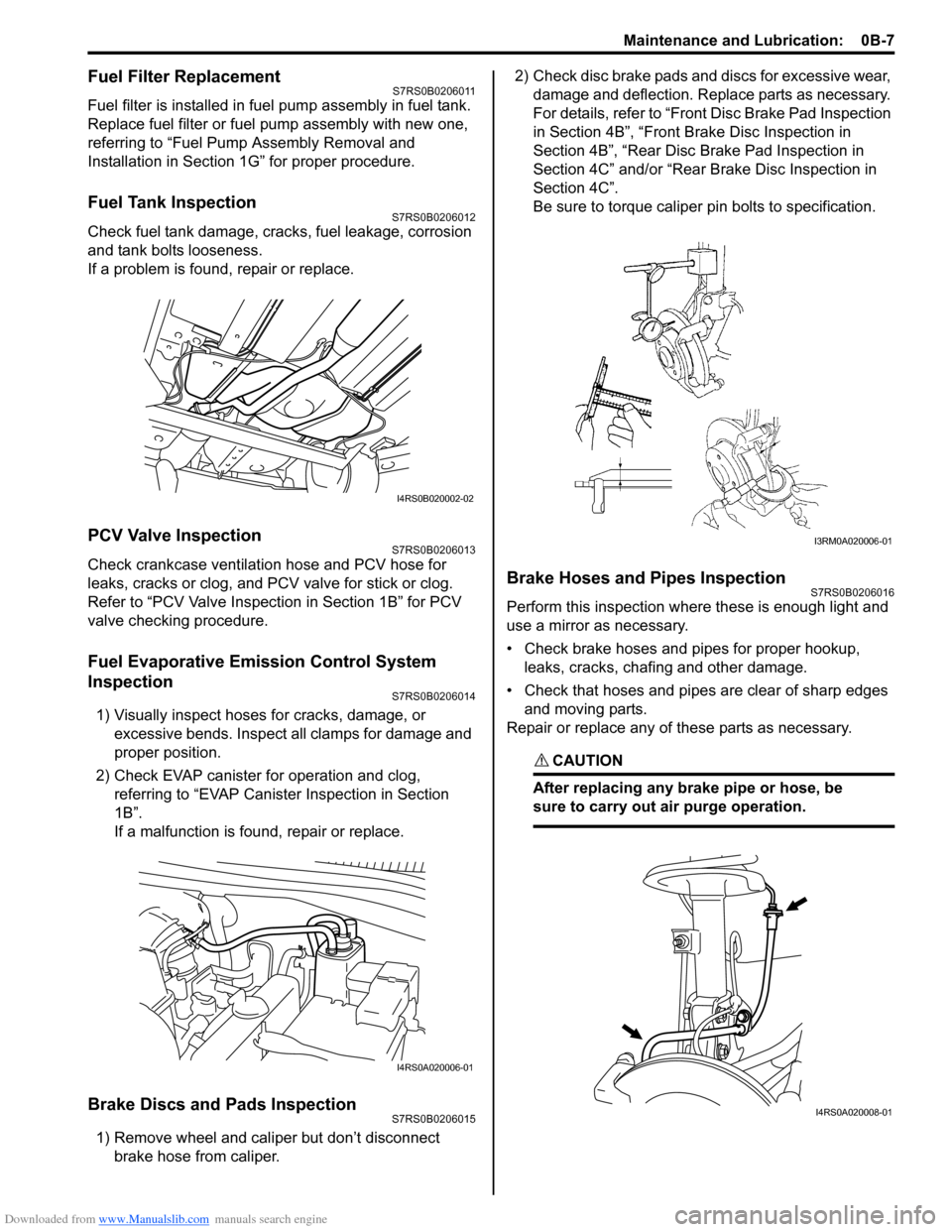
Check fuel tank damage, cracks, fuel leakage, corrosion
and tank bolts looseness.
If a problem is found, repair or replace.
PCV Valve InspectionS7RS0B0206013
Check crankcase ventilation hose and PCV hose for
leaks, cracks or clog, and PCV valve for stick or clog.
Refer to “PCV Valve Inspection in Section 1B” for PCV
valve checking procedure.
Fuel Evaporative Emission Control System
Inspection
S7RS0B0206014
1) Visually inspect hoses for cracks, damage, or excessive bends. Inspect a ll clamps for damage and
proper position.
2) Check EVAP canister for operation and clog, referring to “EVAP Canister Inspection in Section
1B”.
If a malfunction is found, repair or replace.
Brake Discs and Pads InspectionS7RS0B0206015
1) Remove wheel and caliper but don’t disconnect brake hose from caliper. 2) Check disc brake pads and discs for excessive wear,
damage and deflection. Replace parts as necessary.
For details, refer to “Front Disc Brake Pad Inspection
in Section 4B”, “Front Brake Disc Inspection in
Section 4B”, “Rear Disc Brake Pad Inspection in
Section 4C” and/or “Rear Brake Disc Inspection in
Section 4C”.
Be sure to torque caliper pin bolts to specification.
Brake Hoses and Pipes InspectionS7RS0B0206016
Perform this inspection where these is enough light and
use a mirror as necessary.
• Check brake hoses and pipes for proper hookup, leaks, cracks, chafing and other damage.
• Check that hoses and pipes are clear of sharp edges and moving parts.
Repair or replace any of these parts as necessary.
CAUTION!
After replacing any brake pipe or hose, be
sure to carry out air purge operation.
I4RS0B020002-02
I4RS0A020006-01
I3RM0A020006-01
I4RS0A020008-01
Page 444 of 1496
Downloaded from www.Manualslib.com manuals search engine 2B-11 Front Suspension:
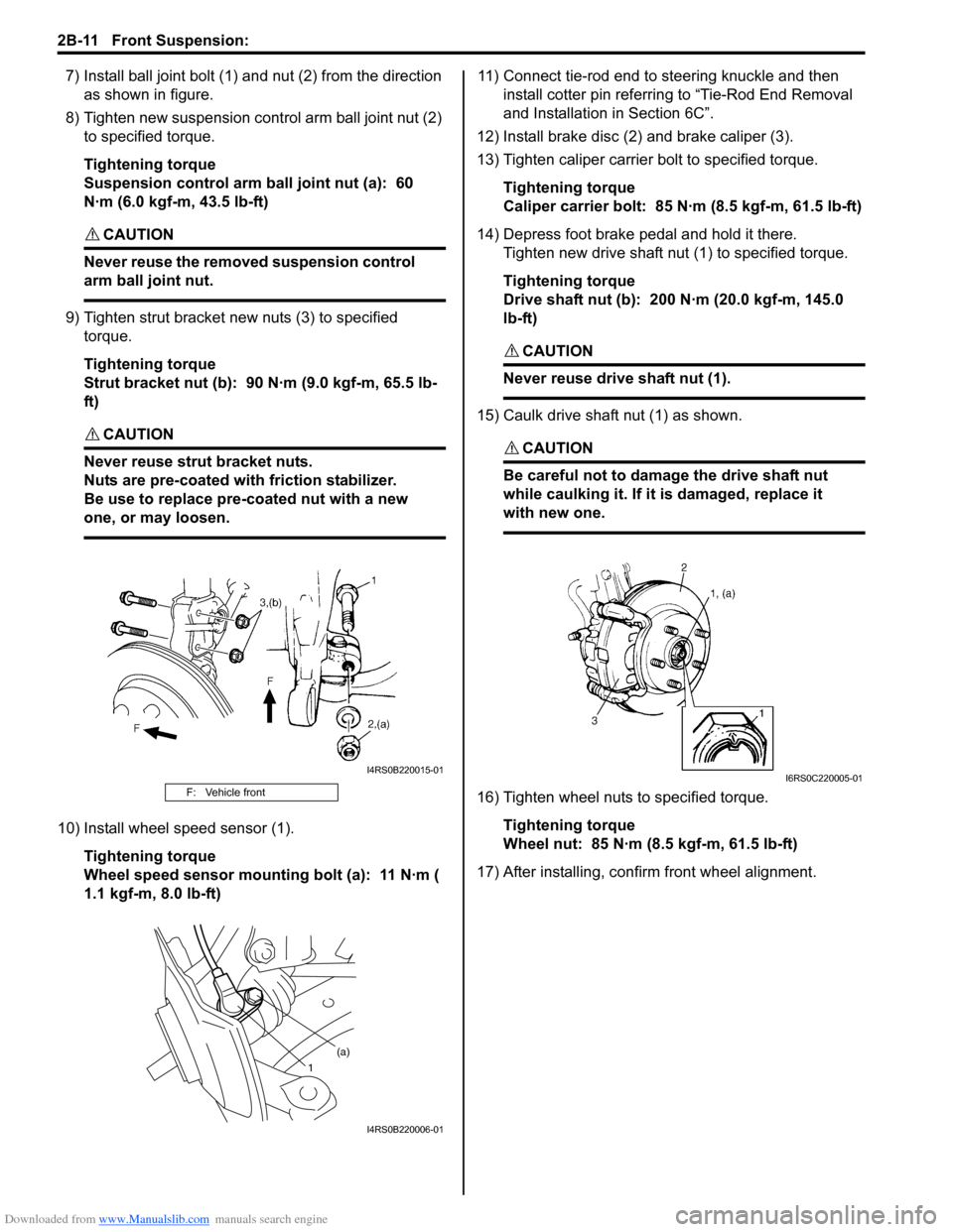
7) Install ball joint bolt (1) and nut (2) from the direction
as shown in figure.
8) Tighten new suspension co ntrol arm ball joint nut (2)
to specified torque.
Tightening torque
Suspension control arm ball joint nut (a): 60
N·m (6.0 kgf-m, 43.5 lb-ft)
CAUTION!
Never reuse the removed suspension control
arm ball joint nut.
9) Tighten strut bracket new nuts (3) to specified torque.
Tightening torque
Strut bracket nut (b): 90 N·m (9.0 kgf-m, 65.5 lb-
ft)
CAUTION!
Never reuse strut bracket nuts.
Nuts are pre-coated with friction stabilizer.
Be use to replace pre-coated nut with a new
one, or may loosen.
10) Install wheel speed sensor (1).
Tightening torque
Wheel speed sensor mounting bolt (a): 11 N·m (
1.1 kgf-m, 8.0 lb-ft) 11) Connect tie-rod end to steering knuckle and then
install cotter pin referrin g to “Tie-Rod End Removal
and Installation in Section 6C”.
12) Install brake disc (2) and brake caliper (3).
13) Tighten caliper carrier bolt to specified torque.
Tightening torque
Caliper carrier bolt: 85 N·m (8.5 kgf-m, 61.5 lb-ft)
14) Depress foot brake pedal and hold it there. Tighten new drive shaft nut (1) to specified torque.
Tightening torque
Drive shaft nut (b): 200 N·m (20.0 kgf-m, 145.0
lb-ft)
CAUTION!
Never reuse drive shaft nut (1).
15) Caulk drive shaft nut (1) as shown.
CAUTION!
Be careful not to damage the drive shaft nut
while caulking it. If it is damaged, replace it
with new one.
16) Tighten wheel nuts to specified torque.
Tightening torque
Wheel nut: 85 N·m (8.5 kgf-m, 61.5 lb-ft)
17) After installing, confirm front wheel alignment.F: Vehicle front
I4RS0B220015-01
1 (a)
I4RS0B220006-01
I6RS0C220005-01
Page 453 of 1496
Downloaded from www.Manualslib.com manuals search engine Front Suspension: 2B-20
Specifications
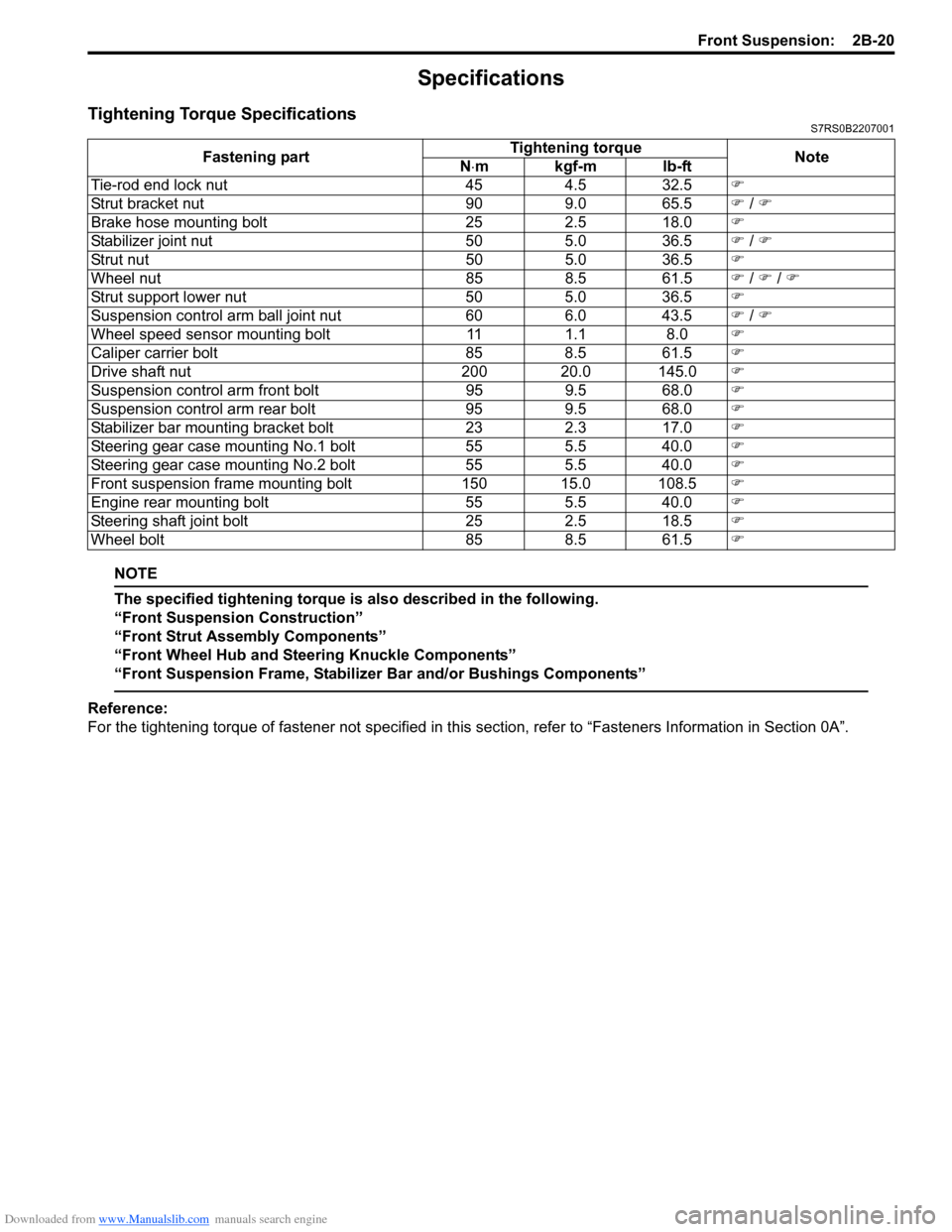
Tightening Torque SpecificationsS7RS0B2207001
NOTE
The specified tightening torque is also described in the following.
“Front Suspension Construction”
“Front Strut Assembly Components”
“Front Wheel Hub and Steering Knuckle Components”
“Front Suspension Frame, Stabilizer Bar and/or Bushings Components”
Reference:
For the tightening torque of fastener not specified in this section, refer to “Fasteners Information in Section 0A”.
Fastening part
Tightening torque
Note
N ⋅mkgf-mlb-ft
Tie-rod end lock nut 454.5 32.5 �)
Strut bracket nut 909.0 65.5 �) / �)
Brake hose mounting bolt 252.5 18.0 �)
Stabilizer joint nut 505.0 36.5 �) / �)
Strut nut 505.0 36.5 �)
Wheel nut 858.5 61.5 �) / �) / �)
Strut support lower nut 505.0 36.5 �)
Suspension control arm ball joint nut 606.0 43.5 �) / �)
Wheel speed sensor mounting bolt 111.1 8.0 �)
Caliper carrier bolt 858.5 61.5 �)
Drive shaft nut 200 20.0 145.0�)
Suspension control arm front bolt 959.5 68.0 �)
Suspension control arm rear bolt 959.5 68.0 �)
Stabilizer bar mounting bracket bolt 232.3 17.0 �)
Steering gear case mounting No.1 bolt 555.5 40.0 �)
Steering gear case mounting No.2 bolt 555.5 40.0 �)
Front suspension frame mounting bolt 150 15.0 108.5�)
Engine rear mounting bolt 555.5 40.0 �)
Steering shaft joint bolt 252.5 18.5 �)
Wheel bolt 858.5 61.5 �)
Page 460 of 1496
Downloaded from www.Manualslib.com manuals search engine 2C-6 Rear Suspension:
Spring Upper Seat and Lower Seat Removal and
Installation
S7RS0B2306007
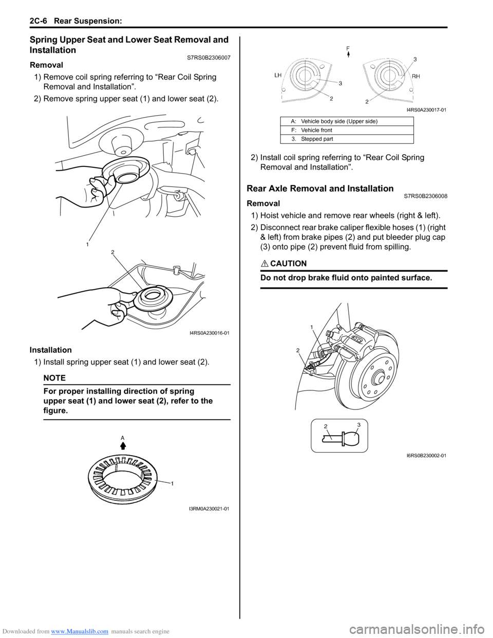
Removal1) Remove coil spring referring to “Rear Coil Spring Removal and Installation”.
2) Remove spring upper seat (1) and lower seat (2).
Installation 1) Install spring upper seat (1) and lower seat (2).
NOTE
For proper installing direction of spring
upper seat (1) and lower seat (2), refer to the
figure.
2) Install coil spring referr ing to “Rear Coil Spring
Removal and Installation”.
Rear Axle Removal and InstallationS7RS0B2306008
Removal
1) Hoist vehicle and remove rear wheels (right & left).
2) Disconnect rear brake caliper flexible hoses (1) (right & left) from brake pipes (2) and put bleeder plug cap
(3) onto pipe (2) prevent fluid from spilling.
CAUTION!
Do not drop brake fluid onto painted surface.
1
2
I4RS0A230016-01
I3RM0A230021-01
A: Vehicle body side (Upper side)
F: Vehicle front3. Stepped part
I4RS0A230017-01
1
2
2 3
I6RS0B230002-01
Page 461 of 1496
Downloaded from www.Manualslib.com manuals search engine Rear Suspension: 2C-7
3) Remove rear brake caliper assemblies (right & left)
and brake discs (right & left ). For details, refer to
Step 2) to 3) of “Removal” under “Rear Brake Disc
Removal and Installa tion in Section 4C”.
4) Remove rear wheel hubs (r ight & left). For details,
refer to Step 3) to 5) of “Removal” under “Rear
Wheel Hub Removal and Installation”.
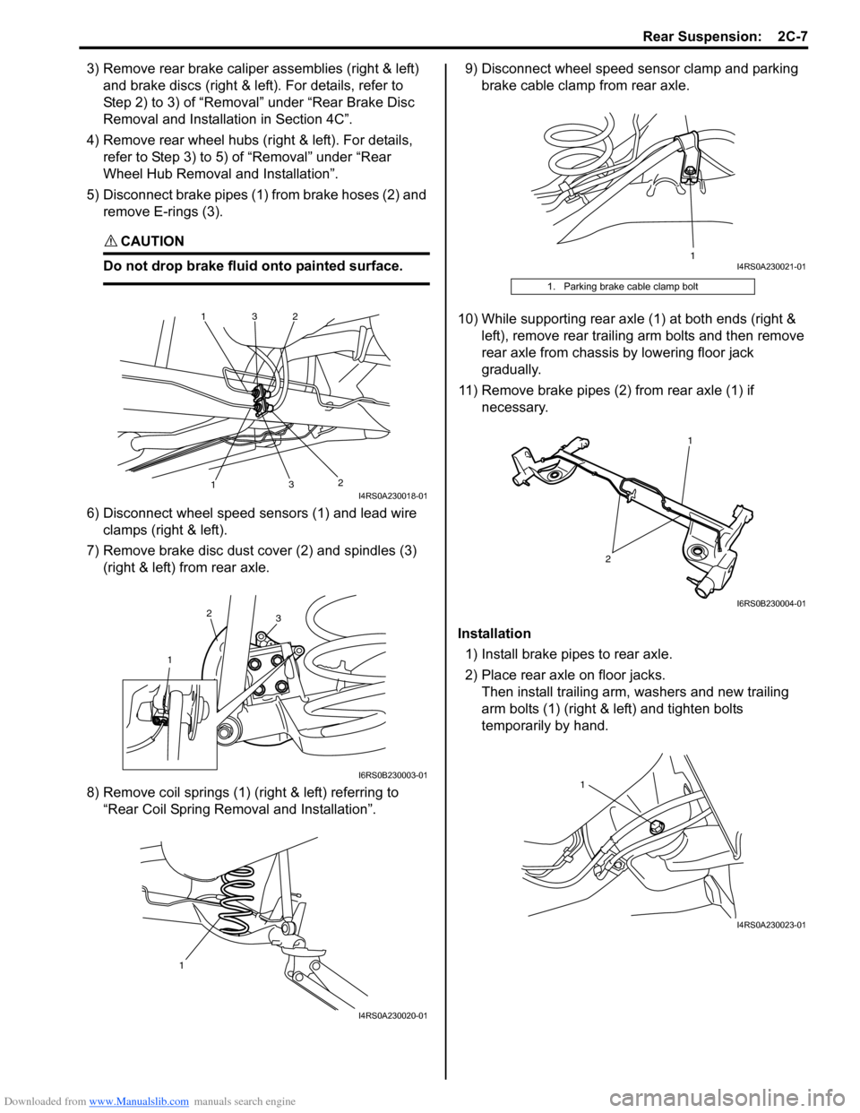
5) Disconnect brake pipes (1) from brake hoses (2) and remove E-rings (3).
CAUTION!
Do not drop brake fluid onto painted surface.
6) Disconnect wheel speed sensors (1) and lead wire clamps (right & left).
7) Remove brake disc dust cover (2) and spindles (3) (right & left) from rear axle.
8) Remove coil springs (1) (right & left) referring to “Rear Coil Spring Removal and Installation”. 9) Disconnect wheel speed sensor clamp and parking
brake cable clamp from rear axle.
10) While supporting rear axle (1) at both ends (right & left), remove rear trailing arm bolts and then remove
rear axle from chassis by lowering floor jack
gradually.
11) Remove brake pipes (2) from rear axle (1) if necessary.
Installation 1) Install brake pipes to rear axle.
2) Place rear axle on floor jacks. Then install trailing arm, washers and new trailing
arm bolts (1) (right & left) and tighten bolts
temporarily by hand.
1
1
2
2
3
3I4RS0A230018-01
1
2
3
I6RS0B230003-01
1
I4RS0A230020-01
1. Parking brake cable clamp bolt
1I4RS0A230021-01
2
1
I6RS0B230004-01
1
I4RS0A230023-01
Page 462 of 1496
Downloaded from www.Manualslib.com manuals search engine 2C-8 Rear Suspension:
3) Install coil springs (right & left) on spring seats of rear
axle referring to “Spring Upper Seat and Lower Seat
Removal and Installation” and “Rear Coil Spring
Removal and Installation”.
4) Install shock absorbers lower side (right & left) and washers referring to “Rear Shock Absorber Removal
and Installation”.
5) Install brake dust covers, spindles and wheel speed sensors (right and left) referring to “Spindle Removal
and Installation”.
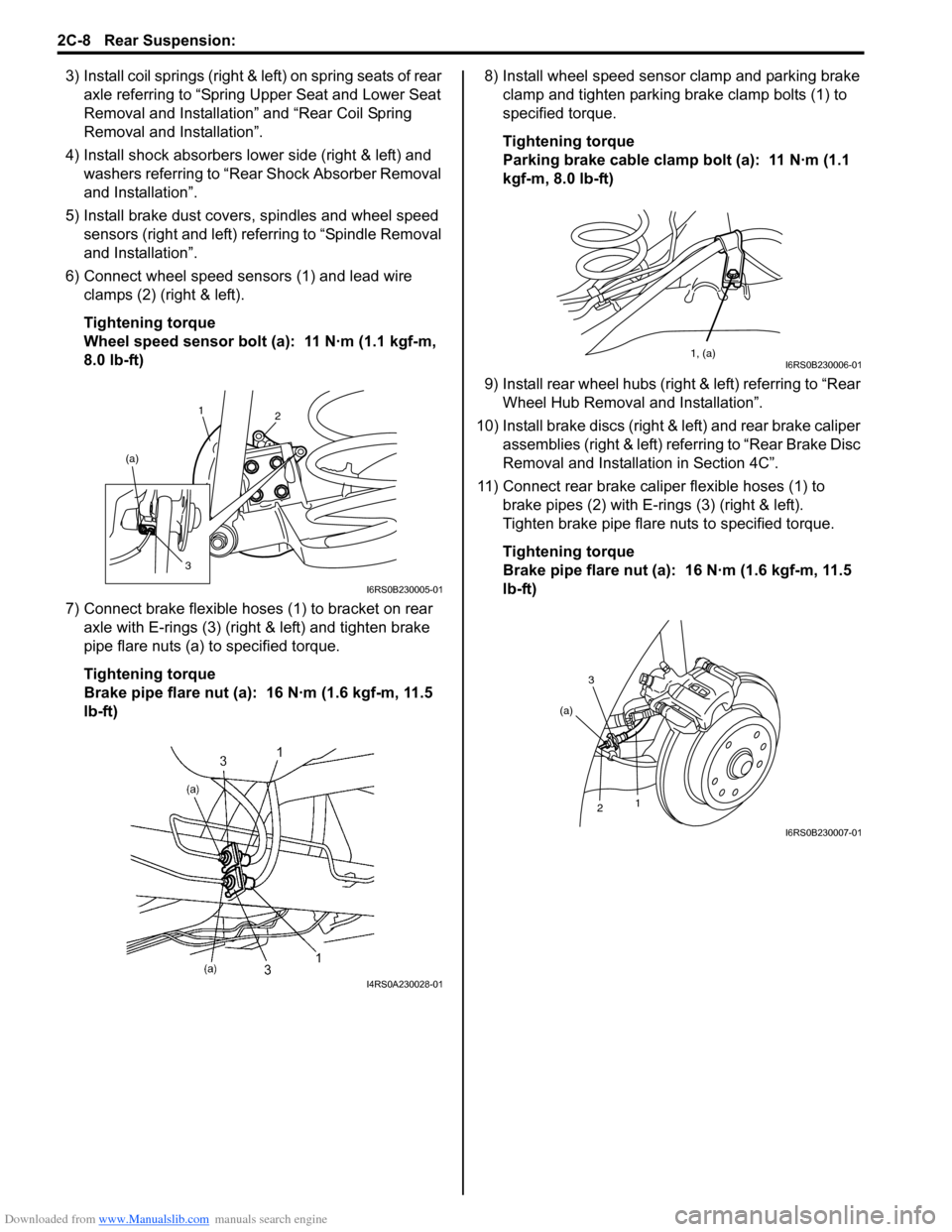
6) Connect wheel speed sensors (1) and lead wire clamps (2) (right & left).
Tightening torque
Wheel speed sensor bolt (a): 11 N·m (1.1 kgf-m,
8.0 lb-ft)
7) Connect brake flexible hoses (1) to bracket on rear axle with E-rings (3) (right & left) and tighten brake
pipe flare nuts (a) to specified torque.
Tightening torque
Brake pipe flare nut (a): 16 N·m (1.6 kgf-m, 11.5
lb-ft) 8) Install wheel speed sensor clamp and parking brake
clamp and tighten parking brake clamp bolts (1) to
specified torque.
Tightening torque
Parking brake cable clamp bolt (a): 11 N·m (1.1
kgf-m, 8.0 lb-ft)
9) Install rear wheel hubs (right & left) referring to “Rear Wheel Hub Removal and Installation”.
10) Install brake discs (right & left) and rear brake caliper assemblies (right & left) referring to “Rear Brake Disc
Removal and Installati on in Section 4C”.
11) Connect rear brake caliper flexible hoses (1) to brake pipes (2) with E-rings (3) (right & left).
Tighten brake pipe flare nuts to specified torque.
Tightening torque
Brake pipe flare nut (a): 16 N·m (1.6 kgf-m, 11.5
lb-ft)
1 2
(a)
3
I6RS0B230005-01
I4RS0A230028-01
1, (a)I6RS0B230006-01
3
2 1
(a)
I6RS0B230007-01
Page 464 of 1496
Downloaded from www.Manualslib.com manuals search engine 2C-10 Rear Suspension:
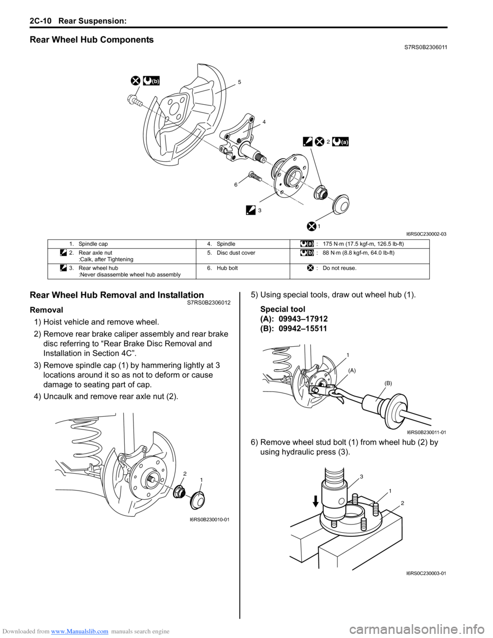
Rear Wheel Hub ComponentsS7RS0B2306011
Rear Wheel Hub Removal and InstallationS7RS0B2306012
Removal1) Hoist vehicle and remove wheel.
2) Remove rear brake caliper assembly and rear brake disc referring to “Rear Brake Disc Removal and
Installation in Section 4C”.
3) Remove spindle cap (1) by hammering lightly at 3 locations around it so as not to deform or cause
damage to seating part of cap.
4) Uncaulk and remove rear axle nut (2). 5) Using special tools, draw out wheel hub (1).
Special tool
(A): 09943–17912
(B): 09942–15511
6) Remove wheel stud bolt (1) from wheel hub (2) by using hydraulic press (3).
(b)5
4
3
(a)2
1
6
I6RS0C230002-03
1. Spindle cap 4. Spindle: 175 N⋅m (17.5 kgf-m, 126.5 lb-ft)
2. Rear axle nut :Calk, after Tightening 5. Disc dust cover
: 88 N⋅m (8.8 kgf-m, 64.0 lb-ft)
3. Rear wheel hub :Never disassemble wheel hub assembly 6. Hub bolt
: Do not reuse.
2
1
I6RS0B230010-01
1
(A) (B)
I6RS0B230011-01
1
3
2
I6RS0C230003-01
Page 466 of 1496
Downloaded from www.Manualslib.com manuals search engine 2C-12 Rear Suspension:
• Check noise and smooth rotation of wheel by rotating wheel. If it is defect ive, replace bearing.
Spindle Removal and InstallationS7RS0B2306014
Removal
1) Remove rear brake caliper assembly and brake disc. For details, refer to Step 2) to 4) of “Removal” under
“Rear Brake Disc Removal and Installation in
Section 4C”.
2) Remove rear wheel hub. For details, refer to Step 3) to 5) of “Removal” under “Rear Wheel Hub Removal
and Installation”.
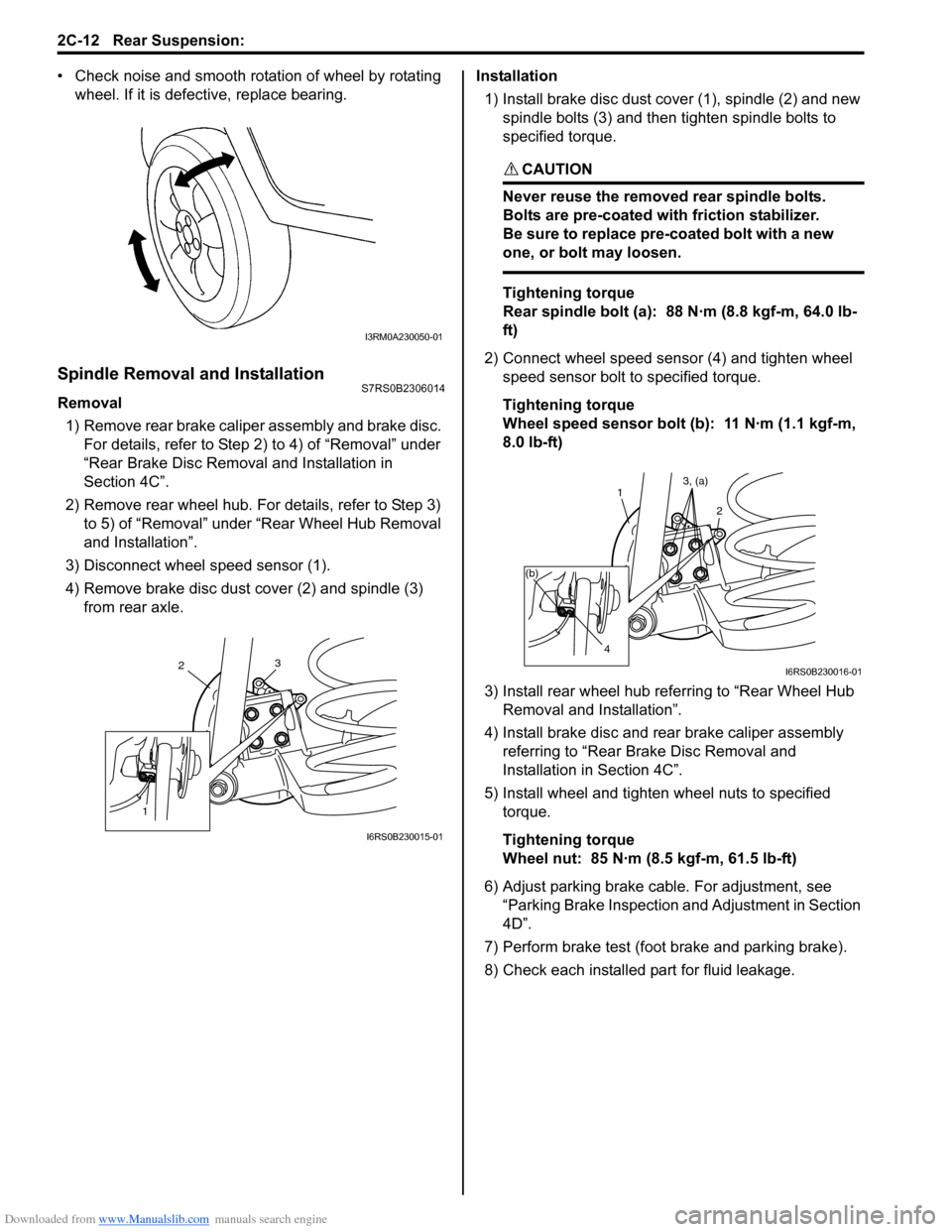
3) Disconnect wheel speed sensor (1).
4) Remove brake disc dust cover (2) and spindle (3) from rear axle. Installation
1) Install brake disc dust cover (1), spindle (2) and new spindle bolts (3) and then tighten spindle bolts to
specified torque.
CAUTION!
Never reuse the removed rear spindle bolts.
Bolts are pre-coated wi th friction stabilizer.
Be sure to replace pre-coated bolt with a new
one, or bolt may loosen.
Tightening torque
Rear spindle bolt (a): 88 N·m (8.8 kgf-m, 64.0 lb-
ft)
2) Connect wheel speed sensor (4) and tighten wheel speed sensor bolt to specified torque.
Tightening torque
Wheel speed sensor bolt (b): 11 N·m (1.1 kgf-m,
8.0 lb-ft)
3) Install rear wheel hub re ferring to “Rear Wheel Hub
Removal and Installation”.
4) Install brake disc and rear brake caliper assembly referring to “Rear Brake Disc Removal and
Installation in Section 4C”.
5) Install wheel and tighten wheel nuts to specified torque.
Tightening torque
Wheel nut: 85 N·m (8.5 kgf-m, 61.5 lb-ft)
6) Adjust parking brake cable. For adjustment, see “Parking Brake Inspection and Adjustment in Section
4D”.
7) Perform brake test (foot brake and parking brake).
8) Check each installed part for fluid leakage.
I3RM0A230050-01
2
1 3
I6RS0B230015-01
1
(b)
4
2
3, (a)
I6RS0B230016-01
Page 495 of 1496
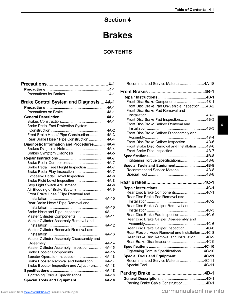
Downloaded from www.Manualslib.com manuals search engine Table of Contents 4- i
4
Section 4
CONTENTS
Brakes
Precautions ................................................. 4-1
Precautions............................................................. 4-1
Precautions for Brakes .......................................... 4-1
Brake Control System and Diagnosis ... 4A-1
Precautions........................................................... 4A-1Precautions on Brake .......................................... 4A-1
General Description ............................................. 4A-1 Brakes Construction ............................................ 4A-1
Brake Pedal Foot Protection System Construction ...................................................... 4A-2
Front Brake Hose / Pipe Co nstruction................. 4A-3
Rear Brake Hose / Pipe Construction ................. 4A-4
Diagnostic Information and Procedures ............ 4A-4 Brakes Diagnosis Note ....................................... 4A-4
Brakes Symptom Diagnosis ................................ 4A-5
Repair Instructions .............................................. 4A-7 Brake Pedal Components ................................... 4A-7
Brake Pedal Free Height Inspection ................... 4A-7
Brake Pedal Play Inspection ............................... 4A-7
Excessive Pedal Travel Inspection ..................... 4A-8
Brake Fluid Level Inspection ............................... 4A-8
Stop Light Switch Adjustment ............................. 4A-8
Air Bleeding of Brake System ............................. 4A-9
Front Brake Hose / Pipe Removal and Installation ....................................................... 4A-10
Rear Brake Hose / Pipe Removal and Installation ....................................................... 4A-10
Brake Hose and Pipe Inspection ....................... 4A-11
Master Cylinder Components............................ 4A-11
Master Cylinder Assembly Removal and Installation ....................................................... 4A-12
Master Cylinder Rese rvoir Removal and
Installation ....................................................... 4A-13
Master Cylinder Assemb ly Disassembly and
Assembly ........................................................ 4A-14
Master Cylinder Assembly Inspection ............... 4A-15
Brake Booster Components .............................. 4A-15
Booster Operation Inspection ........................... 4A-16
Brake Booster Removal and Installation ........... 4A-17
Brake Booster Inspection and Adjustment ........ 4A-18
Specifications ..................................................... 4A-18
Tightening Torque Specifications ...................... 4A-18
Special Tools and Equipmen t ........................... 4A-18 Recommended Service Material ....................... 4A-18
Front Brakes .......
..................................... 4B-1
Repair Instructions ........... ...................................4B-1
Front Disc Brake Components ............................ 4B-1
Front Disc Brake Pad On-Vehicle Inspection ...... 4B-2
Front Disc Brake Pad Removal and Installation ......................................................... 4B-2
Front Disc Brake Pad Inspection......................... 4B-3
Front Disc Brake Ca liper Removal and
Installation ......................................................... 4B-3
Front Disc Brake Caliper Disassembly and Assembly........................................................... 4B-4
Front Disc Brake Caliper In spection.................... 4B-6
Front Brake Disc Removal and Installation ......... 4B-6
Front Brake Disc Inspection ................................ 4B-7
Specifications .................... ...................................4B-8
Tightening Torque Specifications ........................ 4B-8
Special Tools and Equipmen t .............................4B-8
Recommended Service Material ......................... 4B-8
Special Tool ........................................................ 4B-8
Rear Brakes................... ........................... 4C-1
Repair Instructions ........... ...................................4C-1
Rear Disc Brake Components.............................4C-1
Rear Disc Brake Pad Removal and Installation .........................................................4C-2
Rear Disc Brake Caliper Removal and Installation .........................................................4C-3
Rear Disc Brake Pad Inspection .........................4C-6
Rear Disc Brake Caliper Disassembly and Assembly...........................................................4C-6
Rear Disc Brake Caliper Inspection ....................4C-8
Rear Flexible Hose Remova l and Installation .....4C-8
Rear Brake Disc Removal and Installation..........4C-9
Rear Brake Disc Inspection.................................4C-9
Specifications .................... .................................4C-10
Tightening Torque Specifications ......................4C-10
Special Tools and Equipmen t ...........................4C-11
Recommended Service Material .......................4C-11
Special Tool ......................................................4C-11
Parking Brake ................. ......................... 4D-1
General Description .............................................4D-1
Parking Brake Cable Construction ......................4D-1
Page 502 of 1496
Downloaded from www.Manualslib.com manuals search engine 4A-4 Brake Control System and Diagnosis:
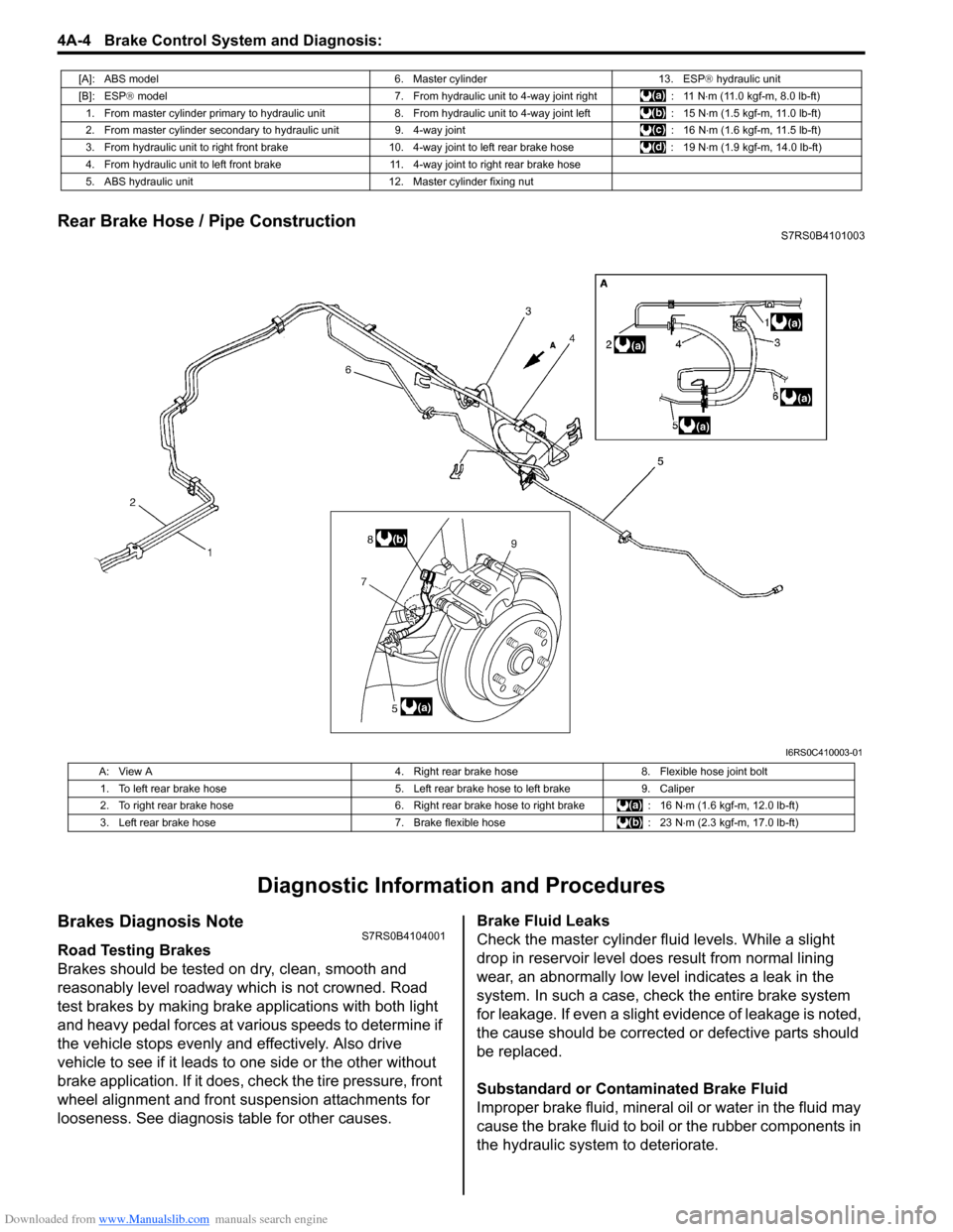
Rear Brake Hose / Pipe ConstructionS7RS0B4101003
Diagnostic Information and Procedures
Brakes Diagnosis NoteS7RS0B4104001
Road Testing Brakes
Brakes should be tested on dry, clean, smooth and
reasonably level roadway which is not crowned. Road
test brakes by making brake applications with both light
and heavy pedal forces at vari ous speeds to determine if
the vehicle stops evenly and effectively. Also drive
vehicle to see if it leads to one side or the other without
brake application. If it does, check the tire pressure, front
wheel alignment and front suspension attachments for
looseness. See diagnosis table for other causes. Brake Fluid Leaks
Check the master cylinder fl
uid levels. While a slight
drop in reservoir level does result from normal lining
wear, an abnormally low leve l indicates a leak in the
system. In such a case, chec k the entire brake system
for leakage. If even a slight ev idence of leakage is noted,
the cause should be corrected or defective parts should
be replaced.
Substandard or Contaminated Brake Fluid
Improper brake fluid, mineral oil or water in the fluid may
cause the brake fluid to boil or the rubber components in
the hydraulic system to deteriorate.
[A]: ABS model 6. Master cylinder13. ESP® hydraulic unit
[B]: ESP ® model 7. From hydraulic unit to 4-way joint right : 11 N⋅m (11.0 kgf-m, 8.0 lb-ft)
1. From master cylinder primary to hydraulic unit 8. From hydraulic unit to 4-way joint left: 15 N⋅m (1.5 kgf-m, 11.0 lb-ft)
2. From master cylinder secondary to hydraulic unit 9. 4-way joint: 16 N⋅m (1.6 kgf-m, 11.5 lb-ft)
3. From hydraulic unit to right front brake 10.4-way joint to left rear brake hose : 19 N⋅m (1.9 kgf-m, 14.0 lb-ft)
4. From hydraulic unit to left front brake 11. 4-way joint to right rear brake hose
5. ABS hydraulic unit 12. Master cylinder fixing nut
I6RS0C410003-01
A: View A4. Right rear brake hose8. Flexible hose joint bolt
1. To left rear brake hose 5. Left rear brake hose to left brake9. Caliper
2. To right rear brake hose 6. Right rear brake hose to right brake: 16 N⋅m (1.6 kgf-m, 12.0 lb-ft)
3. Left rear brake hose 7. Brake flexible hose: 23 N⋅m (2.3 kgf-m, 17.0 lb-ft)