air con test SUZUKI SWIFT 2005 2.G Service Workshop Manual
[x] Cancel search | Manufacturer: SUZUKI, Model Year: 2005, Model line: SWIFT, Model: SUZUKI SWIFT 2005 2.GPages: 1496, PDF Size: 34.44 MB
Page 1318 of 1496
Downloaded from www.Manualslib.com manuals search engine 9D-1 Wipers / Washers:
Body, Cab and Accessories
Wipers / Washers
Diagnostic Information and Procedures
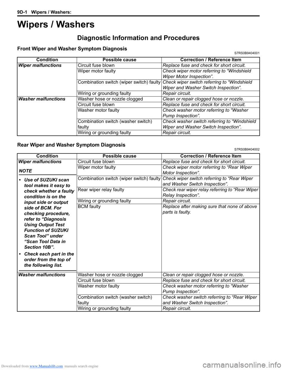
Front Wiper and Washer Symptom DiagnosisS7RS0B9404001
Rear Wiper and Washer Symptom DiagnosisS7RS0B9404002
ConditionPossible cause Correction / Reference Item
Wiper malfunctions Circuit fuse blown Replace fuse and check for short circuit.
Wiper motor faulty Check wiper motor referring to “Windshield
Wiper Motor Inspection”.
Combination switch (wiper switch) faulty Check wiper switch referring to “Windshield
Wiper and Washer Switch Inspection”.
Wiring or grounding faulty Repair circuit.
Washer malfunctions Washer hose or nozzle clogged Clean or repair clogged hose or nozzle.
Circuit fuse blown Replace fuse and check for short circuit.
Washer motor faulty Check washer motor referring to “Washer
Pump Inspection”.
Combination switch (washer switch)
faulty Check washer switch referring to “Windshield
Wiper and Washer Switch Inspection”.
Wiring or grounding faulty Repair circuit.
ConditionPossible cause Correction / Reference Item
Wiper malfunctions
NOTE
• Use of SUZUKI scan tool makes it easy to
check whether a faulty
condition is on the
input side or output
side of BCM. For
checking procedure,
refer to “Diagnosis
Using Output Test
Function of SUZUKI
Scan Tool” under
“Scan Tool Data in
Section 10B”.
• Check each part in the order from the top of
the following list.
Circuit fuse blown Replace fuse and check for short circuit.
Wiper motor faulty Check wiper motor referring to “Rear Wiper
Motor Inspection”.
Combination switch (wiper switch) faulty Check wiper switch referring to “Rear Wiper
and Washer Switch Inspection”.
Rear wiper relay faulty Check rear wiper relay referring to “Rear Wiper
Relay Inspection”.
Wiring or grounding faulty Repair circuit.
BCM faulty Replace after making sure that none of above
parts is faulty.
Washer malfunctions Washer hose or nozzle clogged Clean or repair clogged hose or nozzle.
Circuit fuse blown Replace fuse and check for short circuit.
Washer motor faulty Check washer motor referring to “Washer
Pump Inspection”.
Combination switch (washer switch)
faulty Check washer switch referring to “Rear Wiper
and Washer Switch Inspection”.
Wiring or grounding faulty Repair circuit.
Page 1329 of 1496
Downloaded from www.Manualslib.com manuals search engine Glass / Windows / Mirrors: 9E-2
• Eyeleteer
• Piano string
• Windshield knife
• Brush for primer application (2 pcs)
•Knife
• Rubber sucker grip
• Sealant gun (for filling adhesive)
• Putty spatula (for correcting adhered parts)
Diagnostic Information and Procedures
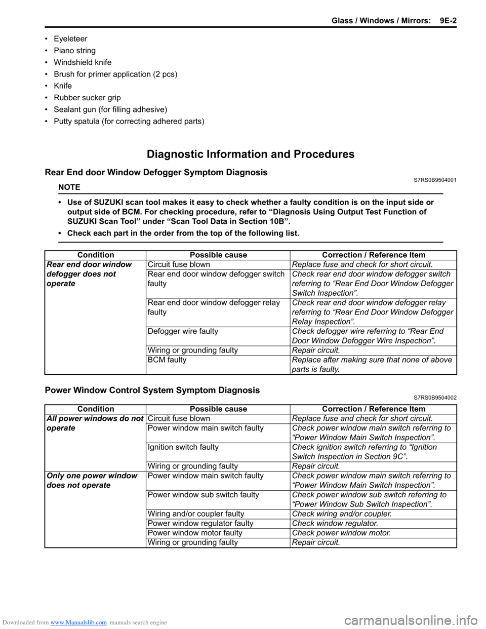
Rear End door Window Defogger Symptom DiagnosisS7RS0B9504001
NOTE
• Use of SUZUKI scan tool makes it easy to check whether a faulty condition is on the input side or
output side of BCM. For checking procedure, re fer to “Diagnosis Using Output Test Function of
SUZUKI Scan Tool” under “Scan Tool Data in Section 10B”.
• Check each part in the order from the top of the following list.
Power Window Control System Symptom DiagnosisS7RS0B9504002
Condition Possible cause Correction / Reference Item
Rear end door window
defogger does not
operate Circuit fuse blown
Replace fuse and check for short circuit.
Rear end door window defogger switch
faulty Check rear end door window defogger switch
referring to “Rear End Door Window Defogger
Switch Inspection”.
Rear end door window defogger relay
faulty Check rear end door window defogger relay
referring to “Rear End Door Window Defogger
Relay Inspection”.
Defogger wire faulty Check defogger wire referring to “Rear End
Door Window Defogger Wire Inspection”.
Wiring or grounding faulty Repair circuit.
BCM faulty Replace after making sure that none of above
parts is faulty.
ConditionPossible cause Correction / Reference Item
All power windows do not
operate Circuit fuse blown
Replace fuse and check for short circuit.
Power window main switch faulty Check power window main switch referring to
“Power Window Main Switch Inspection”.
Ignition switch faulty Check ignition switch referring to “Ignition
Switch Inspection in Section 9C”.
Wiring or grounding faulty Repair circuit.
Only one power window
does not operate Power window main switch faulty
Check power window main switch referring to
“Power Window Main Switch Inspection”.
Power window sub switch faulty Check power window sub switch referring to
“Power Window Sub Switch Inspection”.
Wiring and/or coupler faulty Check wiring and/or coupler.
Power window regulator faulty Check window regulator.
Power window motor faulty Check power window motor.
Wiring or grounding faulty Repair circuit.
Page 1330 of 1496
Downloaded from www.Manualslib.com manuals search engine 9E-3 Glass / Windows / Mirrors:
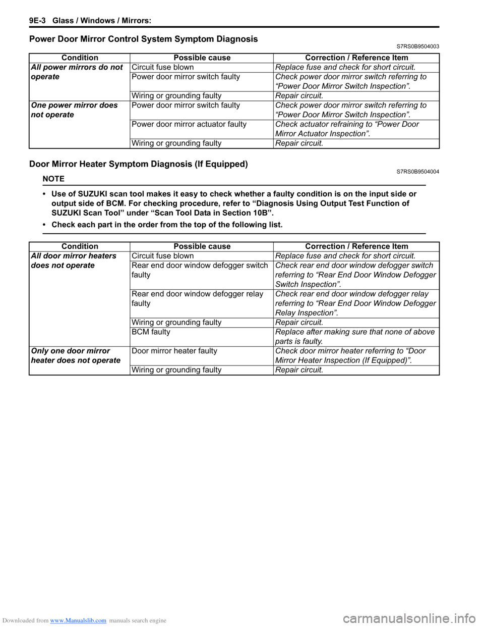
Power Door Mirror Control System Symptom DiagnosisS7RS0B9504003
Door Mirror Heater Symptom Diagnosis (If Equipped)S7RS0B9504004
NOTE
• Use of SUZUKI scan tool makes it easy to check whether a faulty condition is on the input side or
output side of BCM. For checking procedure, re fer to “Diagnosis Using Output Test Function of
SUZUKI Scan Tool” under “Scan Tool Data in Section 10B”.
• Check each part in the order from the top of the following list.
Condition Possible cause Correction / Reference Item
All power mirrors do not
operate Circuit fuse blown
Replace fuse and check for short circuit.
Power door mirror switch faulty Check power door mirror switch referring to
“Power Door Mirror Switch Inspection”.
Wiring or grounding faulty Repair circuit.
One power mirror does
not operate Power door mirror switch faulty
Check power door mirror switch referring to
“Power Door Mirror Switch Inspection”.
Power door mirror actuator faulty Check actuator refraining to “Power Door
Mirror Actuator Inspection”.
Wiring or grounding faulty Repair circuit.
ConditionPossible cause Correction / Reference Item
All door mirror heaters
does not operate Circuit fuse blown
Replace fuse and check for short circuit.
Rear end door window defogger switch
faulty Check rear end door window defogger switch
referring to “Rear End Door Window Defogger
Switch Inspection”.
Rear end door window defogger relay
faulty Check rear end door window defogger relay
referring to “Rear End Door Window Defogger
Relay Inspection”.
Wiring or grounding faulty Repair circuit.
BCM faulty Replace after making sure that none of above
parts is faulty.
Only one door mirror
heater does not operate Door mirror heater faulty
Check door mirror heater referring to “Door
Mirror Heater Inspection (If Equipped)”.
Wiring or grounding faulty Repair circuit.
Page 1342 of 1496
Downloaded from www.Manualslib.com manuals search engine 9E-15 Glass / Windows / Mirrors:
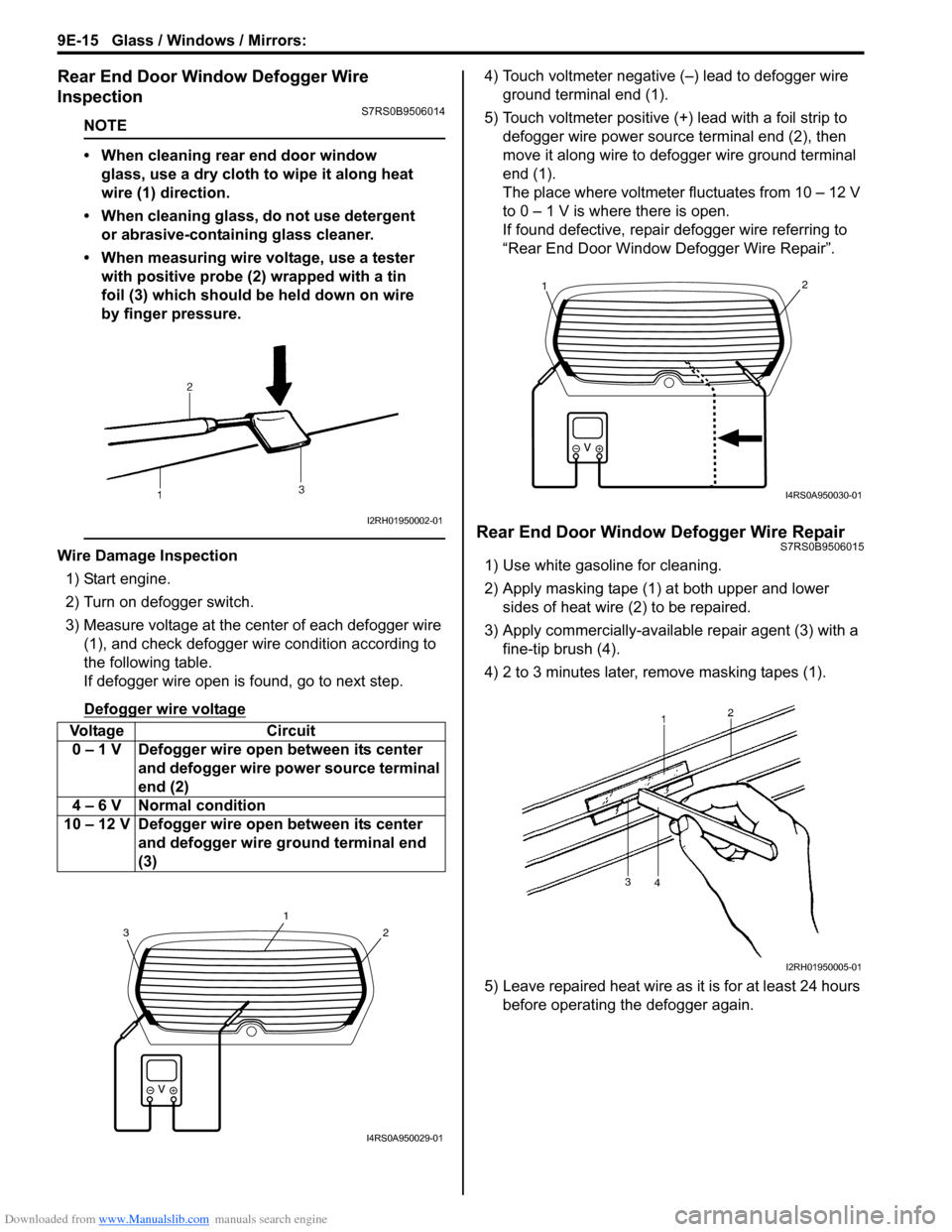
Rear End Door Window Defogger Wire
Inspection
S7RS0B9506014
NOTE
• When cleaning rear end door window glass, use a dry cloth to wipe it along heat
wire (1) direction.
• When cleaning glass, do not use detergent or abrasive-containing glass cleaner.
• When measuring wire voltage, use a tester with positive probe (2) wrapped with a tin
foil (3) which should be held down on wire
by finger pressure.
Wire Damage Inspection
1) Start engine.
2) Turn on defogger switch.
3) Measure voltage at the center of each defogger wire (1), and check defogger wire condition according to
the following table.
If defogger wire open is found, go to next step.
Defogger wire voltage
4) Touch voltmeter negative (–) lead to defogger wire ground terminal end (1).
5) Touch voltmeter positive (+) lead with a foil strip to defogger wire power source terminal end (2), then
move it along wire to defogger wire ground terminal
end (1).
The place where voltmeter fluctuates from 10 – 12 V
to 0 – 1 V is where there is open.
If found defective, repair defogger wire referring to
“Rear End Door Window Defogger Wire Repair”.
Rear End Door Window Defogger Wire RepairS7RS0B9506015
1) Use white gasoline for cleaning.
2) Apply masking tape (1) at both upper and lower sides of heat wire (2) to be repaired.
3) Apply commercially-available repair agent (3) with a fine-tip brush (4).
4) 2 to 3 minutes later, remove masking tapes (1).
5) Leave repaired heat wire as it is for at least 24 hours before operating the defogger again.
Voltage Circuit
0 – 1 V Defogger wire open between its center and defogger wire power source terminal
end (2)
4 – 6 V Normal condition
10 – 12 V Defogger wire open between its center and defogger wire ground terminal end
(3)
I2RH01950002-01
2
1
3
I4RS0A950029-01
21
I4RS0A950030-01
I2RH01950005-01
Page 1349 of 1496
Downloaded from www.Manualslib.com manuals search engine Security and Locks: 9F-3
Diagnostic Information and Procedures
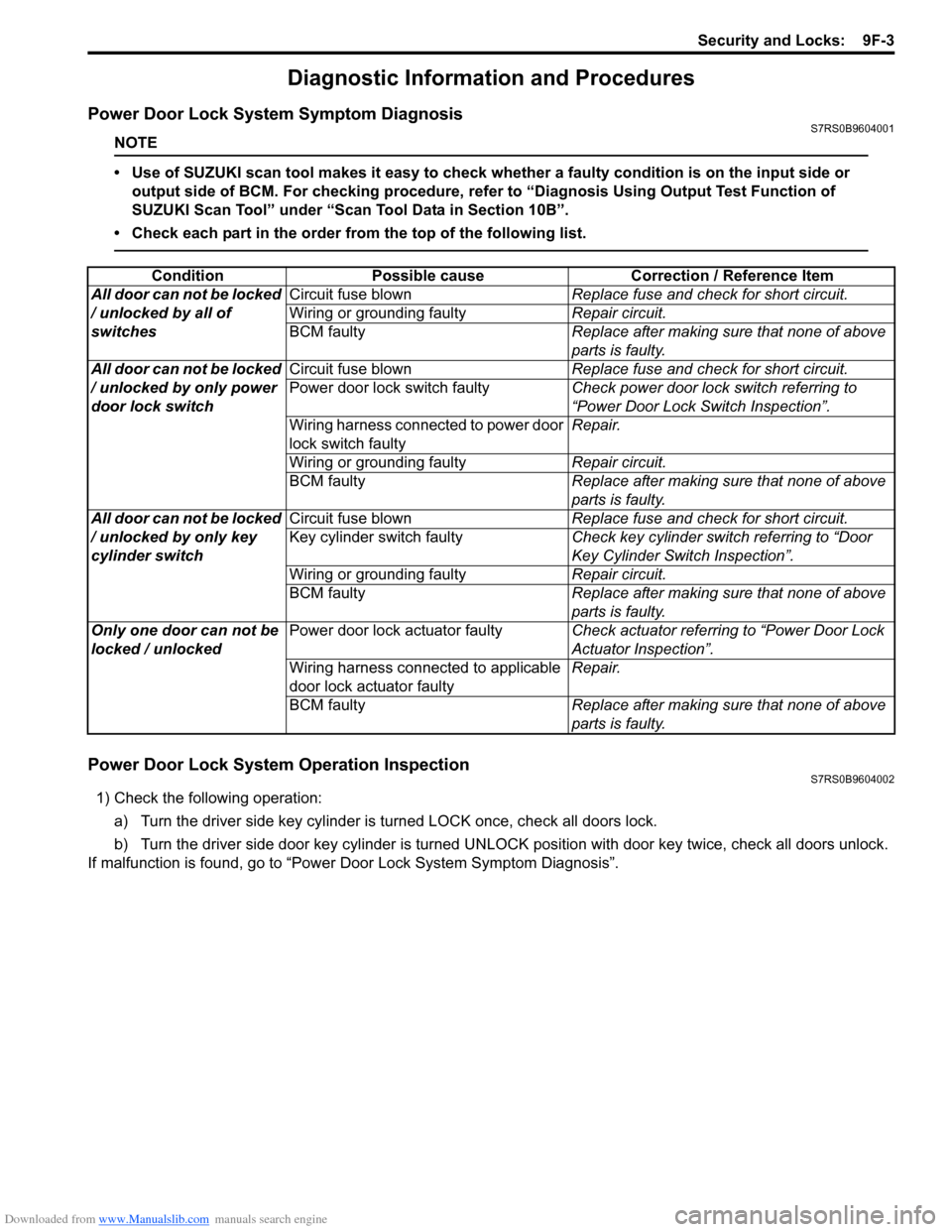
Power Door Lock System Symptom DiagnosisS7RS0B9604001
NOTE
• Use of SUZUKI scan tool makes it easy to check whether a faulty condition is on the input side or
output side of BCM. For checking procedure, re fer to “Diagnosis Using Output Test Function of
SUZUKI Scan Tool” under “Scan Tool Data in Section 10B”.
• Check each part in the order from the top of the following list.
Power Door Lock System Operation InspectionS7RS0B9604002
1) Check the following operation:
a) Turn the driver side key cylinder is turned LOCK once, check all doors lock.
b) Turn the driver side door key cylinder is turned UNLOC K position with door key twice, check all doors unlock.
If malfunction is found, go to “Power Door Lock System Symptom Diagnosis”.
Condition Possible cause Correction / Reference Item
All door can not be locked
/ unlocked by all of
switches Circuit fuse blown
Replace fuse and check for short circuit.
Wiring or grounding faulty Repair circuit.
BCM faulty Replace after making sure that none of above
parts is faulty.
All door can not be locked
/ unlocked by only power
door lock switch Circuit fuse blown
Replace fuse and check for short circuit.
Power door lock switch faulty Check power door lock switch referring to
“Power Door Lock Switch Inspection”.
Wiring harness connected to power door
lock switch faulty Repair.
Wiring or grounding faulty Repair circuit.
BCM faulty Replace after making sure that none of above
parts is faulty.
All door can not be locked
/ unlocked by only key
cylinder switch Circuit fuse blown
Replace fuse and check for short circuit.
Key cylinder switch faulty Check key cylinder switch referring to “Door
Key Cylinder Switch Inspection”.
Wiring or grounding faulty Repair circuit.
BCM faulty Replace after making sure that none of above
parts is faulty.
Only one door can not be
locked / unlocked Power door lock actuator faulty
Check actuator referring to “Power Door Lock
Actuator Inspection”.
Wiring harness connected to applicable
door lock actuator faulty Repair.
BCM faulty Replace after making sure that none of above
parts is faulty.
Page 1351 of 1496
Downloaded from www.Manualslib.com manuals search engine Security and Locks: 9F-5
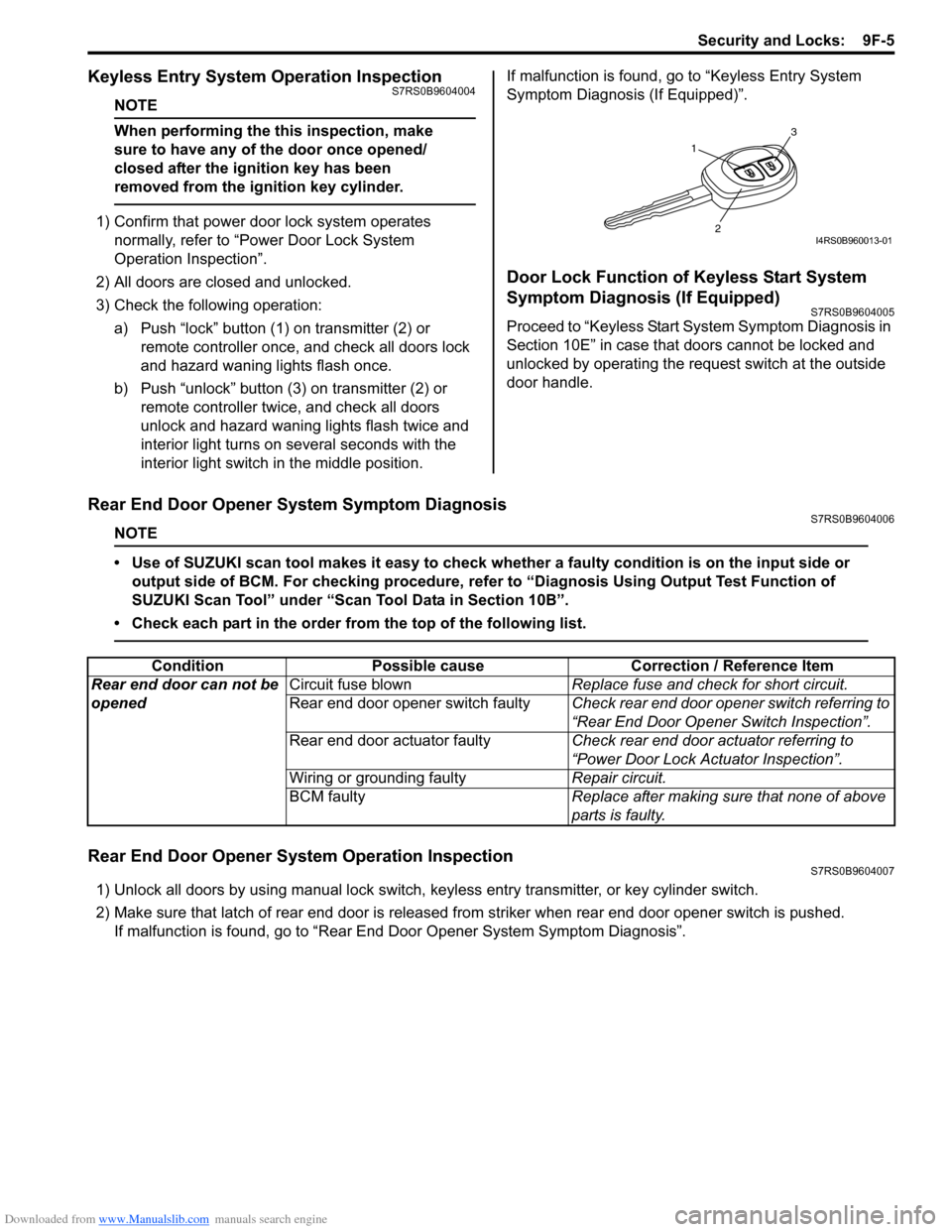
Keyless Entry System Operation InspectionS7RS0B9604004
NOTE
When performing the this inspection, make
sure to have any of the door once opened/
closed after the ignition key has been
removed from the ignition key cylinder.
1) Confirm that power door lock system operates normally, refer to “Power Door Lock System
Operation Inspection”.
2) All doors are closed and unlocked.
3) Check the following operation: a) Push “lock” button (1 ) on transmitter (2) or
remote controller once, and check all doors lock
and hazard waning lights flash once.
b) Push “unlock” button (3) on transmitter (2) or remote controller twice, and check all doors
unlock and hazard waning lights flash twice and
interior light turns on several seconds with the
interior light switch in the middle position. If malfunction is found, go to “Keyless Entry System
Symptom Diagnosis (If Equipped)”.
Door Lock Function of Keyless Start System
Symptom Diagnosis (If Equipped)
S7RS0B9604005
Proceed to “Keyless Start System Symptom Diagnosis in
Section 10E” in case that doors cannot be locked and
unlocked by operating the request switch at the outside
door handle.
Rear End Door Opener System Symptom DiagnosisS7RS0B9604006
NOTE
• Use of SUZUKI scan tool makes it easy to check wh
ether a faulty condition is on the input side or
output side of BCM. For checking procedure, re fer to “Diagnosis Using Output Test Function of
SUZUKI Scan Tool” under “Scan Tool Data in Section 10B”.
• Check each part in the order from the top of the following list.
Rear End Door Opener System Operation InspectionS7RS0B9604007
1) Unlock all doors by using manu al lock switch, keyless entry transmitter, or key cylinder switch.
2) Make sure that latch of rear end door is released from striker when rear end door opener switch is pushed. If malfunction is found, go to “Rear End Door Opener System Symptom Diagnosis”.
1
3
2I4RS0B960013-01
ConditionPossible cause Correction / Reference Item
Rear end door can not be
opened Circuit fuse blown
Replace fuse and check for short circuit.
Rear end door opener switch faulty Check rear end door opener switch referring to
“Rear End Door Opener Switch Inspection”.
Rear end door actuator faulty Check rear end door actuator referring to
“Power Door Lock Actuator Inspection”.
Wiring or grounding faulty Repair circuit.
BCM faulty Replace after making sure that none of above
parts is faulty.
Page 1389 of 1496
Downloaded from www.Manualslib.com manuals search engine Paint / Coatings: 9L-2
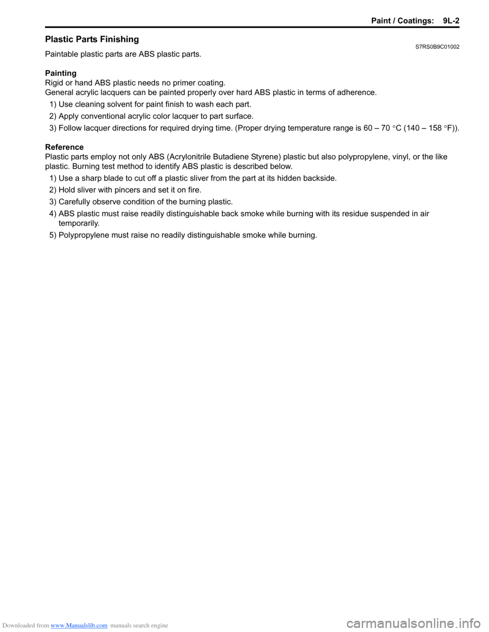
Plastic Parts FinishingS7RS0B9C01002
Paintable plastic parts are ABS plastic parts.
Painting
Rigid or hand ABS plastic needs no primer coating.
General acrylic lacquers can be painted properly over hard ABS plastic in terms of adherence.
1) Use cleaning solvent for paint finish to wash each part.
2) Apply conventional acrylic color lacquer to part surface.
3) Follow lacquer directions for required drying time. (Proper drying temperature range is 60 – 70 °C (140 – 158 ° F)).
Reference
Plastic parts employ not only ABS (Acrylonitrile Butadiene Styrene) plastic but also polypro pylene, vinyl, or the like
plastic. Burning test method to iden tify ABS plastic is described below.
1) Use a sharp blade to cut off a plastic sliver from the part at its hidden backside.
2) Hold sliver with pincer s and set it on fire.
3) Carefully observe condition of the burning plastic.
4) ABS plastic must raise readily dist inguishable back smoke while burning with its residue suspended in air
temporarily.
5) Polypropylene must raise no readily distinguishable smoke while burning.
Page 1413 of 1496
Downloaded from www.Manualslib.com manuals search engine Body Electrical Control System: 10B-10
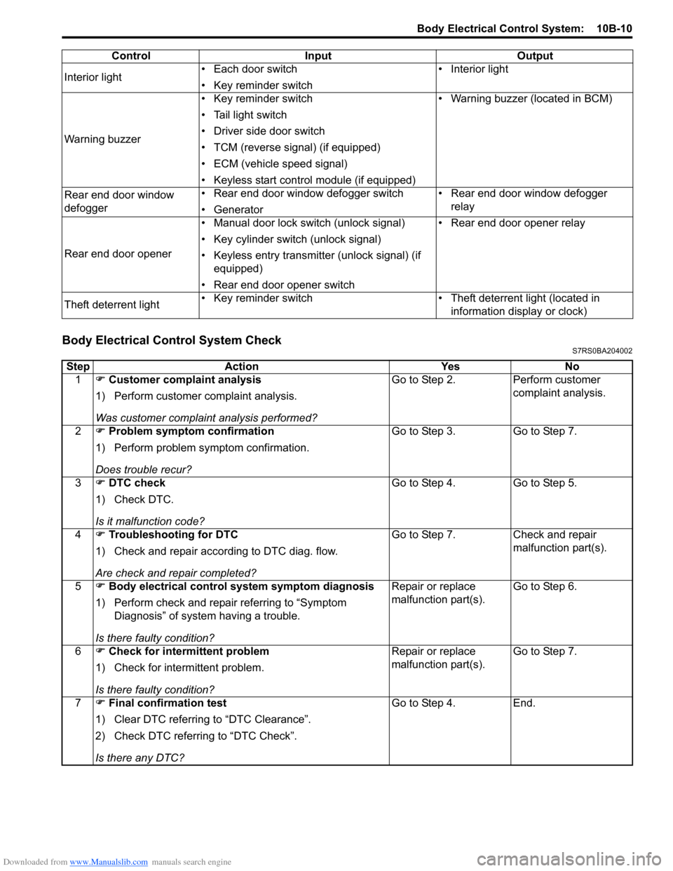
Body Electrical Control System CheckS7RS0BA204002
Interior light• Each door switch
• Key reminder switch • Interior light
Warning buzzer • Key reminder switch
• Tail light switch
• Driver side door switch
• TCM (reverse signal) (if equipped)
• ECM (vehicle speed signal)
• Keyless start control module (if equipped) • Warning buzzer (located in BCM)
Rear end door window
defogger • Rear end door window defogger switch
• Generator • Rear end door window defogger
relay
Rear end door opener • Manual door lock switch (unlock signal)
• Key cylinder switch (unlock signal)
• Keyless entry transmitter (unlock signal) (if
equipped)
• Rear end door opener switch • Rear end door opener relay
Theft deterrent light • Key reminder switch • Theft deterrent light (located in
information display or clock)
Control Input Output
Step
Action YesNo
1 �) Customer complaint analysis
1) Perform customer complaint analysis.
Was customer complaint analysis performed? Go to Step 2.
Perform customer
complaint analysis.
2 �) Problem symptom confirmation
1) Perform problem symptom confirmation.
Does trouble recur? Go to Step 3.
Go to Step 7.
3 �) DTC check
1) Check DTC.
Is it malfunction code? Go to Step 4.
Go to Step 5.
4 �) Troubleshooting for DTC
1) Check and repair according to DTC diag. flow.
Are check and repair completed? Go to Step 7.
Check and repair
malfunction part(s).
5 �) Body electrical control system symptom diagnosis
1) Perform check and repair referring to “Symptom Diagnosis” of system having a trouble.
Is there faulty condition? Repair or replace
malfunction part(s).
Go to Step 6.
6 �) Check for intermittent problem
1) Check for interm ittent problem.
Is there faulty condition? Repair or replace
malfunction part(s).
Go to Step 7.
7 �) Final confirmation test
1) Clear DTC referring to “DTC Clearance”.
2) Check DTC referring to “DTC Check”.
Is there any DTC? Go to Step 4.
End.
Page 1414 of 1496
Downloaded from www.Manualslib.com manuals search engine 10B-11 Body Electrical Control System:
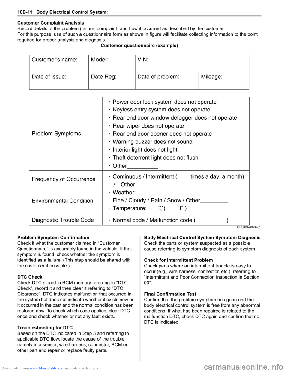
Customer Complaint Analysis
Record details of the problem (failure, complaint) and how it occurred as described by the customer.
For this purpose, use of such a questionnaire form as shown in figure will facilitate collectin g information to the point
required for proper analysis and diagnosis. Customer questionnaire (example)
Problem Symptom Confirmation
Check if what the custom er claimed in “Customer
Questionnaire” is accurately f ound in the vehicle. If that
symptom is found, check whether the symptom is
identified as a failure. (This step should be shared with
the customer if possible.)
DTC Check
Check DTC stored in BCM me mory referring to “DTC
Check”, record it and then clear it referring to “DTC
Clearance”. DTC indicates malfunction that occurred in
the system but does not indicate whether it exists now or
it occurred in the past and the normal condition has been
restored now. To check which case applies, clear DTC
once and check whether or not any fault exists.
Troubleshooting for DTC
Based on the DTC indicated in Step 3 and referring to
applicable DTC flow, locate the cause of the trouble,
namely in a sensor, wire harness, connector, BCM or
other part and repair or replace faulty parts. Body Electrical Control System Symptom Diagnosis
Check the parts or system
suspected as a possible
cause referring to symptom diagnosis of each system.
Check for Intermi ttent Problem
Check parts where an intermit tent trouble is easy to
occur (e.g., wire harness, connector, etc.), referring to
“Intermittent and Poor Connec tion Inspection in Section
00”.
Final Confirmation Test
Confirm that the problem symptom has gone and the
body electrical control system is free from any abnormal
conditions. If what has been repaired is related to the
malfunction DTC, check DTC again and confirm that no
DTC is indicated.
Customers name:
Model:
VIN:
Date of issue:
Date Reg:
Date of problem:
Mileage:
Problem Symptoms
Power door lock system does not operate
Keyless entry system does not operate
Rear end door window defogger does not operate
Rear wiper does not operate
Rear end door opener does not operate
Other
Frequency of Occurrence
Continuous / Intermittent ( times a day, a month)
/ Other
Environmental Condition
Weather:
Fine / Cloudy / Rain / Snow / Other
Temperature: (F )
Diagnostic Trouble Code Normal code / Malfunction code ( )
Warning buzzer does not sound
Interior light does not light
Theft deterrent light does not flush
I5RS0DA20006-01
Page 1416 of 1496
Downloaded from www.Manualslib.com manuals search engine 10B-13 Body Electrical Control System:
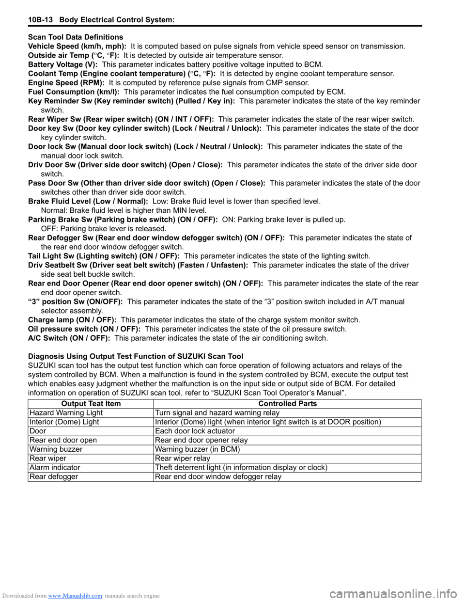
Scan Tool Data Definitions
Vehicle Speed (km/h, mph): It is computed based on pulse signals from vehicle speed sensor on transmission.
Outside air Temp ( °C, °F): It is detected by outside air temperature sensor.
Battery Voltage (V): This parameter indicates battery po sitive voltage inputted to BCM.
Coolant Temp (Engine coolant temperature) ( °C, °F): It is detected by engine coolant temperature sensor.
Engine Speed (RPM): It is computed by reference pulse signals from CMP sensor.
Fuel Consumption (km/l): This parameter indicates the fuel consumption computed by ECM.
Key Reminder Sw (Key reminder switch) (Pulled / Key in): This parameter indicates the state of the key reminder
switch.
Rear Wiper Sw (Rear wiper switch) (ON / INT / OFF): This parameter indicates the state of the rear wiper switch.
Door key Sw (Door key cylinder switch) (Lock / Neutral / Unlock): This parameter indicates the state of the door
key cylinder switch.
Door lock Sw (Manual door lock switch) (Lock / Neutral / Unlock): This parameter indicates the state of the
manual door lock switch.
Driv Door Sw (Driver side d oor switch) (Open / Close): This parameter indicates the state of the driver side door
switch.
Pass Door Sw (Other than driver side door switch) (Open / Close): This parameter indicates the state of the door
switches other than driver side door switch.
Brake Fluid Level (Low / Normal): Low: Brake fluid level is lower than specified level.
Normal: Brake fluid level is higher than MIN level.
Parking Brake Sw (Parking brake switch) (ON / OFF): ON: Parking brake lever is pulled up.
OFF: Parking brake lever is released.
Rear Defogger Sw (Rear end door window defogger switch) (ON / OFF): This parameter indicates the state of
the rear end door window defogger switch.
Tail Light Sw (Lighting switch) (ON / OFF): This parameter indicates the state of the lighting switch.
Driv Seatbelt Sw (Driver seat belt switch) (Fasten / Unfasten): This parameter indicates the state of the driver
side seat belt buckle switch.
Rear end Door Opener (Rear end door opener switch) (ON / OFF): This parameter indicates the state of the rear
end door opener switch.
“3” position Sw (ON/OFF): This parameter indicates the state of the “3 ” position switch included in A/T manual
selector assembly.
Charge lamp (ON / OFF): This parameter indicates the state of the charge system monitor switch.
Oil pressure switch (ON / OFF): This parameter indicates the state of the oil pressure switch.
A/C Switch (ON / OFF): This parameter indicates the state of the air conditioning switch.
Diagnosis Using Output Test Function of SUZUKI Scan Tool
SUZUKI scan tool has the output test function which can force operation of following actuators and relays of the
system controlled by BCM. When a malf unction is found in the system controlled by BCM, execute the output test
which enables easy judgment whether the malfunction is on the input side or output side of BCM. For detailed
information on operation of SUZUKI scan tool, refer to “SUZUKI Scan Tool Operator’s Manual”.
Output Teat Item Controlled Parts
Hazard Warning Light Turn signal and hazard warning relay
Interior (Dome) Light Interior (Dome) light (wh en interior light switch is at DOOR position)
Door Each door lock actuator
Rear end door open Rear end door opener relay
Warning buzzer Warning buzzer (in BCM)
Rear wiper Rear wiper relay
Alarm indicator Theft deterrent light (in information display or clock)
Rear defogger Rear end door window defogger relay