O2 sensor SUZUKI SWIFT 2005 2.G Service Workshop Manual
[x] Cancel search | Manufacturer: SUZUKI, Model Year: 2005, Model line: SWIFT, Model: SUZUKI SWIFT 2005 2.GPages: 1496, PDF Size: 34.44 MB
Page 261 of 1496
Downloaded from www.Manualslib.com manuals search engine Engine General Information and Diagnosis: 1A-211
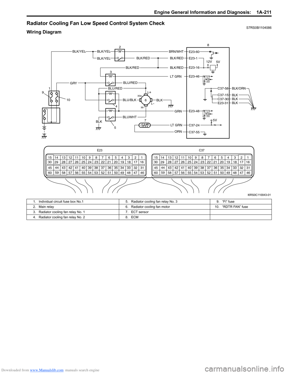
Radiator Cooling Fan Low Speed Control System CheckS7RS0B1104086
Wiring Diagram
E23C37
34
1819
567
1011
17
20
47 46
495051
2122
52 16
25 9
24
14
29
55
57 54 53
59
60 58 2
262728
15
30
56 4832 31
34353637
40
42 39 38
44
45 43 41 331
1213
238
34
1819
567
1011
17
20
47 46
495051
2122
52 16
25 9
24
14
29
55
57 54 53
59
60 58 2
262728
15
30
56 4832 31
34353637
40
42 39 38
44
45 43 41 331
1213
238
BLK/REDBLK/RED
BLK/YELBLK/YEL
BLK/YEL
BRN/WHT
12V
5V5V
2
8
E23-1
E23-60
C37-58
C37-15 C37-30
BLK/ORN
BLKBLKE23-31 BLK
BLK/RED
LT GRN
BLK/REDE23-16
E23-46
L+
L–
H–
H
+
BLU/RED
BLK
BLUWHTBLK
BLU/BLK
BLU/RED
4
GRN
GRY
E23-48
LT GRN
ORN
C37-24
C37-55
35
6
7
10
9
1
I6RS0C110043-01
1. Individual circuit fuse box No.1
5. Radiator cooling fan relay No. 3 9. “FI” fuse
2. Main relay 6. Radiator cooling fan motor10. “RDTR FAN” fuse
3. Radiator cooling fan relay No. 1 7. ECT sensor
4. Radiator cooling fan relay No. 2 8. ECM
Page 262 of 1496
Downloaded from www.Manualslib.com manuals search engine 1A-212 Engine General Information and Diagnosis:
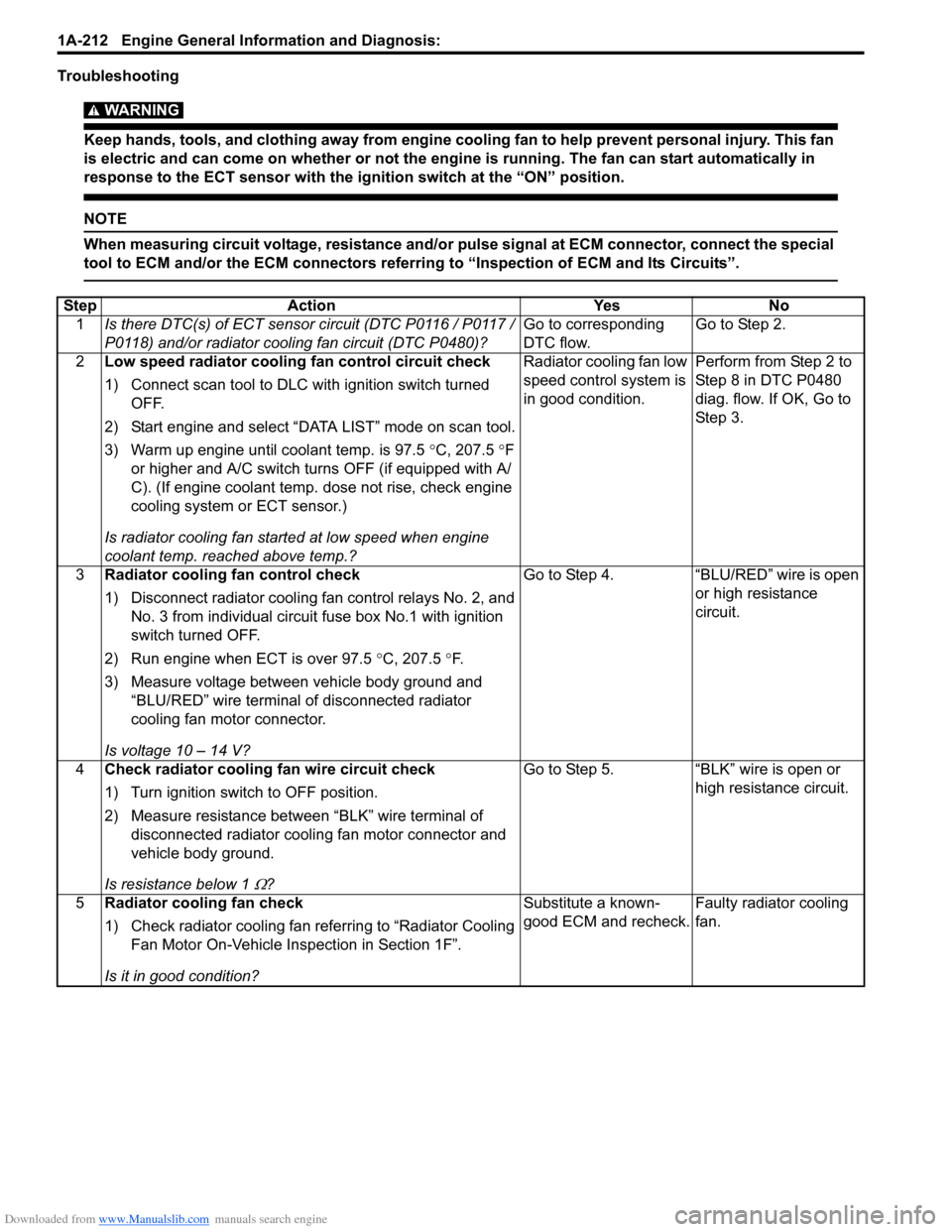
Troubleshooting
WARNING!
Keep hands, tools, and clothing away from engine cooling fan to help prevent personal injury. This fan
is electric and can come on whether or not the engi ne is running. The fan can start automatically in
response to the ECT sensor with the ig nition switch at the “ON” position.
NOTE
When measuring circuit voltage, resistance and/or pulse signal at ECM connector, connect the special
tool to ECM and/or the ECM connectors referri ng to “Inspection of ECM and Its Circuits”.
StepAction YesNo
1 Is there DTC(s) of ECT sensor circuit (DTC P0116 / P0117 /
P0118) and/or radiator cooling fan circuit (DTC P0480)? Go to corresponding
DTC flow.Go to Step 2.
2 Low speed radiator cooling fan control circuit check
1) Connect scan tool to DLC with ignition switch turned
OFF.
2) Start engine and select “DATA LIST” mode on scan tool.
3) Warm up engine until coolant temp. is 97.5 °C, 207.5 °F
or higher and A/C switch turns OFF (if equipped with A/
C). (If engine coolant temp. dose not rise, check engine
cooling system or ECT sensor.)
Is radiator cooling fan started at low speed when engine
coolant temp. reached above temp.? Radiator cooling fan low
speed control system is
in good condition.
Perform from Step 2 to
Step 8 in DTC P0480
diag. flow. If OK, Go to
Ste p 3.
3 Radiator cooling fan control check
1) Disconnect radiator cooling fan control relays No. 2, and
No. 3 from individual circuit fuse box No.1 with ignition
switch turned OFF.
2) Run engine when ECT is over 97.5 °C, 207.5 °F.
3) Measure voltage between vehicle body ground and “BLU/RED” wire terminal of disconnected radiator
cooling fan motor connector.
Is voltage 10 – 14 V? Go to Step 4.
“BLU/RED” wire is open
or high resistance
circuit.
4 Check radiator cooling fan wire circuit check
1) Turn ignition switch to OFF position.
2) Measure resistance between “BLK” wire terminal of
disconnected radiator coolin g fan motor connector and
vehicle body ground.
Is resistance below 1
Ω? Go to Step 5. “BLK” wire is open or
high resistance circuit.
5 Radiator cooling fan check
1) Check radiator cooling fan referring to “Radiator Cooling
Fan Motor On-Vehicle Inspection in Section 1F”.
Is it in good condition? Substitute a known-
good ECM and recheck.
Faulty radiator cooling
fan.
Page 263 of 1496
Downloaded from www.Manualslib.com manuals search engine Engine General Information and Diagnosis: 1A-213
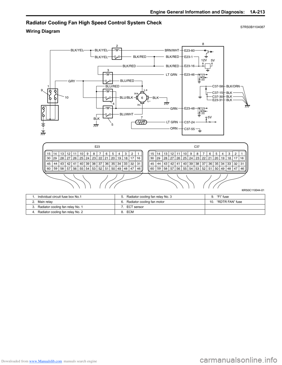
Radiator Cooling Fan High Speed Control System CheckS7RS0B1104087
Wiring Diagram
E23C37
34
1819
567
1011
17
20
47 46
495051
2122
52 16
25 9
24
14
29
55
57 54 53
59
60 58 2
262728
15
30
56 4832 31
34353637
40
42 39 38
44
45 43 41 331
1213
238
34
1819
567
1011
17
20
47 46
495051
2122
52 16
25 9
24
14
29
55
57 54 53
59
60 58 2
262728
15
30
56 4832 31
34353637
40
42 39 38
44
45 43 41 331
1213
238
BLK/REDBLK/RED
BLK/YELBLK/YEL
BLK/YEL
BRN/WHT
12V
5V5V
2
8
E23-1
E23-60
C37-58
C37-15 C37-30
BLK/ORN
BLKBLKE23-31 BLK
BLK/RED
LT GRN
BLK/REDE23-16
E23-46
L+
L–
H–
H
+
BLU/RED
BLK
BLUWHTBLK
BLU/BLK
BLU/RED
4
GRN
GRY
E23-48
LT GRN
ORN
C37-24
C37-55
35
6
7
10
9
1
I6RS0C110044-01
1. Individual circuit fuse box No.1
5. Radiator cooling fan relay No. 3 9. “FI” fuse
2. Main relay 6. Radiator cooling fan motor10. “RDTR FAN” fuse
3. Radiator cooling fan relay No. 1 7. ECT sensor
4. Radiator cooling fan relay No. 2 8. ECM
Page 264 of 1496
Downloaded from www.Manualslib.com manuals search engine 1A-214 Engine General Information and Diagnosis:
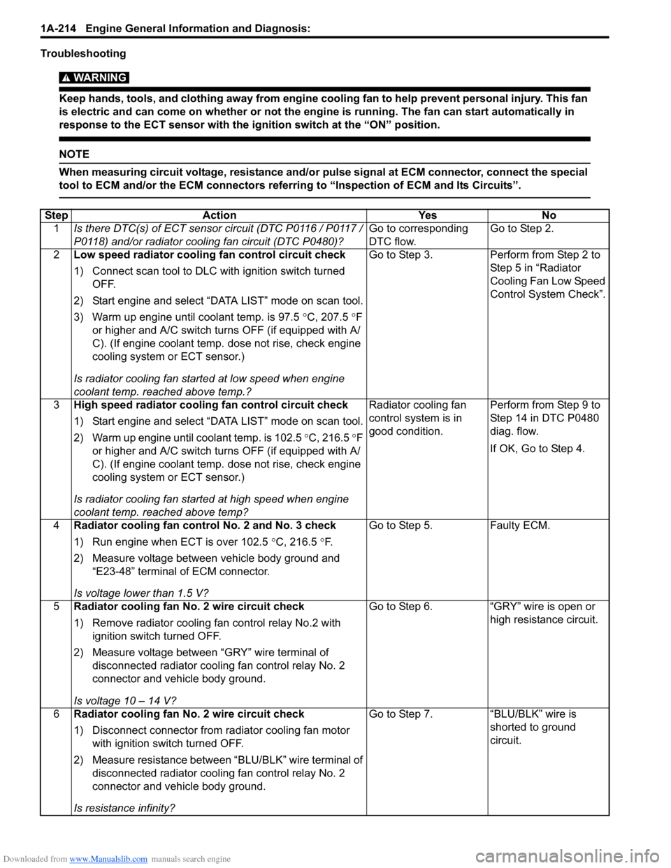
Troubleshooting
WARNING!
Keep hands, tools, and clothing away from engine cooling fan to help prevent personal injury. This fan
is electric and can come on whether or not the engi ne is running. The fan can start automatically in
response to the ECT sensor with the ig nition switch at the “ON” position.
NOTE
When measuring circuit voltage, resistance and/or pulse signal at ECM connector, connect the special
tool to ECM and/or the ECM connectors referri ng to “Inspection of ECM and Its Circuits”.
StepAction YesNo
1 Is there DTC(s) of ECT sensor circuit (DTC P0116 / P0117 /
P0118) and/or radiator cooling fan circuit (DTC P0480)? Go to corresponding
DTC flow.Go to Step 2.
2 Low speed radiator cooling fan control circuit check
1) Connect scan tool to DLC with ignition switch turned
OFF.
2) Start engine and select “DATA LIST” mode on scan tool.
3) Warm up engine until coolant temp. is 97.5 °C, 207.5 °F
or higher and A/C switch turns OFF (if equipped with A/
C). (If engine coolant temp. dose not rise, check engine
cooling system or ECT sensor.)
Is radiator cooling fan started at low speed when engine
coolant temp. reached above temp.? Go to Step 3.
Perform from Step 2 to
Step 5 in “Radiator
Cooling Fan Low Speed
Control System Check”.
3 High speed radiator cooling fan control circuit check
1) Start engine and select “DATA LIST” mode on scan tool.
2) Warm up engine until coolant temp. is 102.5 °C, 216.5 °F
or higher and A/C switch turns OFF (if equipped with A/
C). (If engine coolant temp. dose not rise, check engine
cooling system or ECT sensor.)
Is radiator cooling fan started at high speed when engine
coolant temp. reached above temp? Radiator cooling fan
control system is in
good condition.
Perform from Step 9 to
Step 14 in DTC P0480
diag. flow.
If OK, Go to Step 4.
4 Radiator cooling fan control No. 2 and No. 3 check
1) Run engine when ECT is over 102.5 °C, 216.5 °F.
2) Measure voltage between vehicle body ground and “E23-48” terminal of ECM connector.
Is voltage lower than 1.5 V? Go to Step 5.
Faulty ECM.
5 Radiator cooling fan No. 2 wire circuit check
1) Remove radiator cooling fan control relay No.2 with
ignition switch turned OFF.
2) Measure voltage between “GRY” wire terminal of disconnected radiator cooling fan control relay No. 2
connector and vehicle body ground.
Is voltage 10 – 14 V? Go to Step 6.
“GRY” wire is open or
high resistance circuit.
6 Radiator cooling fan No. 2 wire circuit check
1) Disconnect connector from radiator cooling fan motor
with ignition swit ch turned OFF.
2) Measure resistance between “BLU/BLK” wire terminal of disconnected radiator cooling fan control relay No. 2
connector and vehicle body ground.
Is resistance infinity? Go to Step 7.
“BLU/BLK” wire is
shorted to ground
circuit.
Page 274 of 1496
Downloaded from www.Manualslib.com manuals search engine 1C-2 Engine Electrical Devices:
MAP Sensor InspectionS7RS0B1306002
1) Remove air cleaner assembly.
2) Disconnect connector from MAP sensor.
3) Remove MAP sensor.
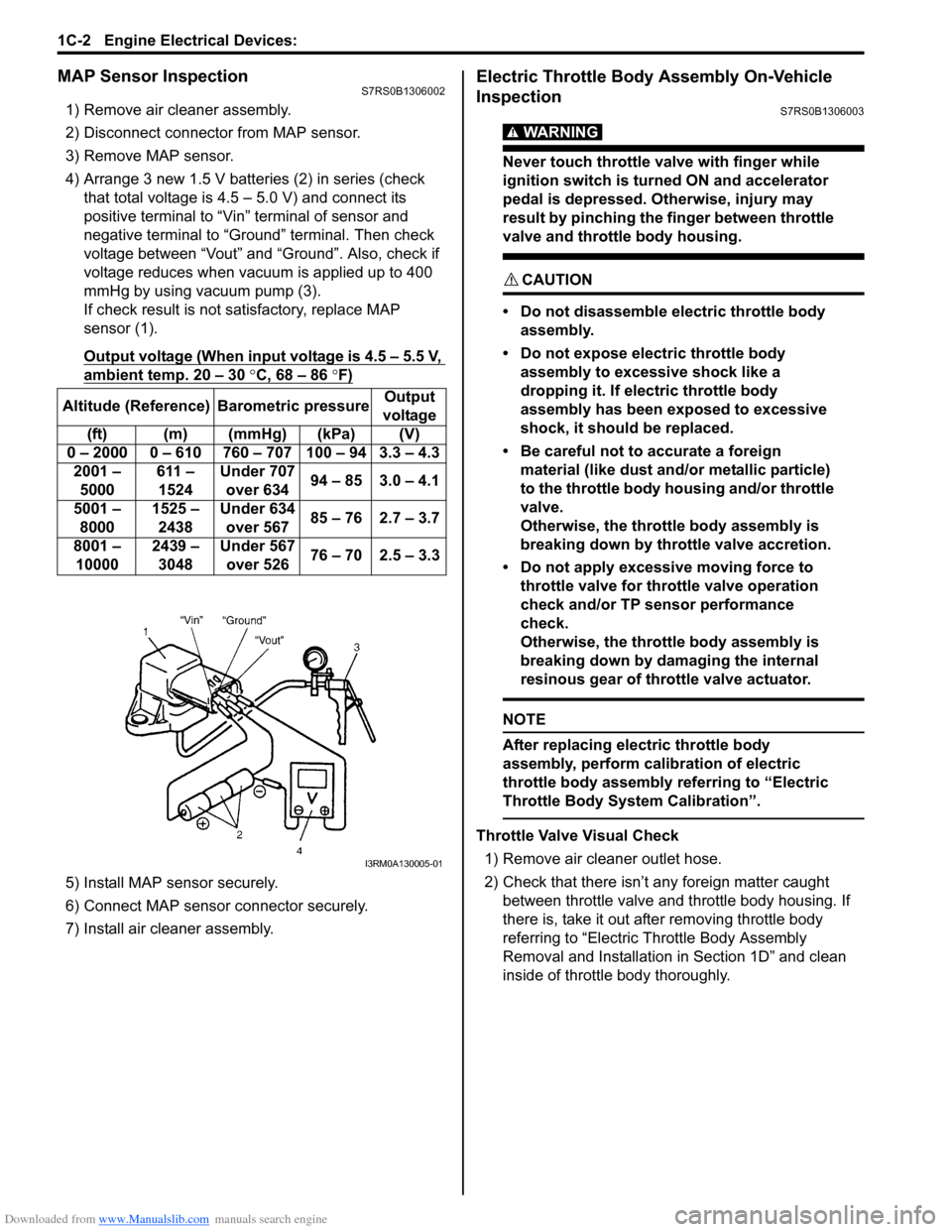
4) Arrange 3 new 1.5 V batteries (2) in series (check that total voltage is 4.5 – 5.0 V) and connect its
positive terminal to “Vin ” terminal of sensor and
negative terminal to “Ground” terminal. Then check
voltage between “Vout” and “Ground”. Also, check if
voltage reduces when vacuum is applied up to 400
mmHg by using vacuum pump (3).
If check result is not satisfactory, replace MAP
sensor (1).
Output voltage (When input voltage is 4.5 – 5.5 V,
ambient temp. 20 – 30 °C, 68 – 86 °F)
5) Install MAP sensor securely.
6) Connect MAP sensor connector securely.
7) Install air cleaner assembly.
Electric Throttle Body Assembly On-Vehicle
Inspection
S7RS0B1306003
WARNING!
Never touch throttle valve with finger while
ignition switch is turned ON and accelerator
pedal is depressed. Otherwise, injury may
result by pinching the finger between throttle
valve and throttle body housing.
CAUTION!
• Do not disassemble electric throttle body assembly.
• Do not expose electric throttle body assembly to excessive shock like a
dropping it. If electric throttle body
assembly has been exposed to excessive
shock, it should be replaced.
• Be careful not to accurate a foreign material (like dust and/ or metallic particle)
to the throttle body housing and/or throttle
valve.
Otherwise, the throttle body assembly is
breaking down by throttle valve accretion.
• Do not apply excessive moving force to throttle valve for thro ttle valve operation
check and/or TP sensor performance
check.
Otherwise, the throttle body assembly is
breaking down by damaging the internal
resinous gear of throttle valve actuator.
NOTE
After replacing electric throttle body
assembly, perform calibration of electric
throttle body assembly referring to “Electric
Throttle Body System Calibration”.
Throttle Valve Visual Check
1) Remove air cleaner outlet hose.
2) Check that there isn’t any foreign matter caught between throttle valve and throttle body housing. If
there is, take it out after removing throttle body
referring to “Electric Th rottle Body Assembly
Removal and Installation in Section 1D” and clean
inside of throttle body thoroughly.
Altitude (Reference) Barometric pressure
Output
voltage
(ft) (m) (mmHg) (kPa) (V)
0 – 2000 0 – 610 760 – 707 100 – 94 3.3 – 4.3 2001 – 5000 611 –
1524 Under 707
over 634 94 – 85 3.0 – 4.1
5001 – 8000 1525 –
2438 Under 634
over 567 85 – 76 2.7 – 3.7
8001 – 10000 2439 –
3048 Under 567
over 526 76 – 70 2.5 – 3.3
I3RM0A130005-01
Page 275 of 1496
Downloaded from www.Manualslib.com manuals search engine Engine Electrical Devices: 1C-3
Throttle Valve Operation Check1) Remove air cleaner outlet hose.
2) Turn OFF ignition switch.
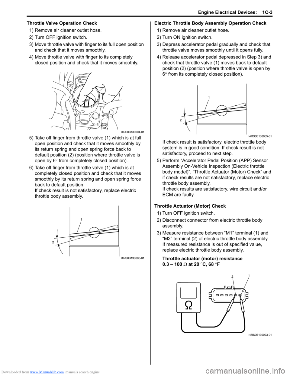
3) Move throttle valve with finger to its full open position and check that it moves smoothly.
4) Move throttle valve with fi nger to its completely
closed position and check that it moves smoothly.
5) Take off finger from throttle valve (1) which is at full open position and check that it moves smoothly by
its return spring and open spring force back to
default position (2) (positio n where throttle valve is
open by 6 ° from completely closed position).
6) Take off finger from throttle valve (1) which is at completely closed position and check that it moves
smoothly by its return spring and open spring force
back to default position.
If check result is not satisfactory, replace electric
throttle body assembly. Electric Throttle Body
Assembly Operation Check
1) Remove air cleaner outlet hose.
2) Turn ON ignition switch.
3) Depress accelerator pedal gradually and check that throttle valve moves smoo thly until it opens fully.
4) Release accelerator pedal depressed in Step 3) and check that throttle valve (1) moves back to default
position (2) (position where throttle valve is open by
6° from its completely closed position).
If check result is satisfactory, electric throttle body
system is in good condition. If check result is not
satisfactory, proceed to next step.
5) Perform “Accelerator Pe dal Position (APP) Sensor
Assembly On-Vehicle Inspection (Electric throttle
body model)”, “Throttle Actuator (Motor) Check” and
if check results are not satisfactory, replace electric
throttle body assembly.
If check results are satisfactory, wire circuit and/or
ECM are faulty.
Throttle Actuator (Motor) Check 1) Turn OFF ignition switch.
2) Disconnect connector from electric throttle body assembly.
3) Measure resistance between “M1” terminal (1) and “M2” terminal (2) of electric throttle body assembly.
If measured resistance is out of specified value,
replace electric throttle body assembly.
Throttle actuator (motor) resistance
0.3 – 100 Ω at 20 °C, 68 °F
I4RS0B130004-01
1
2
I4RS0B130005-01
1
2
I4RS0B130005-01
2 1
I4RS0B130023-01
Page 276 of 1496
Downloaded from www.Manualslib.com manuals search engine 1C-4 Engine Electrical Devices:
TP Sensor Performance Check1) Remove air cleaner outlet hose.
2) Turn OFF ignition switch.
3) Disconnect connector from electric throttle body assembly.
4) Check TP sensor (main and sub) output voltage as following steps.
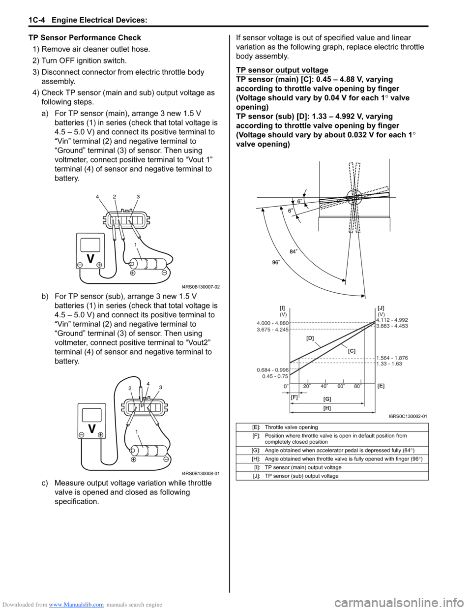
a) For TP sensor (main), arrange 3 new 1.5 V batteries (1) in series (c heck that total voltage is
4.5 – 5.0 V) and connect its positive terminal to
“Vin” terminal (2) and negative terminal to
“Ground” terminal (3) of sensor. Then using
voltmeter, connect positive terminal to “Vout 1”
terminal (4) of sensor and negative terminal to
battery.
b) For TP sensor (sub), arrange 3 new 1.5 V batteries (1) in series (c heck that total voltage is
4.5 – 5.0 V) and connect its positive terminal to
“Vin” terminal (2) and negative terminal to
“Ground” terminal (3) of sensor. Then using
voltmeter, connect positive terminal to “Vout2”
terminal (4) of sensor and negative terminal to
battery.
c) Measure output voltage variation while throttle valve is opened and closed as following
specification. If sensor voltage is out of specified value and linear
variation as the following gra
ph, replace electric throttle
body assembly.
TP sensor output voltage
TP sensor (main) [C]: 0.45 – 4.88 V, varying
according to throttle valve opening by finger
(Voltage should vary by 0.04 V for each 1° valve
opening)
TP sensor (sub) [D]: 1.33 – 4.992 V, varying
according to throttle valve opening by finger
(Voltage should vary by about 0.032 V for each 1 °
valve opening)
1
42 3
I4RS0B130007-02
1
3
2 4
I4RS0B130008-01
[E]: Throttle valve opening
[F]: Position where throttle valve is open in default position from completely closed position
[G]: Angle obtained when accelerator pedal is depressed fully (84 °)
[H]: Angle obtained when throttle valve is fully opened with finger (96 °)
[I]: TP sensor (main) output voltage
[J]: TP sensor (sub) output voltage
[D]
[C][J]
(V)
[I]
(V)
[F] [G] [E]
0.45 - 0.75
0.684 - 0.996 3.675 - 4.245 4.000 - 4.880
1.33 - 1.63 1.564 - 1.876 3.883 - 4.453 4.112 - 4.992
[H]
I6RS0C130002-01
Page 277 of 1496
Downloaded from www.Manualslib.com manuals search engine Engine Electrical Devices: 1C-5
Electric Throttle Body System CalibrationS7RS0B1306004
NOTE
If working the service described under the
“Precautions of Electric Throttle Body
System Calibration in Section 1A” perform
following steps for electric throttle body
system calibration.
1) If electric throttle body assembly and/or APP sensor
assembly are replaced, perform following steps.
a) Disconnect negative cable at battery for 20 seconds or more for the purpose of clearing
calibration data of closed throttle position from
memory in ECM.
b) Connect negative cable to battery.
2) Keep ignition switch at ON position for 5 seconds or more without running engine.
APP Sensor Assembly On-Vehicle InspectionS7RS0B1306005
1) Check that APP sensor a ssembly has been mounted
to vehicle body properly (no pinched floor carpet,
etc.).
If mounting is not pro perly, reinstall APP sensor
assembly properly refe rring to “APP Sensor
Assembly Removal and Installation”.
2) Connect scan tool to DLC with ignition switch turned OFF.
3) Turn ON ignition switch and select “Data List” mode on scan tool.
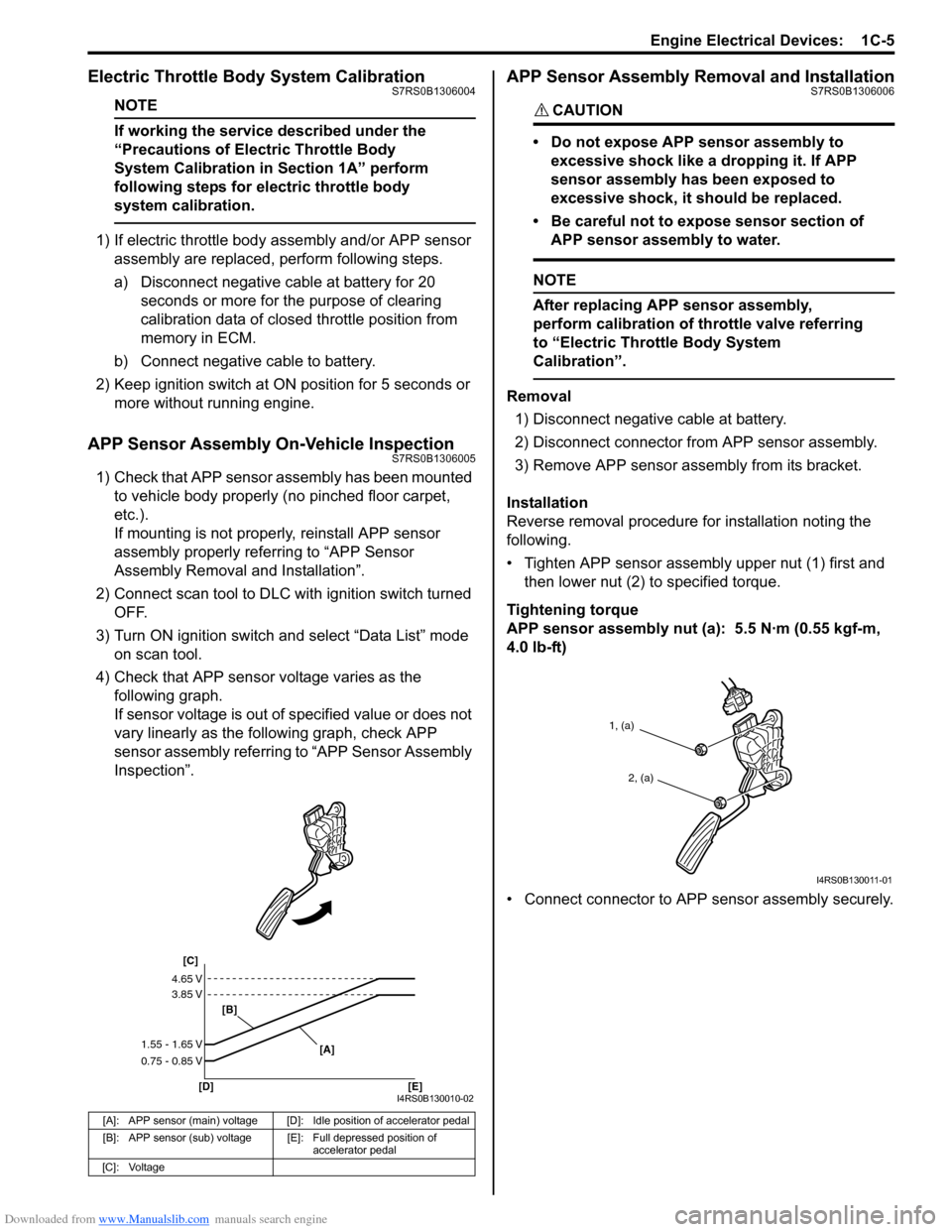
4) Check that APP sensor voltage varies as the following graph.
If sensor voltage is out of specified value or does not
vary linearly as the fo llowing graph, check APP
sensor assembly referring to “APP Sensor Assembly
Inspection”.
APP Sensor Assembly Removal and InstallationS7RS0B1306006
CAUTION!
• Do not expose APP sensor assembly to
excessive shock like a dropping it. If APP
sensor assembly has been exposed to
excessive shock, it should be replaced.
• Be careful not to expose sensor section of APP sensor assembly to water.
NOTE
After replacing APP sensor assembly,
perform calibration of th rottle valve referring
to “Electric Throttle Body System
Calibration”.
Removal
1) Disconnect negative cable at battery.
2) Disconnect connector from APP sensor assembly.
3) Remove APP sensor asse mbly from its bracket.
Installation
Reverse removal procedure for installation noting the
following.
• Tighten APP sensor assembly upper nut (1) first and then lower nut (2) to specified torque.
Tightening torque
APP sensor assembly nut (a): 5.5 N·m (0.55 kgf-m,
4.0 lb-ft)
• Connect connector to APP sensor assembly securely.
[A]: APP sensor (main) voltage [D]: Idle position of accelerator pedal
[B]: APP sensor (sub) voltage [E]: Full depressed position of
accelerator pedal
[C]: Voltage
[C]
[B]
[D] [E] [A]
4.65 V
3.85 V
1.55 - 1.65 V
0.75 - 0.85 V
I4RS0B130010-02
1, (a)
2, (a)
I4RS0B130011-01
Page 278 of 1496
Downloaded from www.Manualslib.com manuals search engine 1C-6 Engine Electrical Devices:
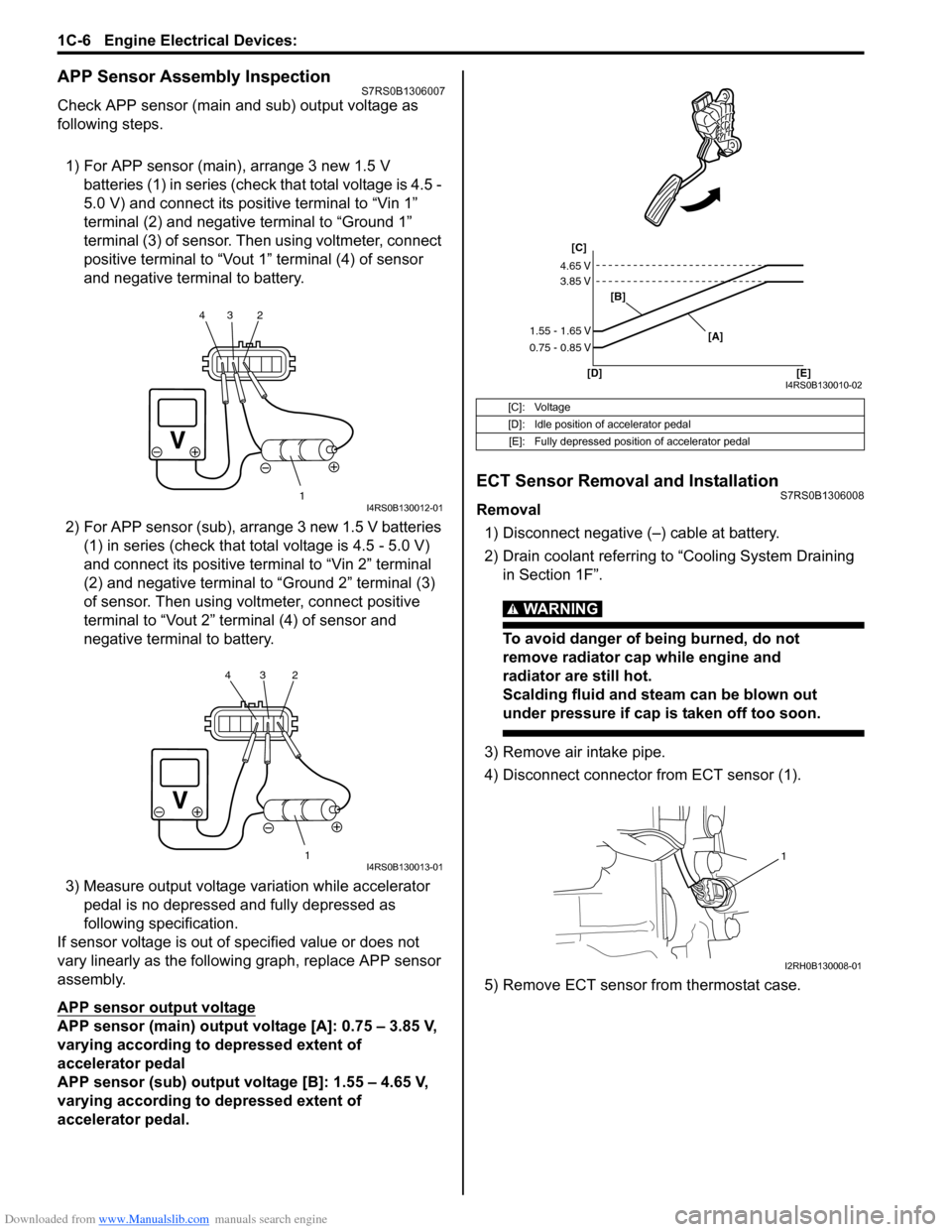
APP Sensor Assembly InspectionS7RS0B1306007
Check APP sensor (main and sub) output voltage as
following steps.
1) For APP sensor (main) , arrange 3 new 1.5 V
batteries (1) in series (check that total voltage is 4.5 -
5.0 V) and connect its positive terminal to “Vin 1”
terminal (2) and negative terminal to “Ground 1”
terminal (3) of sensor. Then using voltmeter, connect
positive terminal to “Vout 1” terminal (4) of sensor
and negative terminal to battery.
2) For APP sensor (s ub), arrange 3 new 1.5 V batteries
(1) in series (check that total voltage is 4.5 - 5.0 V)
and connect its positive terminal to “Vin 2” terminal
(2) and negative terminal to “Ground 2” terminal (3)
of sensor. Then using volt meter, connect positive
terminal to “Vout 2” terminal (4) of sensor and
negative termin al to battery.
3) Measure output voltage variation while accelerator pedal is no depressed and fully depressed as
following specification.
If sensor voltage is out of specified value or does not
vary linearly as the followin g graph, replace APP sensor
assembly.
APP sensor output voltage
APP sensor (main) output voltage [A]: 0.75 – 3.85 V,
varying according to depressed extent of
accelerator pedal
APP sensor (sub) output voltage [B]: 1.55 – 4.65 V,
varying according to depressed extent of
accelerator pedal.
ECT Sensor Removal and InstallationS7RS0B1306008
Removal
1) Disconnect negative (–) cable at battery.
2) Drain coolant referring to “Cooling System Draining in Section 1F”.
WARNING!
To avoid danger of being burned, do not
remove radiator cap while engine and
radiator are still hot.
Scalding fluid and steam can be blown out
under pressure if cap is taken off too soon.
3) Remove air intake pipe.
4) Disconnect connector from ECT sensor (1).
5) Remove ECT sensor from thermostat case.
1
234I4RS0B130012-01
1
234I4RS0B130013-01
[C]: Voltage
[D]: Idle position of accelerator pedal
[E]: Fully depressed position of accelerator pedal
[C]
[B]
[D] [E] [A]
4.65 V
3.85 V
1.55 - 1.65 V
0.75 - 0.85 V
I4RS0B130010-02
1
I2RH0B130008-01
Page 279 of 1496
Downloaded from www.Manualslib.com manuals search engine Engine Electrical Devices: 1C-7
Installation
Reverse removal procedure noting the following.
• Clean mating surfaces of ECT sensor and thermostat case.
• Check O-ring for damage and replace, if necessary.
• Tighten ECT sensor (1) to specified torque.
Tightening torque
ECT sensor (a): 15 N·m (1.5 kgf-m, 11.0 lb-ft)
• Connect connector to ECT sensor securely.
• Refill coolant referring to “Cooling System Flush and
Refill in Section 1F”.
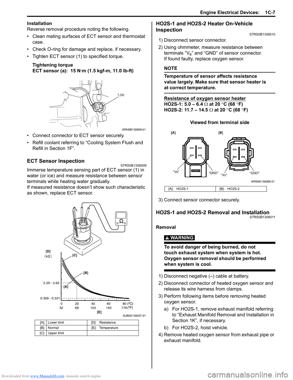
ECT Sensor InspectionS7RS0B1306009
Immerse temperature sensing part of ECT sensor (1) in
water (or ice) and measure resistance between sensor
terminals while heating water gradually.
If measured resistance doesn’t show such characteristic
as shown, replace ECT sensor.
HO2S-1 and HO2S-2 Heater On-Vehicle
Inspection
S7RS0B1306010
1) Disconnect sensor connector.
2) Using ohmmeter, measure resistance between terminals “V
B” and “GND” of sensor connector.
If found faulty, replace oxygen sensor.
NOTE
Temperature of sensor affects resistance
value largely. Make sure that sensor heater is
at correct temperature.
Resistance of oxygen sensor heater
HO2S-1: 5.0 – 6.4 Ω at 20 °C (68 °F)
HO2S-2: 11.7 – 14.5 Ω at 20 °C (68 °F)
Viewed from terminal side
3) Connect sensor co nnector securely.
HO2S-1 and HO2S-2 Removal and InstallationS7RS0B1306011
Removal
WARNING!
To avoid danger of being burned, do not
touch exhaust system when system is hot.
Oxygen sensor removal should be performed
when system is cool.
1) Disconnect negative (–) cable at battery.
2) Disconnect connector of heated oxygen sensor and
release its wire harness from clamps.
3) Perform following items before removing heated oxygen sensor.
a) For HO2S-1, remove exhaust manifold referring to “Exhaust Manifold Remo val and Installation in
Section 1K”, if necessary.
b) For HO2S-2, hoist vehicle.
4) Remove heated oxygen sensor from exhaust pipe or exhaust manifold.
[A]: Lower limit [D]: Resistance
[B]: Normal [E]: Temperature
[C]: Upper limit
1,(a)
I2RH0B130009-01
20
0
68
32 104 140 176 40 60 80
[E]
2.29 - 2.62
0.309 - 0.331
[A]
[B]
[C][D]
I5JB0A130037-01
[A]: HO2S-1 [B]: HO2S-2
I4RS0A130006-01