Inspection SUZUKI SWIFT 2005 2.G Service Workshop Manual
[x] Cancel search | Manufacturer: SUZUKI, Model Year: 2005, Model line: SWIFT, Model: SUZUKI SWIFT 2005 2.GPages: 1496, PDF Size: 34.44 MB
Page 309 of 1496
Downloaded from www.Manualslib.com manuals search engine Engine Mechanical: 1D-24
Oil Control Valve InspectionS7RS0B1406016
Oil Control Valve1) Inspect strainer (1) and mating surface (2) of oil control valve for clog or damage. Clean oil control
valve if clog or foreign matter is present on strainer
or mating surface of oil control valve.
Replace oil control valve if its mating surface is
damaged.
2) Check resistance between terminals of oil control
valve.
Oil control valve resistance
6.7 – 7.7 Ω (at 20 °C (68 °F)) Oil Gallery Pipe
Inspect oil gallery pipes No
.1, No.2 (2) and No.3 (3).
Replace if crack, deformation or clog exists.
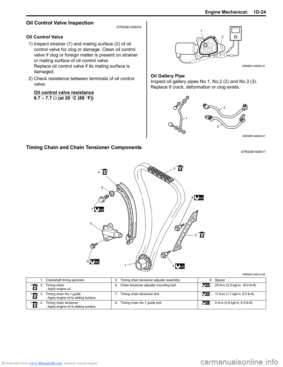
Timing Chain and Chain Tensioner ComponentsS7RS0B1406017
1
2
I3RM0A140028-01
1
3
2
I3RH0B140030-01
I4RS0A140012-04
1. Crankshaft timing sprocket 5. Timing chain tensioner adjuster assembly 9. Spacer
2. Timing chain : Apply engine oil. 6. Chain tensioner adjuster mounting bolt
: 25 N⋅m (2.5 kgf-m, 18.0 lb-ft)
3. Timing chain No.1 guide : Apply engine oil to sliding surface. 7. Timing chain tensioner bolt
: 11 N⋅m (1.1 kgf-m, 8.0 lb-ft)
4. Timing chain tensioner : Apply engine oil to sliding surface. 8. Timing chain No.1 guide bolt
: 9 N⋅m (0.9 kgf-m, 6.5 lb-ft)
Page 312 of 1496
Downloaded from www.Manualslib.com manuals search engine 1D-27 Engine Mechanical:
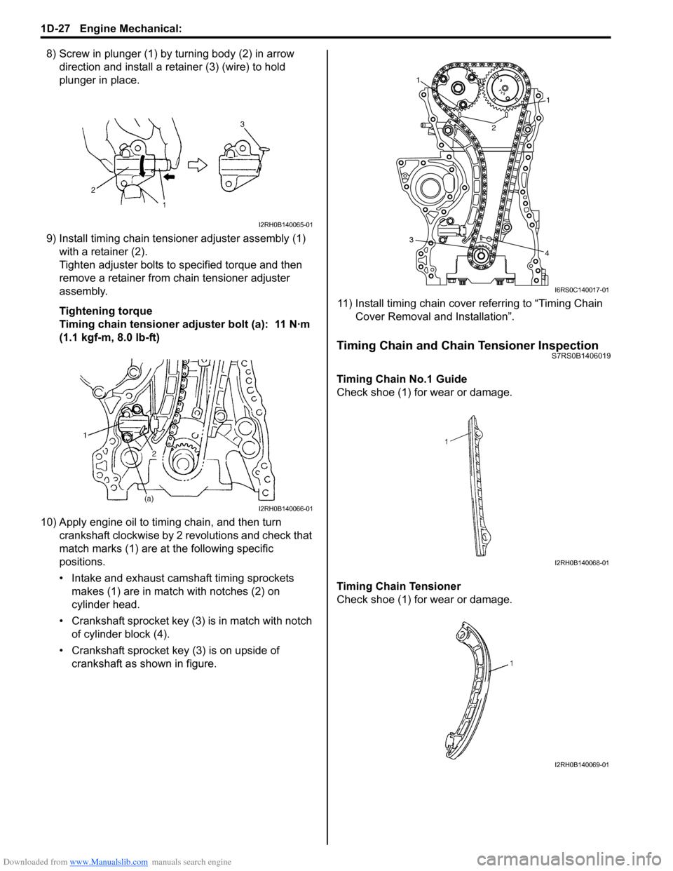
8) Screw in plunger (1) by turning body (2) in arrow direction and install a reta iner (3) (wire) to hold
plunger in place.
9) Install timing chain tensioner adjuster assembly (1) with a retainer (2).
Tighten adjuster bolts to specified torque and then
remove a retainer from chain tensioner adjuster
assembly.
Tightening torque
Timing chain tensioner adjuster bolt (a): 11 N·m
(1.1 kgf-m, 8.0 lb-ft)
10) Apply engine oil to timing chain, and then turn crankshaft clockwise by 2 revolutions and check that
match marks (1) are at the following specific
positions.
• Intake and exhaust camshaft timing sprockets makes (1) are in match with notches (2) on
cylinder head.
• Crankshaft sprocket key (3) is in match with notch of cylinder block (4).
• Crankshaft sprocket key (3) is on upside of crankshaft as shown in figure. 11) Install timing chain cover referring to “Timing Chain
Cover Removal and Installation”.
Timing Chain and Chain Tensioner InspectionS7RS0B1406019
Timing Chain No.1 Guide
Check shoe (1) for wear or damage.
Timing Chain Tensioner
Check shoe (1) for wear or damage.
I2RH0B140065-01
I2RH0B140066-01
1
1
2
3 4
I6RS0C140017-01
I2RH0B140068-01
I2RH0B140069-01
Page 316 of 1496
Downloaded from www.Manualslib.com manuals search engine 1D-31 Engine Mechanical:
7) Install camshaft housing.
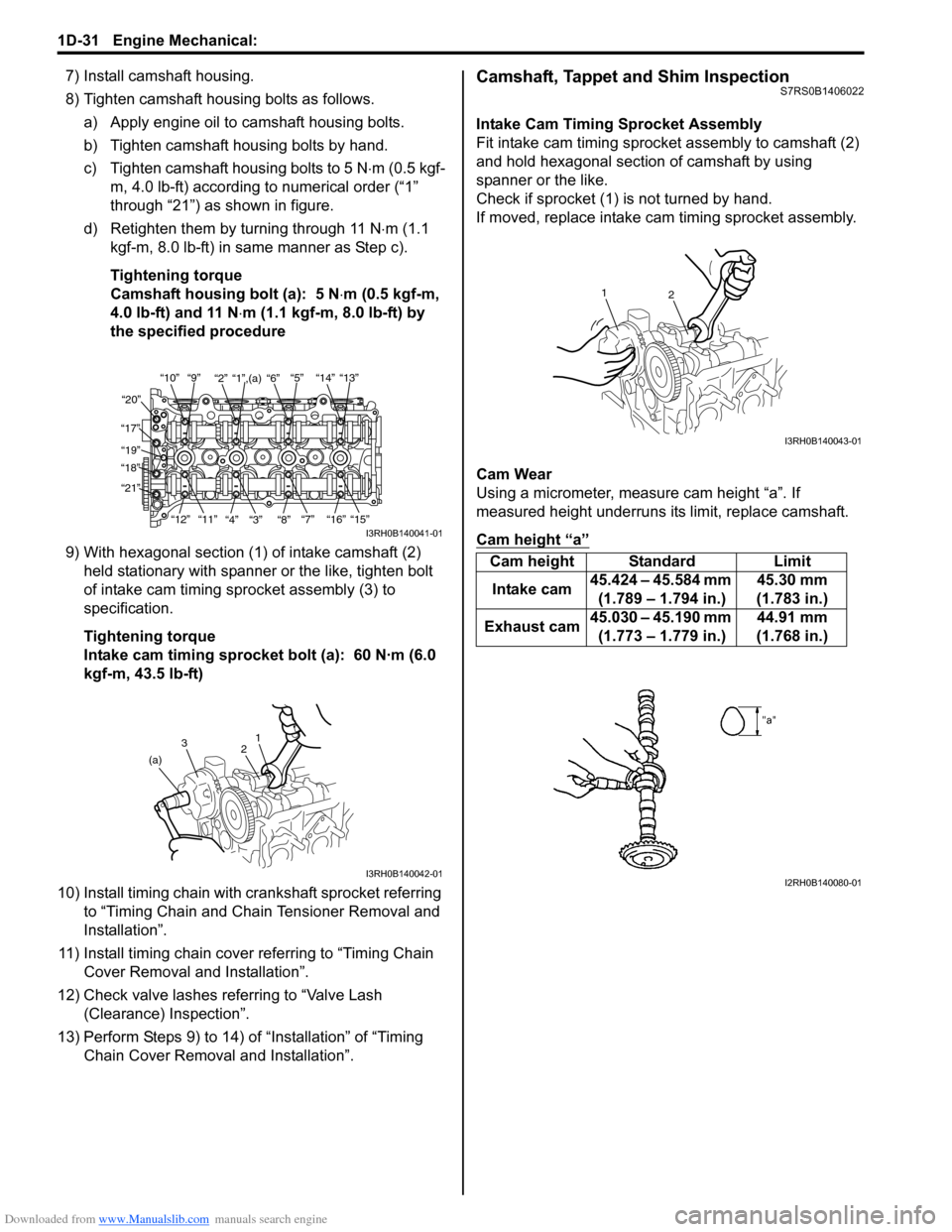
8) Tighten camshaft housing bolts as follows.a) Apply engine oil to camshaft housing bolts.
b) Tighten camshaft housing bolts by hand.
c) Tighten camshaft housing bolts to 5 N ⋅m (0.5 kgf-
m, 4.0 lb-ft) according to numerical order (“1”
through “21”) as shown in figure.
d) Retighten them by turning through 11 N⋅ m (1.1
kgf-m, 8.0 lb-ft) in same manner as Step c).
Tightening torque
Camshaft housing bolt (a): 5 N ⋅m (0.5 kgf-m,
4.0 lb-ft) and 11 N ⋅m (1.1 kgf-m, 8.0 lb-ft) by
the specified procedure
9) With hexagonal section (1) of intake camshaft (2) held stationary with spanner or the like, tighten bolt
of intake cam timing sp rocket assembly (3) to
specification.
Tightening torque
Intake cam timing sprocket bolt (a): 60 N·m (6.0
kgf-m, 43.5 lb-ft)
10) Install timing chain with cr ankshaft sprocket referring
to “Timing Chain and Chain Tensioner Removal and
Installation”.
11) Install timing chain cover referring to “Timing Chain Cover Removal and Installation”.
12) Check valve lashes referring to “Valve Lash (Clearance) Inspection”.
13) Perform Steps 9) to 14) of “Installation” of “Timing Chain Cover Removal and Installation”.Camshaft, Tappet and Shim InspectionS7RS0B1406022
Intake Cam Timing Sprocket Assembly
Fit intake cam timing sprocket assembly to camshaft (2)
and hold hexagonal section of camshaft by using
spanner or the like.
Check if sprocket (1) is not turned by hand.
If moved, replace intake ca m timing sprocket assembly.
Cam Wear
Using a micrometer, measure cam height “a”. If
measured height underruns its limit, replace camshaft.
Cam height “a”
“10”“9” “2” “1”,(a) “6” “5” “14” “13”
“20”
“17” “19”
“18”
“21”
“12”“11”
“4” “3” “8” “7” “16” “15”
I3RH0B140041-01
1
2
3
(a)
I3RH0B140042-01
Cam height Standard Limit
Intake cam 45.424 – 45.584 mm
(1.789 – 1.794 in.) 45.30 mm
(1.783 in.)
Exhaust cam 45.030 – 45.190 mm
(1.773 – 1.779 in.) 44.91 mm
(1.768 in.)
2
1
I3RH0B140043-01
I2RH0B140080-01
Page 325 of 1496
Downloaded from www.Manualslib.com manuals search engine Engine Mechanical: 1D-40
Valves and Valve Guides InspectionS7RS0B1406026
Valve Guide
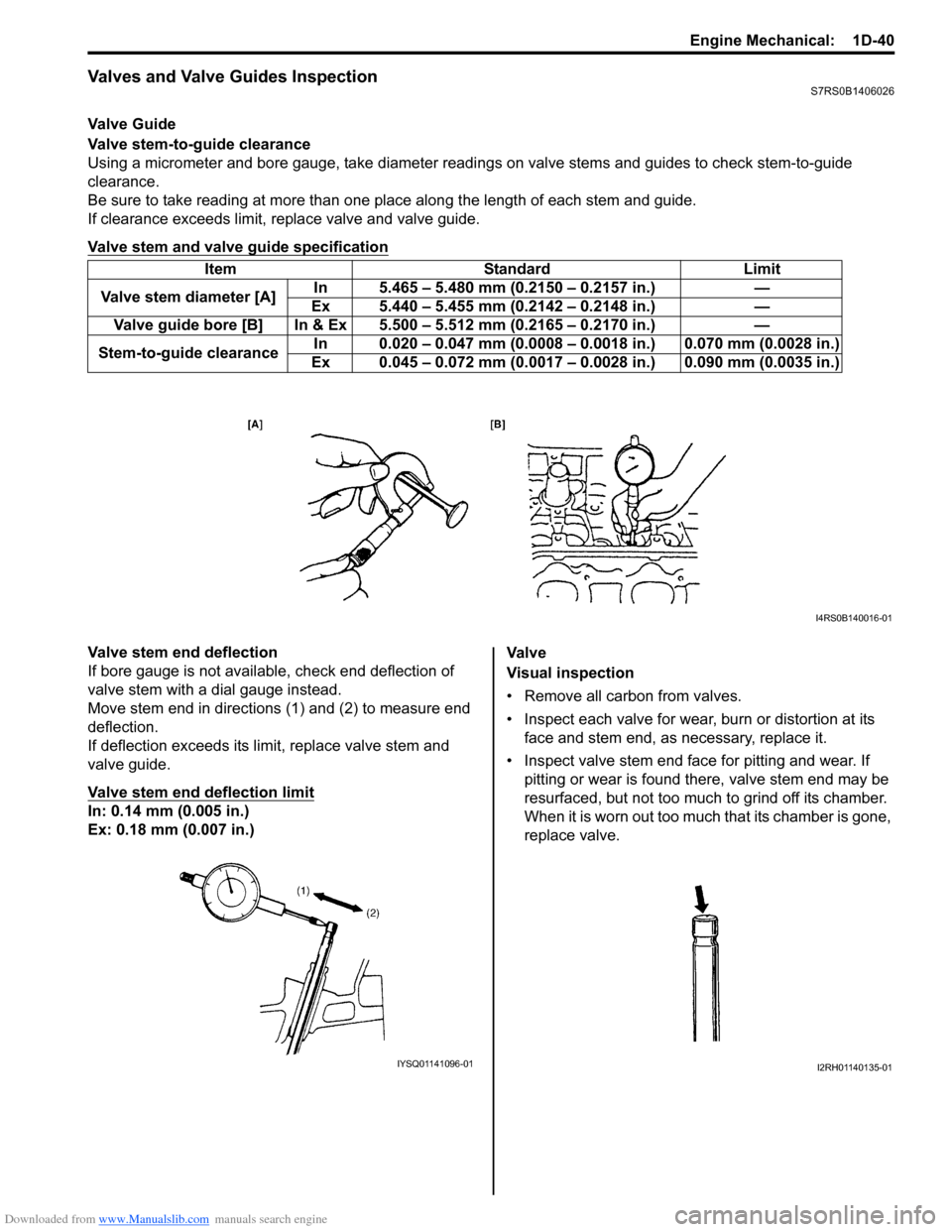
Valve stem-to-guide clearance
Using a micrometer and bore gauge, take diameter readings on valve stems and guides to check stem-to-guide
clearance.
Be sure to take reading at more than one place along the length of each stem and guide.
If clearance exceeds limit, replace valve and valve guide.
Valve stem and valve guide specification
Valve stem end deflection
If bore gauge is not available, check end deflection of
valve stem with a dial gauge instead.
Move stem end in directions (1) and (2) to measure end
deflection.
If deflection exceeds its limit, replace valve stem and
valve guide.
Valve stem end deflection limit
In: 0.14 mm (0.005 in.)
Ex: 0.18 mm (0.007 in.) Va l v e
Visual inspection
• Remove all carbon from valves.
• Inspect each valve for wear, burn or distortion at its
face and stem end, as necessary, replace it.
• Inspect valve stem end face for pitting and wear. If pitting or wear is found there, valve stem end may be
resurfaced, but not too much to grind off its chamber.
When it is worn out too much that its chamber is gone,
replace valve.
Item Standard Limit
Valve stem diameter [A] In 5.465 – 5.480 mm (0.2150 – 0.2157 in.) —
Ex 5.440 – 5.455 mm (0.2142 – 0.2148 in.) —
Valve guide bore [B] In & Ex 5.500 – 5.512 mm (0.2165 – 0.2170 in.) —
Stem-to-guide clearance In 0.020 – 0.047 mm (0.0008 – 0.
0018 in.) 0.070 mm (0.0028 in.)
Ex 0.045 – 0.072 mm (0.0017 – 0. 0028 in.) 0.090 mm (0.0035 in.)
I4RS0B140016-01
IYSQ01141096-01I2RH01140135-01
Page 327 of 1496
Downloaded from www.Manualslib.com manuals search engine Engine Mechanical: 1D-42
Cylinder Head InspectionS7RS0B1406027
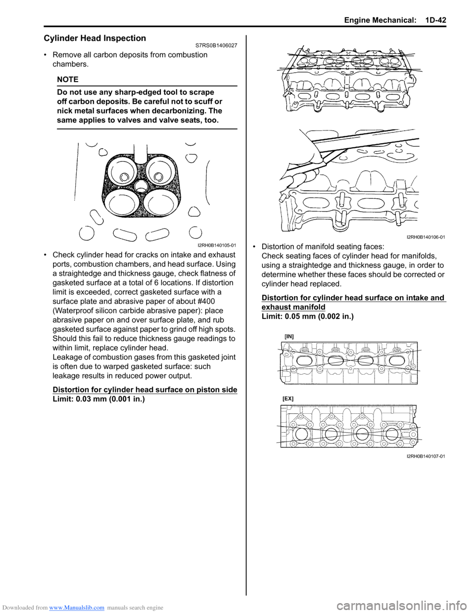
• Remove all carbon deposits from combustion chambers.
NOTE
Do not use any sharp-edged tool to scrape
off carbon deposits. Be careful not to scuff or
nick metal surfaces when decarbonizing. The
same applies to valves and valve seats, too.
• Check cylinder head for cracks on intake and exhaust ports, combustion chambers, and head surface. Using
a straightedge and thickness gauge, check flatness of
gasketed surface at a total of 6 locations. If distortion
limit is exceeded, correct gasketed surface with a
surface plate and abrasive paper of about #400
(Waterproof silicon carbide abrasive paper): place
abrasive paper on and over surface plate, and rub
gasketed surface against paper to grind off high spots.
Should this fail to reduce thickness gauge readings to
within limit, replace cylinder head.
Leakage of combustion gases from this gasketed joint
is often due to warped gasketed surface: such
leakage results in reduced power output.
Distortion for cylinder head surface on piston side
Limit: 0.03 mm (0.001 in.) • Distortion of manifold seating faces:
Check seating faces of cylinder head for manifolds,
using a straightedge and thickness gauge, in order to
determine whether these faces should be corrected or
cylinder head replaced.
Distortion for cylinder head surface on intake and
exhaust manifold
Limit: 0.05 mm (0.002 in.)
I2RH0B140105-01
I2RH0B140106-01
I2RH0B140107-01
Page 328 of 1496
Downloaded from www.Manualslib.com manuals search engine 1D-43 Engine Mechanical:
Valve Spring InspectionS7RS0B1406028
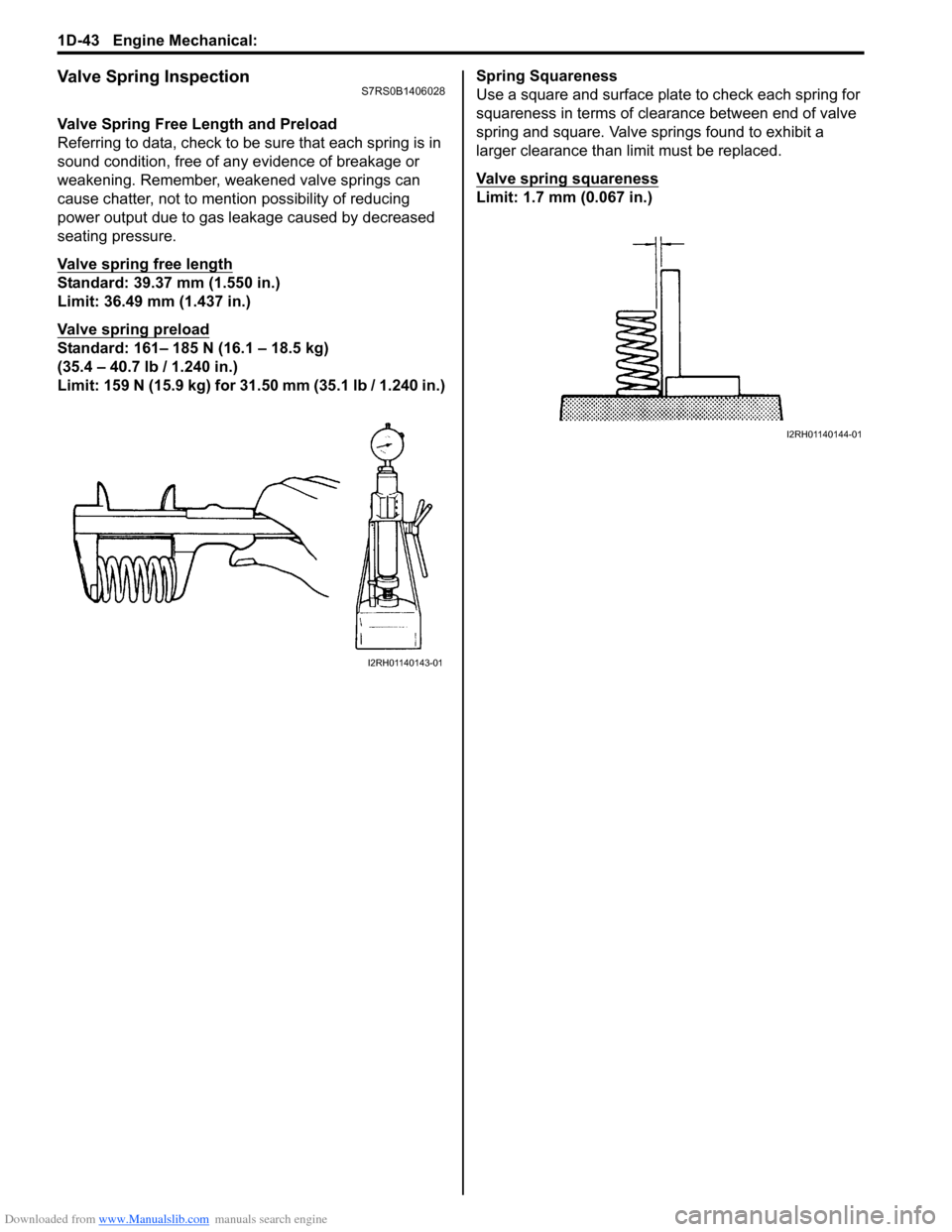
Valve Spring Free Length and Preload
Referring to data, check to be sure that each spring is in
sound condition, free of any evidence of breakage or
weakening. Remember, weakened valve springs can
cause chatter, not to mention possibility of reducing
power output due to gas leakage caused by decreased
seating pressure.
Valve spring free length
Standard: 39.37 mm (1.550 in.)
Limit: 36.49 mm (1.437 in.)
Valve spring preload
Standard: 161– 185 N (16.1 – 18.5 kg)
(35.4 – 40.7 lb / 1.240 in.)
Limit: 159 N (15.9 kg) for 31.50 mm (35.1 lb / 1.240 in.) Spring Squareness
Use a square and surface plate to check each spring for
squareness in terms of clearance between end of valve
spring and square. Valve springs found to exhibit a
larger clearance than limit must be replaced.
Valve spring squareness
Limit: 1.7 mm (0.067 in.)
I2RH01140143-01
I2RH01140144-01
Page 329 of 1496
Downloaded from www.Manualslib.com manuals search engine Engine Mechanical: 1D-44
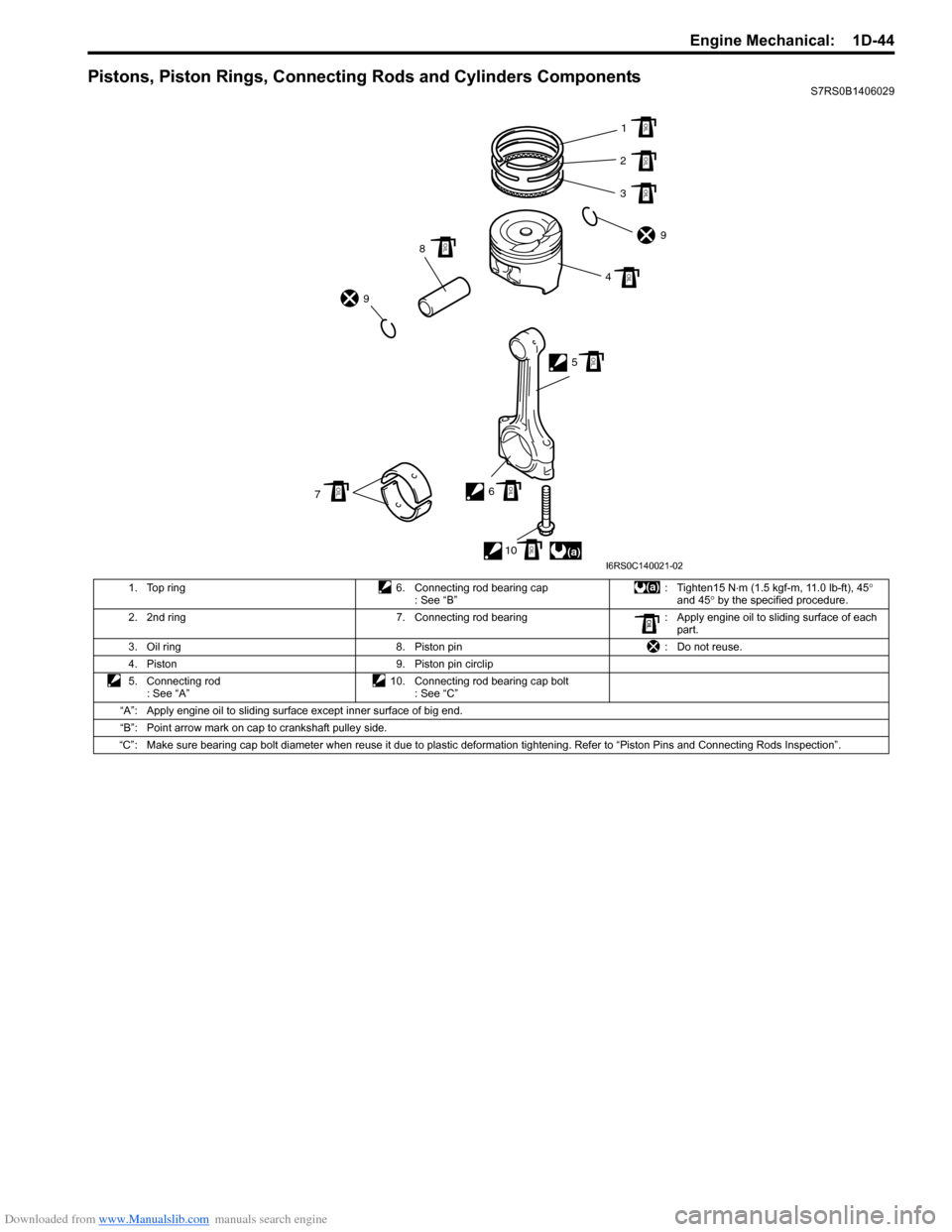
Pistons, Piston Rings, Connecting Rods and Cylinders ComponentsS7RS0B1406029
1. Top ring 6. Connecting rod bearing cap : See “B”: Tighten15 N
⋅m (1.5 kgf-m, 11.0 lb-ft), 45 °
and 45 ° by the specified procedure.
2. 2nd ring 7. Connecting rod bearing : Apply engine oil to sliding surface of each
part.
3. Oil ring 8. Piston pin : Do not reuse.
4. Piston 9. Piston pin circlip
5. Connecting rod : See “A” 10. Connecting rod bearing cap bolt
: See “C”
“A”: Apply engine oil to sliding surface except inner surface of big end.
“B”: Point arrow mark on cap to crankshaft pulley side.
“C”: Make sure bearing cap bolt diameter when reuse it due to plastic deformation tightening. Refer to “Piston Pins and Connecti ng Rods Inspection”.
(a)1
2
3
9
4
5
6 10
7 8
9
OIL
OIL
OIL
OIL
OIL
OIL
OIL
OIL
OIL
I6RS0C140021-02
Page 330 of 1496
Downloaded from www.Manualslib.com manuals search engine 1D-45 Engine Mechanical:
Pistons, Piston Rings, Connecting Rods and
Cylinders Removal and Installation
S7RS0B1406030
Removal1) Remove engine assembly from vehicle referring to “Engine Assembly Removal and Installation”.
2) Remove cylinder head referring to “Valves and Cylinder Head Removal and Installation”.
3) Mark cylinder number on all pistons, connecting rods
and connecting rod caps using silver pencil or quick
drying paint.
4) Remove rod bearing caps.
5) Decarbonize top of cylinder bore before removing piston from cylinder.
6) Push piston and connecting rod assembly out through the top of cylinder bore.
Installation 1) Apply engine oil to pistons, rings, cylinder walls, connecting rod bearings and crank pins.
NOTE
Do not apply oil between connecting rod and
bearing or between bearing cap and bearing.
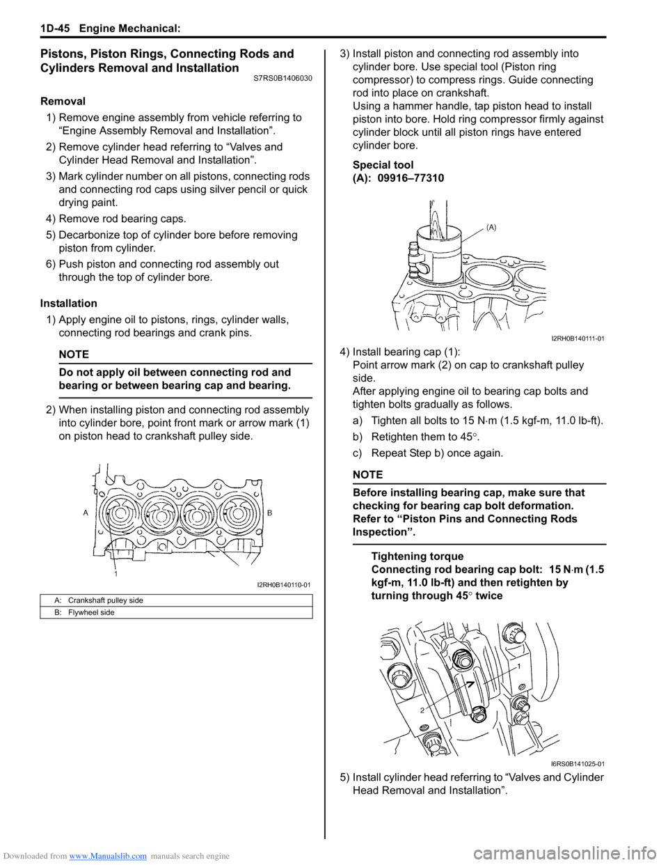
2) When installing piston and connecting rod assembly into cylinder bore, point front mark or arrow mark (1)
on piston head to crankshaft pulley side. 3) Install piston and connecting rod assembly into
cylinder bore. Use special tool (Piston ring
compressor) to compress rings. Guide connecting
rod into place on crankshaft.
Using a hammer handle, tap piston head to install
piston into bore. Hold ring compressor firmly against
cylinder block until all piston rings have entered
cylinder bore.
Special tool
(A): 09916–77310
4) Install bearing cap (1): Point arrow mark (2) on cap to crankshaft pulley
side.
After applying engine oil to bearing cap bolts and
tighten bolts gradually as follows.
a) Tighten all bolts to 15 N ⋅m (1.5 kgf-m, 11.0 lb-ft).
b) Retighten them to 45 °.
c) Repeat Step b) once again.
NOTE
Before installing bearing cap, make sure that
checking for bearing cap bolt deformation.
Refer to “Piston Pins and Connecting Rods
Inspection”.
Tightening torque
Connecting rod bearing cap bolt: 15 N ⋅m (1.5
kgf-m, 11.0 lb-ft) and then retighten by
turning through 45 ° twice
5) Install cylinder head referring to “Valves and Cylinder Head Removal and Installation”.
A: Crankshaft pulley side
B: Flywheel side
I2RH0B140110-01
I2RH0B140111-01
I6RS0B141025-01
Page 332 of 1496
Downloaded from www.Manualslib.com manuals search engine 1D-47 Engine Mechanical:
Cylinders, Pistons and Piston Rings InspectionS7RS0B1406032
Cylinder
Visual inspection
Inspect cylinder walls for scratches, roughness or ridges
which indicate excessive wear. If cylinder bore is very
rough or deeply scratched, or ridged, rebore cylinder and
use over size piston.
Cylinder bore diameter, taper and out-of-round
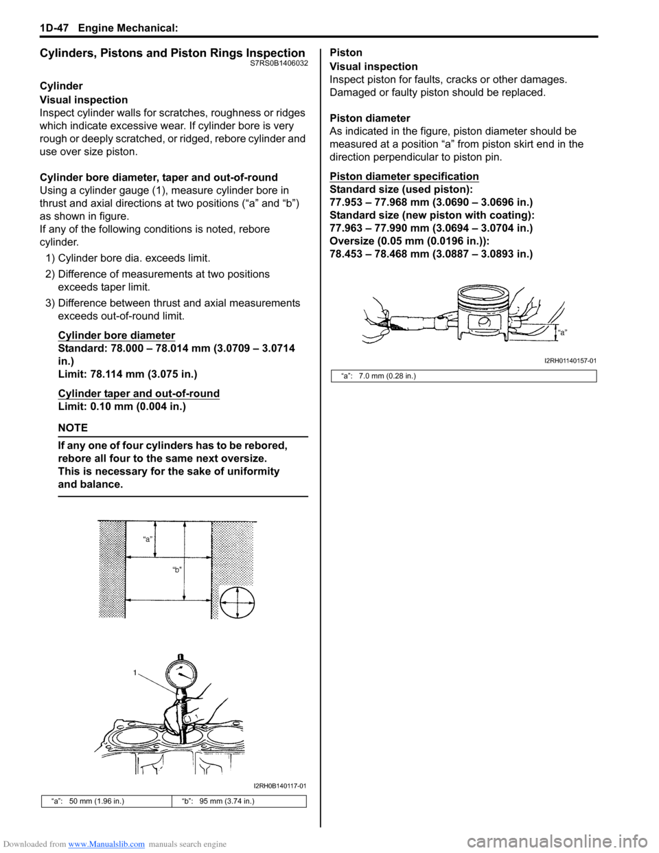
Using a cylinder gauge (1), measure cylinder bore in
thrust and axial directions at two positions (“a” and “b”)
as shown in figure.
If any of the following conditions is noted, rebore
cylinder.1) Cylinder bore dia. exceeds limit.
2) Difference of measurements at two positions exceeds taper limit.
3) Difference between thrust and axial measurements exceeds out-of-round limit.
Cylinder bore diameter
Standard: 78.000 – 78.014 mm (3.0709 – 3.0714
in.)
Limit: 78.114 mm (3.075 in.)
Cylinder taper and out-of-round
Limit: 0.10 mm (0.004 in.)
NOTE
If any one of four cylinders has to be rebored,
rebore all four to the same next oversize.
This is necessary for the sake of uniformity
and balance.
Piston
Visual inspection
Inspect piston for faults, cracks or other damages.
Damaged or faulty piston should be replaced.
Piston diameter
As indicated in the figure, piston diameter should be
measured at a position “a” from piston skirt end in the
direction perpendicular to piston pin.
Piston diameter specification
Standard size (used piston):
77.953 – 77.968 mm (3.0690 – 3.0696 in.)
Standard size (new piston with coating):
77.963 – 77.990 mm (3.0694 – 3.0704 in.)
Oversize (0.05 mm (0.0196 in.)):
78.453 – 78.468 mm (3.0887 – 3.0893 in.)
“a”: 50 mm (1.96 in.) “b”: 95 mm (3.74 in.)
I2RH0B140117-01
“a”: 7.0 mm (0.28 in.)
I2RH01140157-01
Page 334 of 1496
Downloaded from www.Manualslib.com manuals search engine 1D-49 Engine Mechanical:
Piston Pins and Connecting Rods InspectionS7RS0B1406033
Piston Pin
Visual inspection
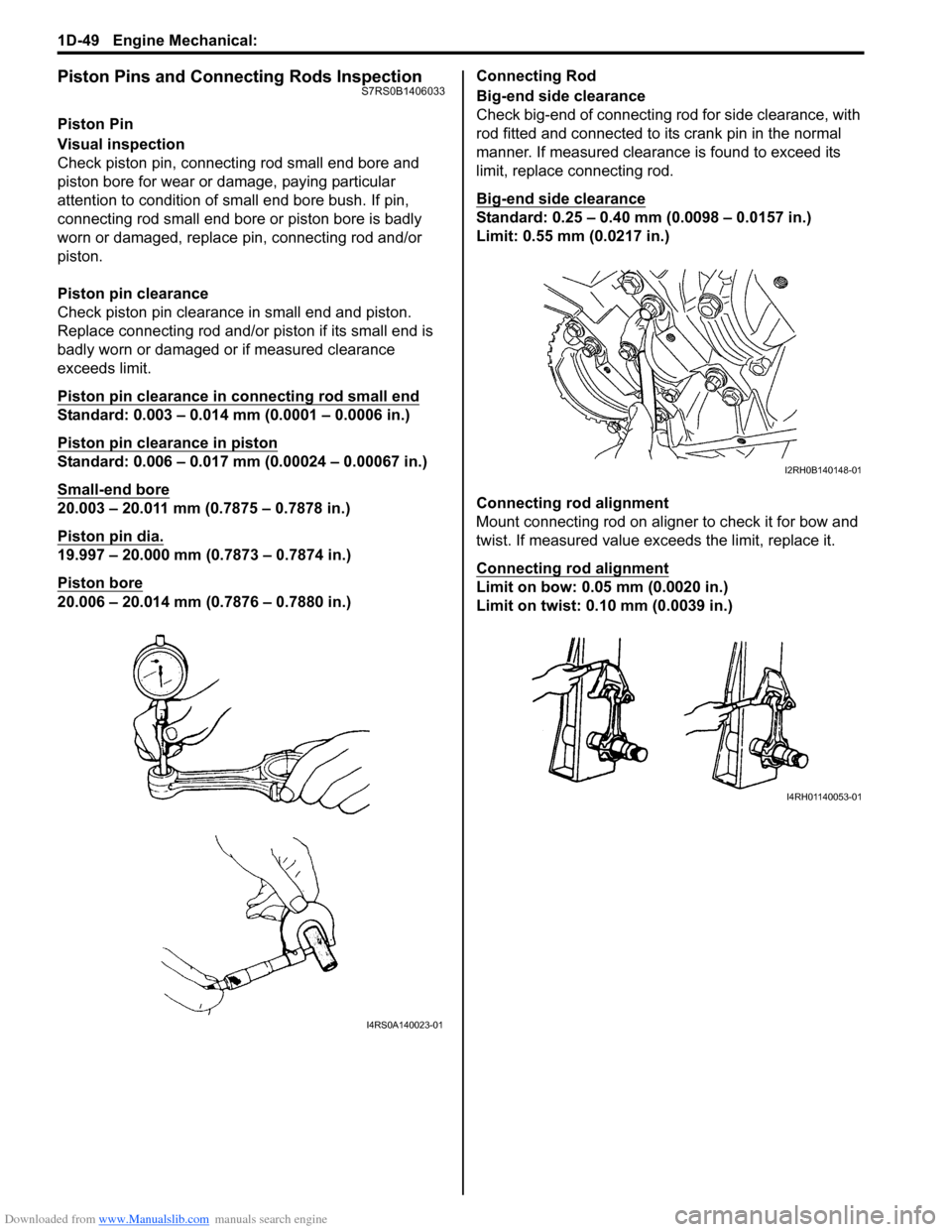
Check piston pin, connecting rod small end bore and
piston bore for wear or damage, paying particular
attention to condition of small end bore bush. If pin,
connecting rod small end bore or piston bore is badly
worn or damaged, replace pin, connecting rod and/or
piston.
Piston pin clearance
Check piston pin clearance in small end and piston.
Replace connecting rod and/or piston if its small end is
badly worn or damaged or if measured clearance
exceeds limit.
Piston pin clearance in connecting rod small end
Standard: 0.003 – 0.014 mm (0.0001 – 0.0006 in.)
Piston pin clearance in piston
Standard: 0.006 – 0.017 mm (0.00024 – 0.00067 in.)
Small-end bore
20.003 – 20.011 mm (0.7875 – 0.7878 in.)
Piston pin dia.
19.997 – 20.000 mm (0.7873 – 0.7874 in.)
Piston bore
20.006 – 20.014 mm (0.7876 – 0.7880 in.)Connecting Rod
Big-end side clearance
Check big-end of connecting rod for side clearance, with
rod fitted and connected to its crank pin in the normal
manner. If measured clearance is found to exceed its
limit, replace connecting rod.
Big-end side clearance
Standard: 0.25 – 0.40 mm (0.0098 – 0.0157 in.)
Limit: 0.55 mm (0.0217 in.)
Connecting rod alignment
Mount connecting rod on aligner to check it for bow and
twist. If measured value exceeds the limit, replace it.
Connecting rod alignment
Limit on bow: 0.05 mm (0.0020 in.)
Limit on twist: 0.10 mm (0.0039 in.)
I4RS0A140023-01
I2RH0B140148-01
I4RH01140053-01