1J” SUZUKI SWIFT 2005 2.G Service User Guide
[x] Cancel search | Manufacturer: SUZUKI, Model Year: 2005, Model line: SWIFT, Model: SUZUKI SWIFT 2005 2.GPages: 1496, PDF Size: 34.44 MB
Page 371 of 1496
Downloaded from www.Manualslib.com manuals search engine Engine Cooling System: 1F-8
Thermostat Removal and InstallationS7RS0B1606007
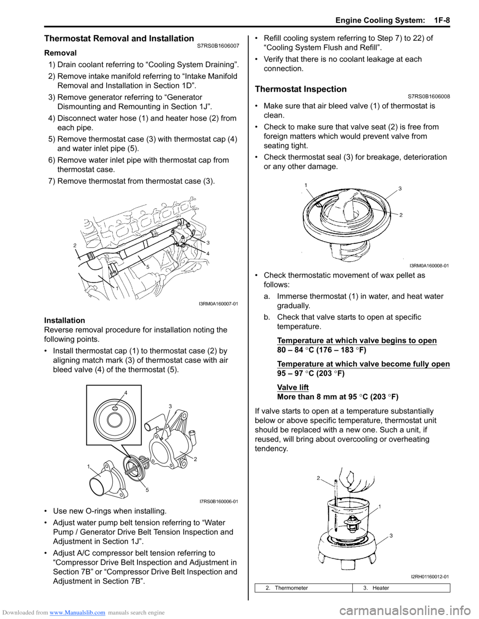
Removal1) Drain coolant referring to “Cooling System Draining”.
2) Remove intake manifold referring to “Intake Manifold Removal and Installa tion in Section 1D”.
3) Remove generator referring to “Generator Dismounting and Remounting in Section 1J”.
4) Disconnect water hose (1) and heater hose (2) from each pipe.
5) Remove thermostat case (3) with thermostat cap (4)
and water inlet pipe (5).
6) Remove water inlet pipe with thermostat cap from thermostat case.
7) Remove thermostat from thermostat case (3).
Installation
Reverse removal procedure for installation noting the
following points.
• Install thermostat cap (1) to thermostat case (2) by aligning match mark (3) of thermostat case with air
bleed valve (4) of the thermostat (5).
• Use new O-rings when installing.
• Adjust water pump belt tension referring to “Water Pump / Generator Drive Belt Tension Inspection and
Adjustment in Section 1J”.
• Adjust A/C compressor belt tension referring to “Compressor Drive Belt Inspection and Adjustment in
Section 7B” or “Compressor Drive Belt Inspection and
Adjustment in Section 7B”. • Refill cooling system referrin
g to Step 7) to 22) of
“Cooling System Flush and Refill”.
• Verify that there is no coolant leakage at each connection.
Thermostat InspectionS7RS0B1606008
• Make sure that air bleed valve (1) of thermostat is clean.
• Check to make sure that va lve seat (2) is free from
foreign matters which would prevent valve from
seating tight.
• Check thermostat seal (3) for breakage, deterioration or any other damage.
• Check thermostatic movement of wax pellet as follows:
a. Immerse thermostat (1) in water, and heat water gradually.
b. Check that valve starts to open at specific temperature.
Temperature at which valve begins to open
80 – 84 °C (176 – 183 °F)
Temperature at which valve become fully open
95 – 97 °C (203 °F)
Va l v e l i ft
More than 8 mm at 95 °C (203 ° F)
If valve starts to open at a temperature substantially
below or above specific temperature, thermostat unit
should be replaced with a new one. Such a unit, if
reused, will bring about ov ercooling or overheating
tendency.
I3RM0A160007-01
4
5 3
1 2
I7RS0B160006-01
2. Thermometer
3. Heater
I3RM0A160008-01
I2RH01160012-01
Page 374 of 1496
Downloaded from www.Manualslib.com manuals search engine 1F-11 Engine Cooling System:
Water Pump Removal and InstallationS7RS0B1606014
Removal1) Disconnect negative cable at battery.
2) Drain coolant.
3) Remove water pump / generator drive belt referring to “Water Pump / Generator Drive Belt Removal and
Installation in Section 1J”.
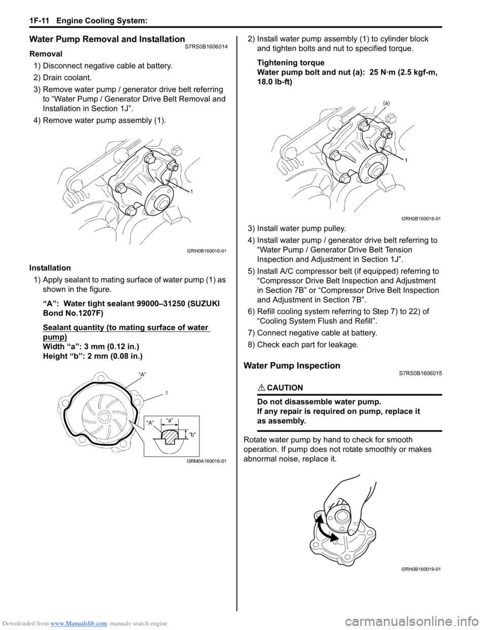
4) Remove water pump assembly (1).
Installation 1) Apply sealant to mating surface of water pump (1) as shown in the figure.
“A”: Water tight sealant 99000–31250 (SUZUKI
Bond No.1207F)
Sealant quantity (to mating surface of water
pump)
Width “a”: 3 mm (0.12 in.)
Height “b”: 2 mm (0.08 in.) 2) Install water pump assemb
ly (1) to cylinder block
and tighten bolts and nut to specified torque.
Tightening torque
Water pump bolt and nut (a): 25 N·m (2.5 kgf-m,
18.0 lb-ft)
3) Install water pump pulley.
4) Install water pump / generator drive belt referring to “Water Pump / Generator Drive Belt Tension
Inspection and Adjustment in Section 1J”.
5) Install A/C compressor belt (if equipped) referring to “Compressor Drive Belt Inspection and Adjustment
in Section 7B” or “Compressor Drive Belt Inspection
and Adjustment in Section 7B”.
6) Refill cooling system referri ng to Step 7) to 22) of
“Cooling System Flush and Refill”.
7) Connect negative cable at battery.
8) Check each part for leakage.
Water Pump InspectionS7RS0B1606015
CAUTION!
Do not disassemble water pump.
If any repair is requir ed on pump, replace it
as assembly.
Rotate water pump by hand to check for smooth
operation. If pump does not rotate smoothly or makes
abnormal noise, replace it.
I2RH0B160016-01
I3RM0A160016-01
I2RH0B160018-01
I2RH0B160019-01
Page 560 of 1496
Downloaded from www.Manualslib.com manuals search engine 4E-21 ABS:
DTC C1057: Power Source CircuitS7RS0B4504014
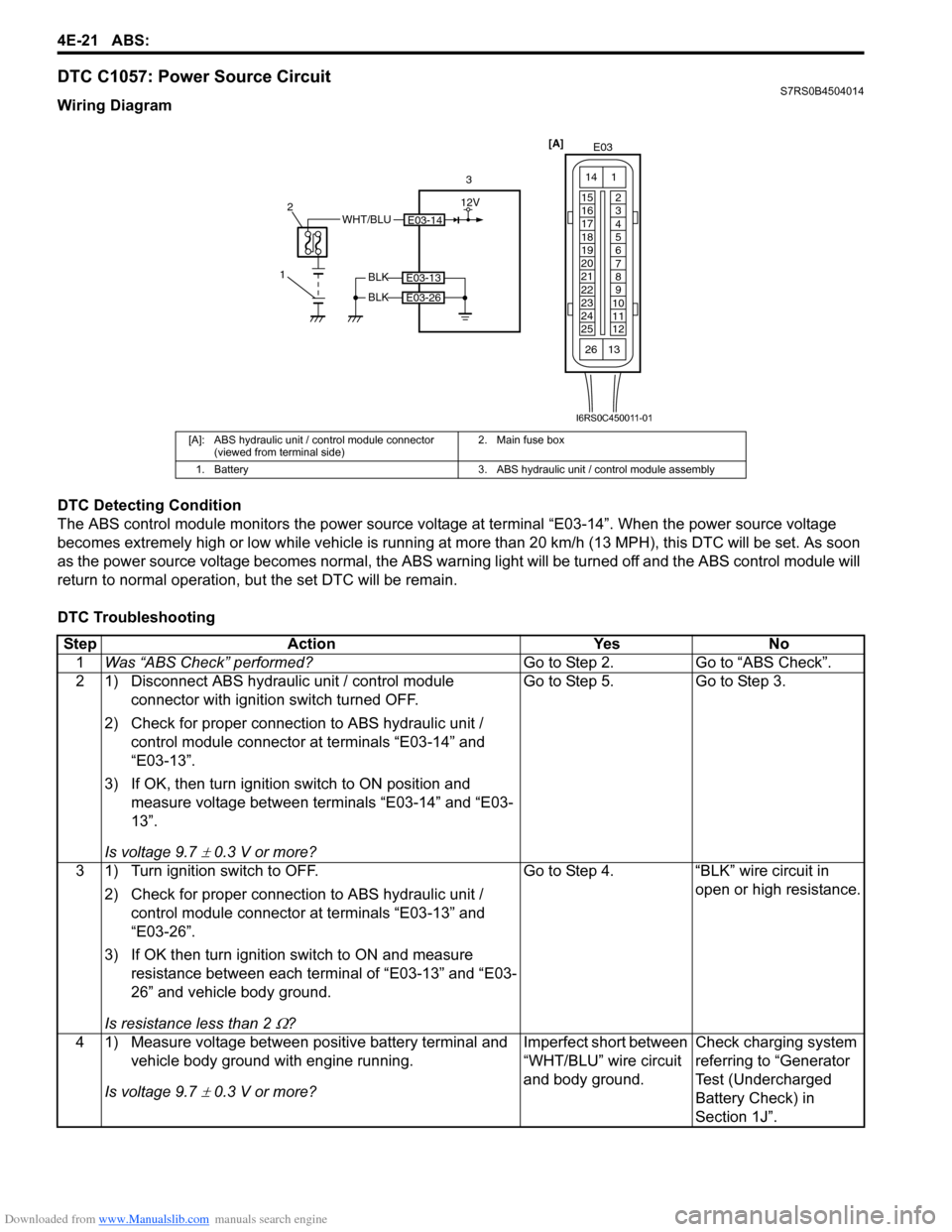
Wiring Diagram
DTC Detecting Condition
The ABS control module monitors the power source voltage at terminal “E03-14”. When the power source voltage
becomes extremely high or low while vehicle is running at more than 20 km/h (13 MPH), this DTC will be set. As soon
as the power source volta ge becomes normal, the ABS warning light will be turned off and the ABS control module will
return to normal operation, bu t the set DTC will be remain.
DTC Troubleshooting
[A]: ABS hydraulic unit / control module connector (viewed from terminal side) 2. Main fuse box
1. Battery 3. ABS hydraulic unit / control module assembly
E03-14WHT/BLU
1 2
3
BLK
BLK
E03-13
E03-26
[A]
E03
15
16
17
18
19
20
21
22
23
24
25 2
3
4
5
6
7
8
9
10
11
12
1
13
14
26
12V
I6RS0C450011-01
Step
Action YesNo
1 Was “ABS Check” performed? Go to Step 2.Go to “ABS Check”.
2 1) Disconnect ABS hydraulic unit / control module connector with ignition switch turned OFF.
2) Check for proper connection to ABS hydraulic unit / control module connector at terminals “E03-14” and
“E03-13”.
3) If OK, then turn ignition switch to ON position and measure voltage between terminals “E03-14” and “E03-
13”.
Is voltage 9.7
± 0.3 V or more? Go to Step 5. Go to Step 3.
3 1) Turn ignition switch to OFF. 2) Check for proper connection to ABS hydraulic unit / control module connector at terminals “E03-13” and
“E03-26”.
3) If OK then turn ignition switch to ON and measure resistance between each terminal of “E03-13” and “E03-
26” and vehicle body ground.
Is resistance less than 2
Ω? Go to Step 4. “BLK” wire circuit in
open or high resistance.
4 1) Measure voltage between positive battery terminal and vehicle body ground with engine running.
Is voltage 9.7
± 0.3 V or more? Imperfect short between
“WHT/BLU” wire circuit
and body ground.
Check charging system
referring to “Generator
Test (Undercharged
Battery Check) in
Section 1J”.
Page 561 of 1496
Downloaded from www.Manualslib.com manuals search engine ABS: 4E-22
DTC C1061: ABS Pump Motor and/or Motor Driver CircuitS7RS0B4504015
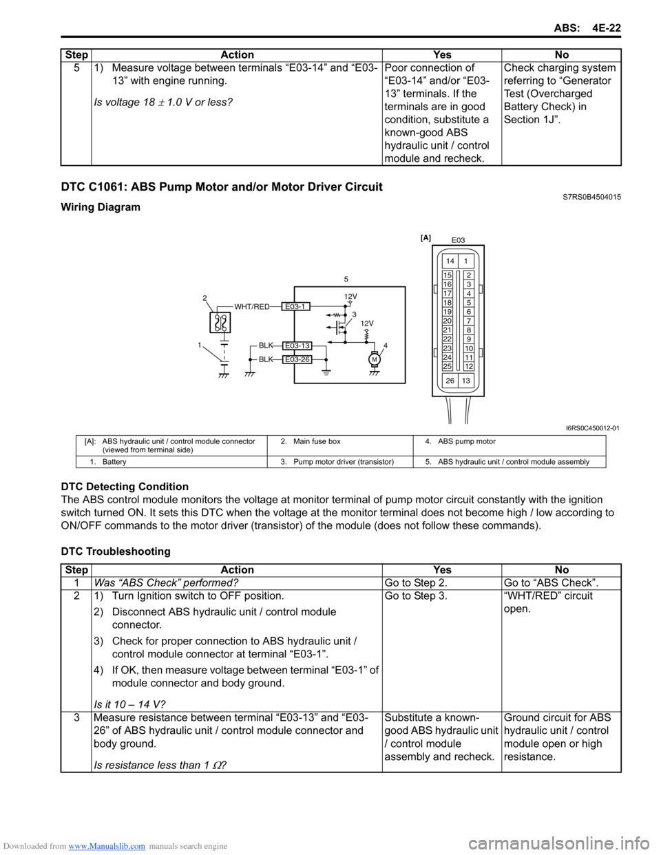
Wiring Diagram
DTC Detecting Condition
The ABS control module monitors the voltage at monitor terminal of pump motor circuit constantly with the ignition
switch turned ON. It sets this DTC when the voltage at the monitor terminal does not become high / low according to
ON/OFF commands to the motor driver (transistor) of the module (does not follow these commands).
DTC Troubleshooting 5 1) Measure voltage between terminals “E03-14” and “E03-
13” with engine running.
Is voltage 18
± 1.0 V or less? Poor connection of
“E03-14” and/or “E03-
13” terminals. If the
terminals are in good
condition, substitute a
known-good ABS
hydraulic unit / control
module and recheck.Check charging system
referring to “Generator
Test (Overcharged
Battery Check) in
Section 1J”.
Step Action Yes No
WHT/RED
1 2
5
BLK
BLK
E03-13
E03-26
[A]
E03
15
16
17
18
19
20
21
22
23
24
25 2
3
4
5
6
7
8
9
10
11
12
1
13
14
26
M
3
4E03-1
12V
12V
I6RS0C450012-01
[A]: ABS hydraulic unit / control module connector (viewed from terminal side) 2. Main fuse box 4. ABS pump motor
1. Battery 3. Pump motor driver (transistor) 5. ABS hydraulic unit / control module assembly
StepAction YesNo
1 Was “ABS Check” performed? Go to Step 2.Go to “ABS Check”.
2 1) Turn Ignition switch to OFF position.
2) Disconnect ABS hydraulic unit / control module connector.
3) Check for proper connection to ABS hydraulic unit / control module connector at terminal “E03-1”.
4) If OK, then measure voltage between terminal “E03-1” of module connector and body ground.
Is it 10 – 14 V? Go to Step 3.
“WHT/RED” circuit
open.
3 Measure resistance between terminal “E03-13” and “E03- 26” of ABS hydraulic unit / co ntrol module connector and
body ground.
Is resistance less than 1
Ω? Substitute a known-
good ABS hydraulic unit
/ control module
assembly and recheck.
Ground circuit for ABS
hydraulic unit / control
module open or high
resistance.
Page 562 of 1496
Downloaded from www.Manualslib.com manuals search engine 4E-23 ABS:
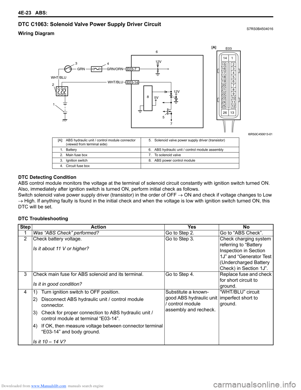
DTC C1063: Solenoid Valve Power Supply Driver CircuitS7RS0B4504016
Wiring Diagram
DTC Detecting Condition
ABS control module monitors the voltage at the terminal of solenoid circuit constantly with ignition switch turned ON.
Also, immediately after ignition switch is turned ON, perform initial check as follows.
Switch solenoid valve power supply driv er (transistor) in the order of OFF → ON and check if voltage changes to Low
→ High. If anything faulty is found in the initial check and when the voltage is low with ignition switch turned ON, this
DTC will be set.
DTC Troubleshooting
[A] E03
15
16
17
18
19
20
21
22
23
24
25 2
3
4
5
6
7
8
9
10
11
12
1
13
14
266
WHT/BLU
12V
5E03-14
5V
12V
8
GRN/ORNE03-7
WHT/BLU
GRN
1
2 3
4
7
I6RS0C450013-01
[A]: ABS hydraulic unit / control module connector
(viewed from terminal side) 5. Solenoid valve power supp
ly driver (transistor)
1. Battery 6. ABS hydraulic unit / control module assembly
2. Main fuse box 7. To solenoid valve
3. Ignition switch 8. ABS power control module
4. Circuit fuse box
Step Action YesNo
1 Was “ABS Check” performed? Go to Step 2.Go to “ABS Check”.
2 Check battery voltage.
Is it about 11 V or higher? Go to Step 3.
Check charging system
referring to “Battery
Inspection in Section
1J” and “Generator Test
(Undercharged Battery
Check) in Section 1J”.
3 Check main fuse for ABS solenoid and its terminal.
Is it in good condition? Go to Step 4.
Replace fuse and check
for short circuit to
ground.
4 1) Turn ignition switch to OFF position.
2) Disconnect ABS hydraulic unit / control module connector.
3) Check for proper connection to ABS hydraulic unit / control module at terminal “E03-14”.
4) If OK, then measure voltage between connector terminal “E03-14” and body ground.
Is it 10 – 14 V? Substitute a known-
good ABS hydraulic unit
/ control module
assembly and recheck.
“WHT/BLU” circuit
imperfect short to
ground.
Page 595 of 1496
Downloaded from www.Manualslib.com manuals search engine Electronic Stability Program: 4F-21
Stability control (ACTIVE, INACTIVE): This indicates
stability control in acti vation / deactivation.
TCS control (brake) ( ACTIVE, INACTIVE): This
indicates brake function of TCS in activation /
deactivation.
TCS control (engine) (ACTIVE, INACTIVE): This
indicates torque control of TCS in activation /
deactivation. ESP®
off state (cont) (ESP ® ON, ESP ® OFF): State
of ESP ® OFF switch.
Steering angle Sen (Neutral, NON newtral): This
indicates steering wheel angle measured by steering
angle sensor is in straight-ahead or not.
Visual InspectionS7RS0B4604059
Check the following parts and systems visually.
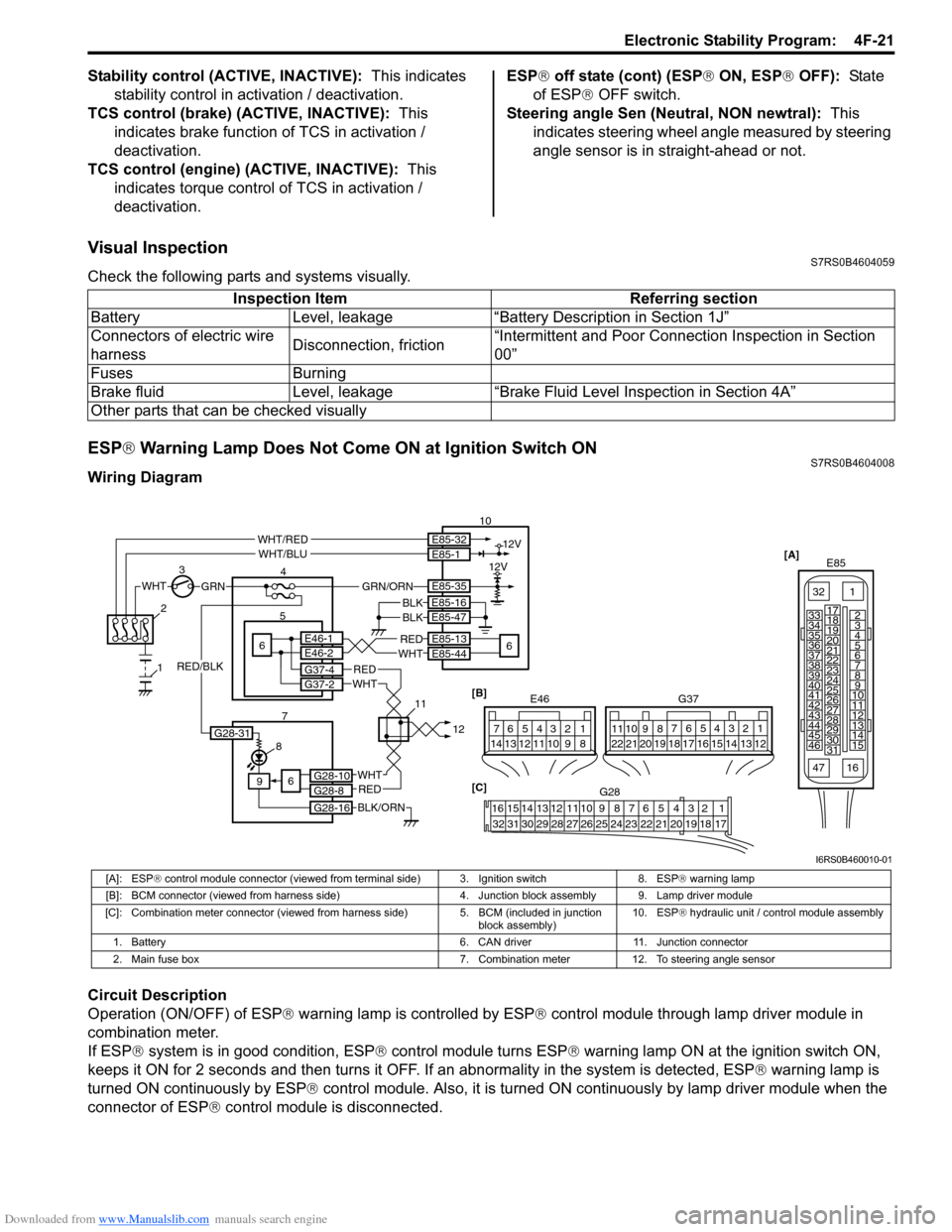
ESP ® Warning Lamp Does Not Come ON at Ignition Switch ONS7RS0B4604008
Wiring Diagram
Circuit Description
Operation (ON/OFF) of ESP ® warning lamp is controlled by ESP ® control module through lamp driver module in
combination meter.
If ESP ® system is in good condition, ESP ® control module turns ESP ® warning lamp ON at the ignition switch ON,
keeps it ON for 2 seconds and then turns it OFF. If an abnormality in the system is detected, ESP ® warning lamp is
turned ON continuously by ESP ® control module. Also, it is turned ON continuously by lamp driver module when the
connector of ESP ® control module is disconnected.Inspection Item Referring section
Battery Level, leakage “Battery Description in Section 1J”
Connectors of electric wire
harness Disconnection, friction“Intermittent and Poor Connec
tion Inspection in Section
00”
Fuses Burning
Brake fluid Level, leakage “Brake Fluid Level Inspection in Section 4A”
Other parts that can be checked visually
[A] E85
161
15
2
3
4
5
6
7
8
9
10
11
12
13
14
17
18
19
20
21
22
23
24
25
26
27
28
29
30
31
3233
34
35
36
37
38
39
40
41
42
43
44
45
46
47
WHTGRN
3
E85-13
E85-44REDWHT6 5E46-1E46-2
4 10
6
E85-16
E85-47BLKBLK
8
9
BLK/ORN
REDWHT
REDWHT
G37-4G37-2
G28-10G28-8
G28-16
12V
12VE85-32E85-1
E85-35
WHT/REDWHT/BLU
GRN/ORN
6
2
1
7 1112[B]
G37
E46124
53
67
891011121314124
53
67
891011
1213141516171819202122
[C] G28
12345678910111213141516
17181920212223242526272829303132
G28-31
RED/BLK
I6RS0B460010-01
[A]: ESP ® control module connector (viewed from terminal side) 3. Ignition switch 8. ESP ® warning lamp
[B]: BCM connector (viewed from harness side) 4. Junction block assembly 9. Lamp driver module
[C]: Combination meter connector (viewed from harness side) 5. BCM (included in junction
block assembly) 10. ESP
® hydraulic unit / control module assembly
1. Battery 6. CAN driver 11. Junction connector
2. Main fuse box 7. Combination meter 12. To steering angle sensor
Page 615 of 1496
Downloaded from www.Manualslib.com manuals search engine Electronic Stability Program: 4F-41
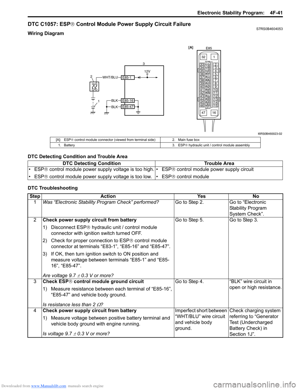
DTC C1057: ESP® Control Module Power Supply Circuit FailureS7RS0B4604053
Wiring Diagram
DTC Detecting Condition and Trouble Area
DTC Troubleshooting
[A]
E85
161
15
2
3
4
5
6
7
8
9
10
11
12
13
14
17
18
19
20
21
22
23
24
25
26
27
28
29
30
31
3233
34
35
36
37
38
39
40
41
42
43
44
45
46
47
WHT/BLU
1
2
3
12V
E85-1
BLKE85-16
E85-47BLK
I6RS0B460023-02
[A]: ESP
® control module connector (viewed from terminal side) 2. Main fuse box
1. Battery 3. ESP ® hydraulic unit / control module assembly
DTC Detecting Condition Trouble Area
• ESP ® control module power supply voltage is too high.
• ESP ® control module power supply voltage is too low. • ESP
® control module power supply circuit
• ESP ® control module
Step Action YesNo
1 Was “Electronic Stability Pr ogram Check” performed? Go to Step 2.Go to “Electronic
Stability Program
System Check”.
2 Check power supply circuit from battery
1) Disconnect ESP ® hydraulic unit / control module
connector with ignition switch turned OFF.
2) Check for proper connection to ESP ® control module
connector at terminals “E83-1”, “E85-16” and “E85-47”.
3) If OK, then turn ignition switch to ON position and measure voltage between terminals “E85-1” and “E85-
16”, “E85-47”.
Are voltage 9.7
± 0.3 V or more? Go to Step 5. Go to Step 3.
3 Check ESP ® control module ground circuit
1) Measure resistance between each terminal of “E85-16”, “E85-47” and vehicle body ground.
Is resistance less than 2
Ω? Go to Step 4. “BLK” wire circuit in
open or high resistance.
4 Check power supply circuit from battery
1) Measure voltage between positive battery terminal and
vehicle body ground with engine running.
Is voltage 9.7
± 0.3 V or more? Imperfect short between
“WHT/BLU” wire circuit
and vehicle body
ground.
Check charging system
referring to “Generator
Test (Undercharged
Battery Check) in
Section 1J”.
Page 616 of 1496
Downloaded from www.Manualslib.com manuals search engine 4F-42 Electronic Stability Program:
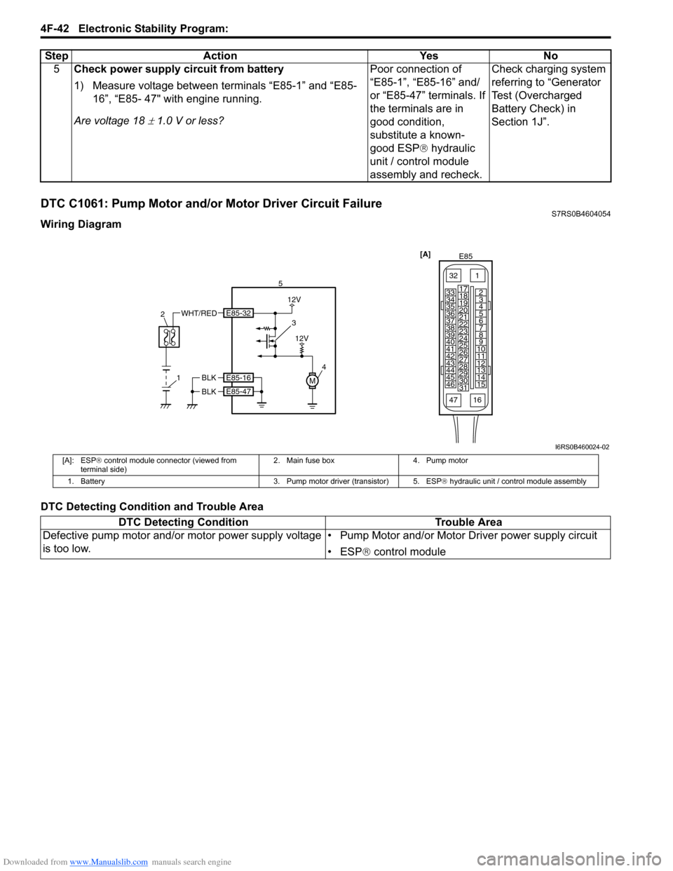
DTC C1061: Pump Motor and/or Motor Driver Circuit FailureS7RS0B4604054
Wiring Diagram
DTC Detecting Condition and Trouble Area5
Check power supply circuit from battery
1) Measure voltage between terminals “E85-1” and “E85-
16”, “E85- 47" with engine running.
Are voltage 18
± 1.0 V or less? Poor connection of
“E85-1”, “E85-16” and/
or “E85-47” terminals. If
the terminals are in
good condition,
substitute a known-
good ESP
® hydraulic
unit / control module
assembly and recheck. Check charging system
referring to “Generator
Test (Overcharged
Battery Check) in
Section 1J”.
Step Action Yes No
[A]
E85
161
15
2
3
4
5
6
7
8
9
10
11
12
13
14
17
18
19
20
21
22
23
24
25
26
27
28
29
30
31
3233
34
35
36
37
38
39
40
41
42
43
44
45
46
47
4
51
2
WHT/RED3
12V
M
12V
BLK
BLK
E85-16
E85-47
E85-32
I6RS0B460024-02
[A]: ESP
® control module connector (viewed from
terminal side) 2. Main fuse box 4. Pump motor
1. Battery 3. Pump motor driver (transistor) 5. ESP® hydraulic unit / control module assembly
DTC Detecting ConditionTrouble Area
Defective pump motor and/or motor power supply voltage
is too low. • Pump Motor and/or Motor Driver power supply circuit
• ESP
® control module
Page 618 of 1496
Downloaded from www.Manualslib.com manuals search engine 4F-44 Electronic Stability Program:
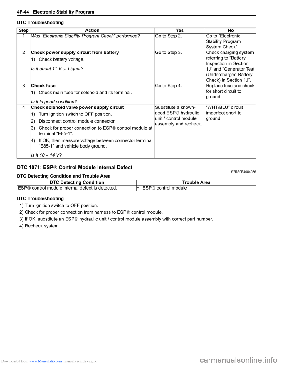
DTC Troubleshooting
DTC 1071: ESP® Control Module Internal DefectS7RS0B4604056
DTC Detecting Condition and Trouble Area
DTC Troubleshooting
1) Turn ignition switch to OFF position.
2) Check for proper connection from harness to ESP ® control module.
3) If OK, substitute an ESP ® hydraulic unit / control module assembly with correct part number.
4) Recheck system.
Step
Action YesNo
1 Was “Electronic Stability Pr ogram Check” performed? Go to Step 2.Go to “Electronic
Stability Program
System Check”.
2 Check power supply circuit from battery
1) Check battery voltage.
Is it about 11 V or higher? Go to Step 3.
Check charging system
referring to “Battery
Inspection in Section
1J” and “Generator Test
(Undercharged Battery
Check) in Section 1J”.
3 Check fuse
1) Check main fuse for solenoid and its terminal.
Is it in good condition? Go to Step 4.
Replace fuse and check
for short circuit to
ground.
4 Check solenoid valve power supply circuit
1) Turn ignition switch to OFF position.
2) Disconnect control module connector.
3) Check for proper connection to ESP® control module at
terminal “E85-1”.
4) If OK, then measure voltage between connector terminal “E85-1” and vehicle body ground.
Is it 10 – 14 V? Substitute a known-
good ESP
® hydraulic
unit / control module
assembly and recheck. “WHT/BLU” circuit
imperfect short to
ground.
DTC Detecting Condition
Trouble Area
ESP ® control module internal defect is detected. • ESP ® control module
Page 662 of 1496

Downloaded from www.Manualslib.com manuals search engine 5A-18 Automatic Transmission/Transaxle:
Visual InspectionS7RS0B5104002
Visually check the following parts and systems.
Malfunction Indicator Lamp (MIL) CheckS7RS0B5104003
Refer to the same item in “Malfunction Indicator Lam p (MIL) Check in Section 1A” for checking procedure.
Transmission Warning Light CheckS7RS0B5104004
1) Turn ignition switch ON.
2) Check that transmission warning light lights for about 2 – 4 sec. and then goes OFF.
If anything faulty is found, advance “Transmission Warn ing Light Circuit Check – Light Does Not Come “ON” at
Ignition Switch ON” or “Transmission Warning Light Circu it Check – Light Remains “ON” at Ignition Switch ON”.
Inspection item Referring
• A/T fluid ----- level, leakage, color “Automatic Transaxle Fluid Level Inspection in Section 0B”
• A/T fluid hoses ----- disconnection, looseness, deterioration “A/T Fluid Cooler Hoses Replacement”
• A/T select cable ----- installation “S elect Cable Removal and Installation”
• Engine oil ----- level, leakage “Engine Oil and Filter Change in Section 0B”
• Engine coolant ----- level, leakage “Engine Coolant Change in Section 0B”
• Engine mountings ----- play, looseness, damage “Engine Assembly Removal and Installation in Section 1D”
• Suspension ----- play, looseness “Suspension, Wheels and Tires Symptom Diagnosis in Section 2A”
• Drive shafts ----- damage “Front Drive Shaft Assembly On-Vehicle Inspection in Section 3A”
• Battery ----- indicator condition, corrosion of terminal “Battery Inspection in Section 1J”
• Connectors of electric wire harness ----- disconnection, friction “Electronic Shift Control System Components
Location”
• Fuses ----- burning
• Parts ----- installation, damage
• Bolts ----- looseness
• Other parts that can be checked visually
Also check the following items at engine start, if possible.
• Transmission warning light (if equipped) ----- Operation “Transmission Warning Light Check”
• Malfunction indicator lamp ----- Operation “Malfunction Indicator Lamp (MIL) Check”
• Charge warning lamp ----- Operation “Generator Symptom Diagnosis in Section 1J”
• Engine oil pressure warning lamp ----- Operation “Oil Pressure Warning Ligh t Symptom Diagnosis in
Section 9C”
• Engine coolant temp. meter ----- Operation “Engine Coolant Temperature (ECT) Meter
Symptom Diagnosis in Section 9C”
• Other parts that can be checked visually
I4RS0A510008-01