Engine lights SUZUKI SWIFT 2005 2.G Service User Guide
[x] Cancel search | Manufacturer: SUZUKI, Model Year: 2005, Model line: SWIFT, Model: SUZUKI SWIFT 2005 2.GPages: 1496, PDF Size: 34.44 MB
Page 191 of 1496
Downloaded from www.Manualslib.com manuals search engine Engine General Information and Diagnosis: 1A-141
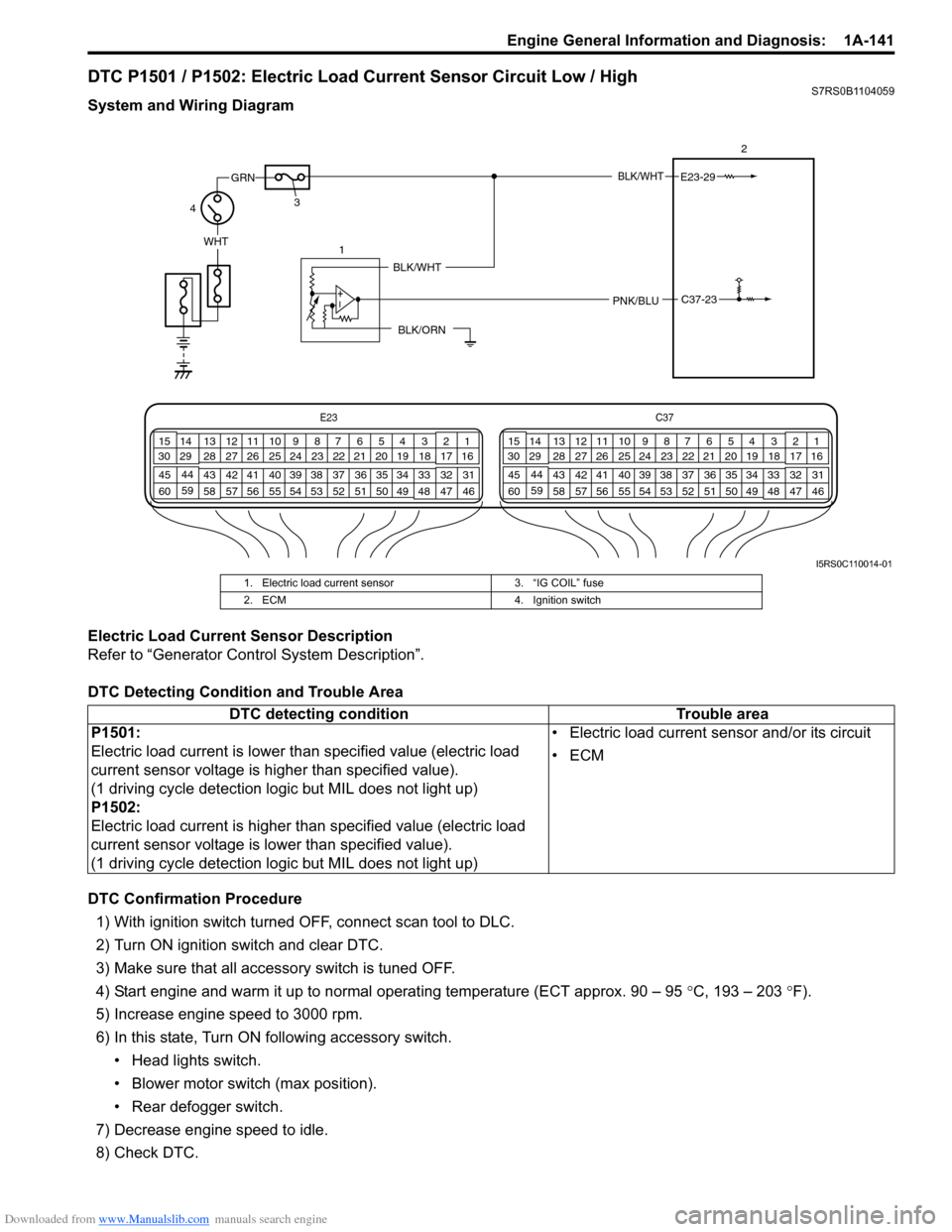
DTC P1501 / P1502: Electric Load Current Sensor Circuit Low / HighS7RS0B1104059
System and Wiring Diagram
Electric Load Current Sensor Description
Refer to “Generator Control System Description”.
DTC Detecting Condition and Trouble Area
DTC Confirmation Procedure1) With ignition switch turned OFF, connect scan tool to DLC.
2) Turn ON ignition switch and clear DTC.
3) Make sure that all accessory switch is tuned OFF.
4) Start engine and warm it up to normal operating temperature (ECT approx. 90 – 95 °C, 193 – 203 °F).
5) Increase engine speed to 3000 rpm.
6) In this state, Turn ON following accessory switch.
• Head lights switch.
• Blower motor switch (max position).
• Rear defogger switch.
7) Decrease engine speed to idle.
8) Check DTC.
E23 C37
34
1819
567
1011
17
20
47 46
495051
2122
52 16
25 9
24
14
29
55
57 54 53
59
60 58 2
262728
15
30
56 4832 31
34353637
40
42 39 38
44
45 43 41 331
1213
238
34
1819
567
1011
17
20
47 46
495051
2122
52 16
25 9
24
14
29
55
57 54 53
59
60 58 2
262728
15
30
56 4832 31
34353637
40
42 39 38
44
45 43 41 331
1213
238
BLK/WHT
WHT
GRN
4
3 2
E23-29
1
C37-23PNK/BLU
BLK/ORN
BLK/WHT
I5RS0C110014-01
1. Electric load current sensor
3. “IG COIL” fuse
2. ECM 4. Ignition switch
DTC detecting condition Trouble area
P1501:
Electric load current is lower th an specified value (electric load
current sensor voltage is higher than specified value).
(1 driving cycle detection logic but MIL does not light up)
P1502:
Electric load current is higher than specified value (electric load
current sensor voltage is lo wer than specified value).
(1 driving cycle detection logic but MIL does not light up) • Electric load current sensor and/or its circuit
•ECM
Page 266 of 1496
Downloaded from www.Manualslib.com manuals search engine 1A-216 Engine General Information and Diagnosis:
Repair Instructions
Idle Speed and IAC Throttle Valve Opening
Inspection
S7RS0B1106001
Before idle speed check, make sure of the following.
• Lead wires and hoses of electronic fuel injection and engine and emission control systems are connected
securely.
• Valve lash is checked according to maintenance schedule.
• Ignition timing is within specification.
• All accessories (wipers, heater, lights, A/C, etc.) are out of service.
• Air cleaner has been properly installed and is in good condition.
• No abnormal air drawn in from air intake system.
After all items are confirmed, check idle speed and IAC
duty as follows.
NOTE
Before starting engine, place transmission
gear shift lever in “Neutral” (shift selector
lever to “P” range for A/T vehicle), and set
parking brake and block drive wheels.
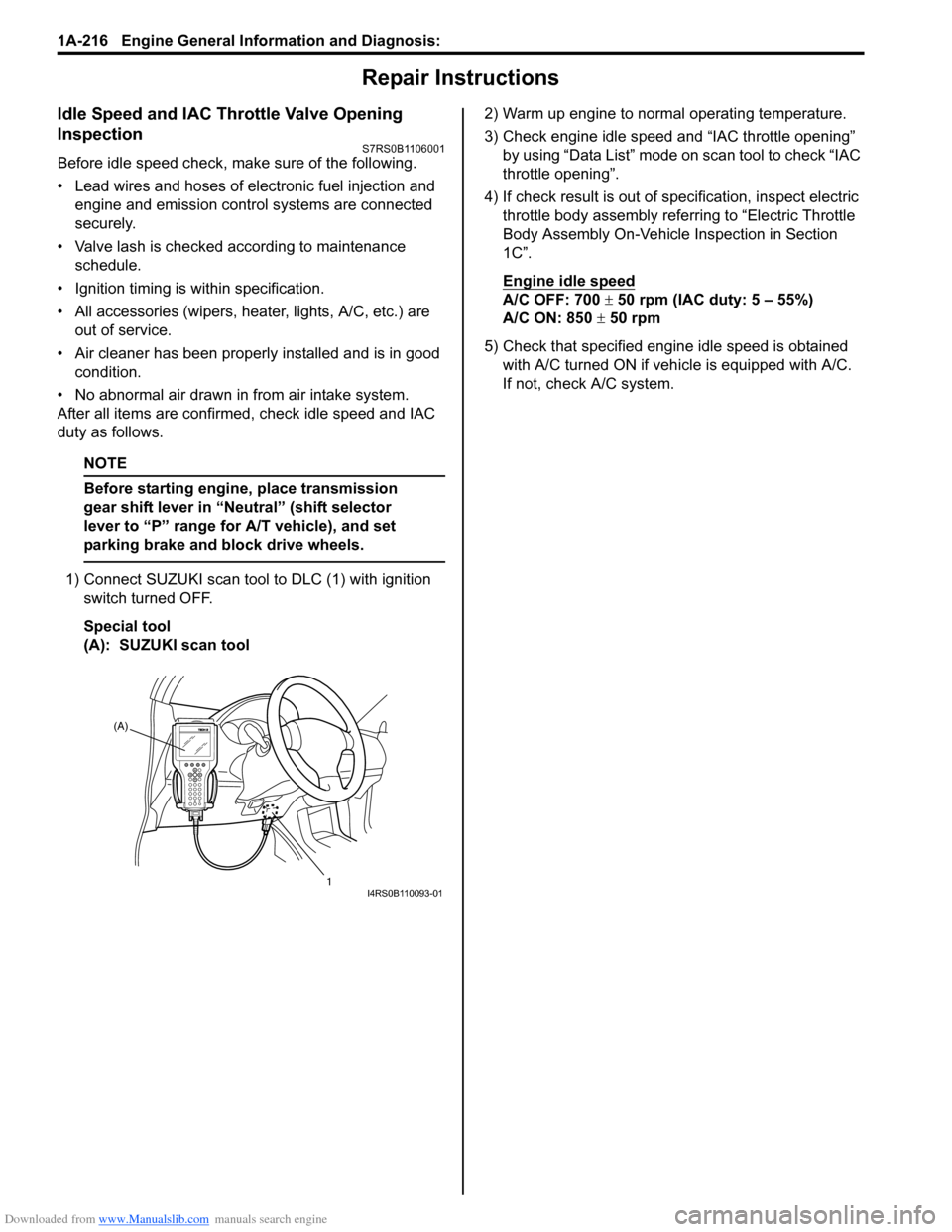
1) Connect SUZUKI scan tool to DLC (1) with ignition
switch turned OFF.
Special tool
(A): SUZUKI scan tool 2) Warm up engine to normal operating temperature.
3) Check engine idle speed and “IAC throttle opening”
by using “Data List” mode on scan tool to check “IAC
throttle opening”.
4) If check result is out of sp ecification, inspect electric
throttle body assembly referring to “Electric Throttle
Body Assembly On-Vehicle Inspection in Section
1C”.
Engine idle speed
A/C OFF: 700 ± 50 rpm (IAC duty: 5 – 55%)
A/C ON: 850 ± 50 rpm
5) Check that specified engine idle speed is obtained with A/C turned ON if vehi cle is equipped with A/C.
If not, check A/C system.
(A)
1
I4RS0B110093-01
Page 416 of 1496
Downloaded from www.Manualslib.com manuals search engine 1J-6 Charging System:
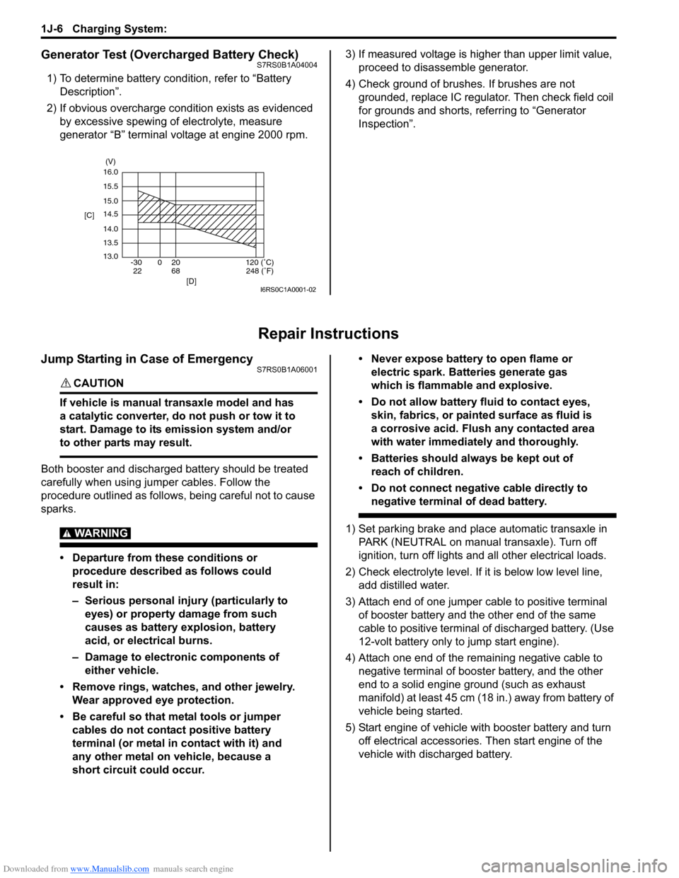
Generator Test (Overcharged Battery Check)S7RS0B1A04004
1) To determine battery condition, refer to “Battery Description”.
2) If obvious overcharge condition exists as evidenced by excessive spewing of electrolyte, measure
generator “B” terminal voltage at engine 2000 rpm. 3) If measured voltage is higher than upper limit value,
proceed to disassemble generator.
4) Check ground of brushes. If brushes are not grounded, replace IC regulator. Then check field coil
for grounds and shorts, referring to “Generator
Inspection”.
Repair Instructions
Jump Starting in Case of EmergencyS7RS0B1A06001
CAUTION!
If vehicle is manual transaxle model and has
a catalytic converter, do not push or tow it to
start. Damage to its emission system and/or
to other parts may result.
Both booster and discharged battery should be treated
carefully when using ju mper cables. Follow the
procedure outlined as follows, being careful not to cause
sparks.
WARNING!
• Departure from these conditions or procedure described as follows could
result in:
– Serious personal injury (particularly to eyes) or property damage from such
causes as battery explosion, battery
acid, or electrical burns.
– Damage to electronic components of either vehicle.
• Remove rings, watches, and other jewelry. Wear approved eye protection.
• Be careful so that metal tools or jumper cables do not contact positive battery
terminal (or metal in contact with it) and
any other metal on vehicle, because a
short circuit could occur. • Never expose battery to open flame or
electric spark. Batteries generate gas
which is flammable and explosive.
• Do not allow battery fluid to contact eyes, skin, fabrics, or painted surface as fluid is
a corrosive acid. Flush any contacted area
with water immediately and thoroughly.
• Batteries should always be kept out of reach of children.
• Do not connect negative cable directly to negative terminal of dead battery.
1) Set parking brake and place automatic transaxle in PARK (NEUTRAL on manual transaxle). Turn off
ignition, turn off lights and all other electrical loads.
2) Check electrolyte level. If it is below low level line, add distilled water.
3) Attach end of one jumper cable to positive terminal of booster battery and the other end of the same
cable to positive terminal of discharged battery. (Use
12-volt battery only to jump start engine).
4) Attach one end of the remaining negative cable to negative terminal of booster battery, and the other
end to a solid engine ground (such as exhaust
manifold) at least 45 cm (18 in.) away from battery of
vehicle being started.
5) Start engine of vehicle with booster battery and turn off electrical accessories. Then start engine of the
vehicle with discharged battery.
16.0
15.5
15.0
14.5
14.0
13.5
13.0 -30 0 20
[C]
[D]
68
22120 (˚C)
248 (˚F)
(V)
I6RS0C1A0001-02
Page 504 of 1496
Downloaded from www.Manualslib.com manuals search engine 4A-6 Brake Control System and Diagnosis:
Pedal pulsation (Pedal
pulsates when depressed
for braking)Damaged or loose wheel bearings
Replace wheel bearings.
Distorted steering knuckle or rear wheel
spindle Replace knuckle or rear wheel spindle.
Excessive disc lateral runout Check per instructions. If not within
specifications, replace or machine disc.
Parallelism between brake pad and disc
not within specifications Check per instructions. If not within
specifications, replace or machine disc.
Brake caliper piston sticking Repair as necessary.
Braking noise Worn or distorted brake pad Replace pads.
Loose front wheel bearings Replace wheel bearings.
Distorted backing plates or loose
mounting bolts Replace or retighten securing bolts.
Contact wear indicator to brake disc Replace brake pad.
Brake warning light lights
after engine start Parking brake applied
Release parking brake and check that brake
warning light turns off.
Insufficient amount of brake fluid Investigate leaky point, correct it and add
brake fluid.
Brake fluid leaking Investigate leaky point, correct it and add
brake fluid.
Brake warning light circuit faulty Repair circuit.
Malfunctioning EBD system Check system referring to “EBD Warning Light
(Brake Warning Light) Comes ON Steady in
Section 4E”.
Brake warning light turns
on when brake is applied Brake fluid leaking
Investigate leaky point, correct it and add
brake fluid.
Insufficient amount of brake fluid Investigate leaky point, correct it and add
brake fluid.
Brake warning light fails
to turn on even when
parking brake is applied Brake warning light circuit faulty
Replace bulb or repair circuit.
ABS warning light or
ESP
® warning light turns
on after engine start Malfunctioning ABS (ESP
®) Check system referri ng to “ABS Check in
Section 4E” or “Electronic Stability Program
System Check in Section 4F”.
ABS warning light or
ESP
® warning light turns
on when brake is applied Malfunctioning ABS (ESP
®) Check system referri ng to “ABS Check in
Section 4E” or “Electronic Stability Program
System Check in Section 4F”.
ABS warning light or
ESP
® warning light does
not turn on for 2 sec. after
ignition switch has turned
ON Bulb burnt out
Replace bulb.
Malfunctioning ABS (ESP ®) Check system referri ng to “ABS Check in
Section 4E” or “Electronic Stability Program
System Check in Section 4F”.
ABS warning light flashes New ABS hydraulic unit / control module
assembly installed. Perform “ABS Hydraulic
Unit Operation Check
in Section 4E”.
Condition Possible cause Correction / Reference Item
Page 506 of 1496
Downloaded from www.Manualslib.com manuals search engine 4A-8 Brake Control System and Diagnosis:
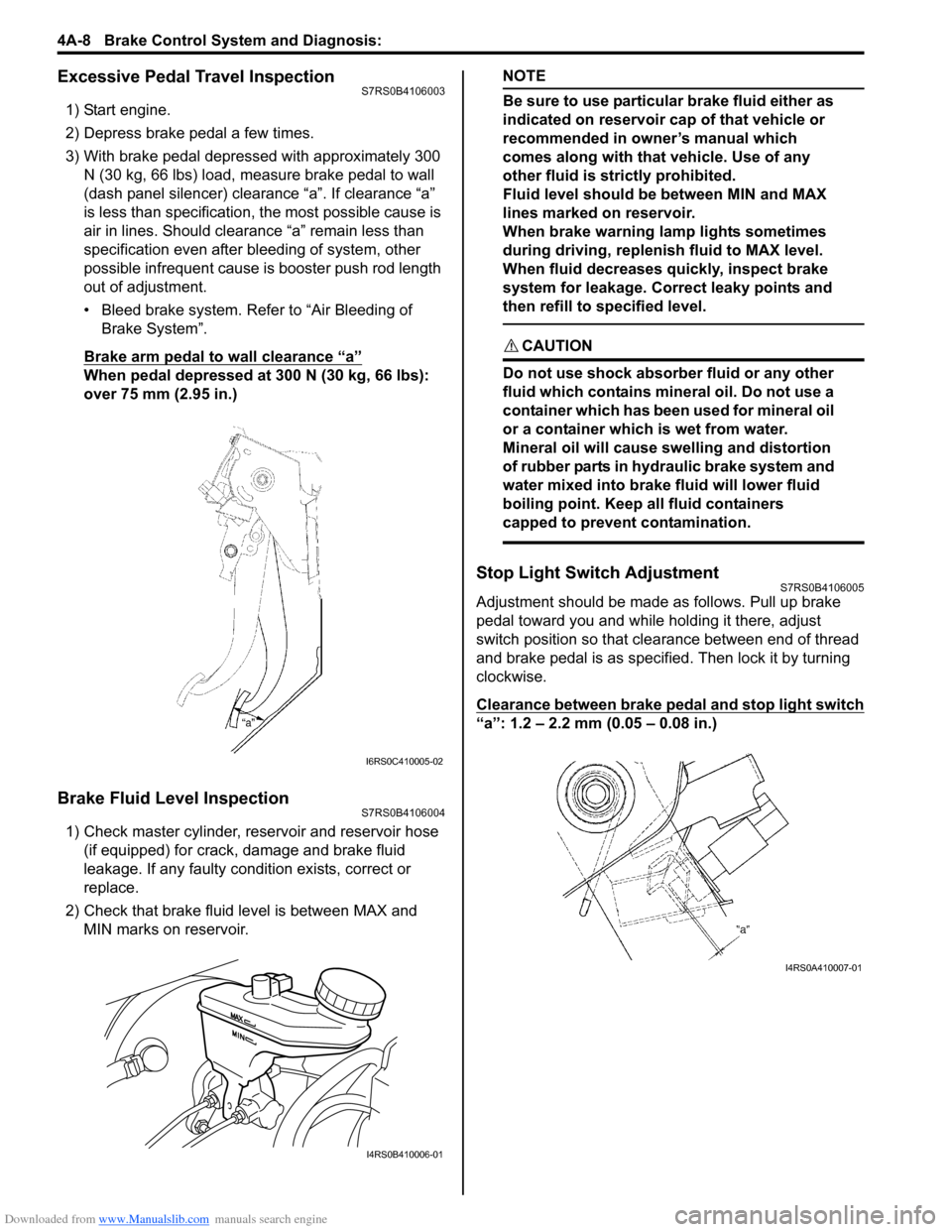
Excessive Pedal Travel InspectionS7RS0B4106003
1) Start engine.
2) Depress brake pedal a few times.
3) With brake pedal depressed with approximately 300 N (30 kg, 66 lbs) load, measure brake pedal to wall
(dash panel silencer) clearance “a”. If clearance “a”
is less than specification, the most possible cause is
air in lines. Should clearance “a” remain less than
specification even after bleeding of system, other
possible infrequent cause is booster push rod length
out of adjustment.
• Bleed brake system. Refer to “Air Bleeding of Brake System”.
Brake arm pedal to wall clearance “a”
When pedal depressed at 300 N (30 kg, 66 lbs):
over 75 mm (2.95 in.)
Brake Fluid Level InspectionS7RS0B4106004
1) Check master cylinder, reservoir and reservoir hose (if equipped) for crack, damage and brake fluid
leakage. If any faulty condition exists, correct or
replace.
2) Check that brake fluid level is between MAX and MIN marks on reservoir.
NOTE
Be sure to use particular brake fluid either as
indicated on reservoir cap of that vehicle or
recommended in owner’s manual which
comes along with that vehicle. Use of any
other fluid is strictly prohibited.
Fluid level should be between MIN and MAX
lines marked on reservoir.
When brake warning lamp lights sometimes
during driving, replenis h fluid to MAX level.
When fluid decreases quickly, inspect brake
system for leakage. Correct leaky points and
then refill to specified level.
CAUTION!
Do not use shock absorber fluid or any other
fluid which contains mineral oil. Do not use a
container which has been used for mineral oil
or a container which is wet from water.
Mineral oil will cause swelling and distortion
of rubber parts in hydraulic brake system and
water mixed into brake fluid will lower fluid
boiling point. Keep all fluid containers
capped to prevent contamination.
Stop Light Switch AdjustmentS7RS0B4106005
Adjustment should be made as follows. Pull up brake
pedal toward you and while holding it there, adjust
switch position so that clea rance between end of thread
and brake pedal is as specified. Then lock it by turning
clockwise.
Clearance between brake pedal and stop light switch
“a”: 1.2 – 2.2 mm (0.05 – 0.08 in.)
I6RS0C410005-02
I4RS0B410006-01
I4RS0A410007-01
Page 541 of 1496
Downloaded from www.Manualslib.com manuals search engine ABS: 4E-2
General Description
ABS DescriptionS7RS0B4501001
The ABS (Antilock Brake System) controls the fluid
pressure applied to the wheel cylinder of each brake
from the master cylinder so that each wheel is not locked
even when hard braking is applied.
This ABS has also the following function.
While braking is applied, but before ABS control
becomes effective, braking force is distributed between
the front and rear so as to prevent the rear wheels from
being locked too early for better stability of the vehicle.
The main component parts of this ABS include the
following parts in addition to those of the conventional
brake system.
• Wheel speed sensor which senses revolution speed of each wheel and outputs its signal.
• ABS warning light which light s to inform abnormality
when system fails to operate properly.
• ABS hydraulic unit / cont rol module assembly is
incorporated ABS co ntrol module, ABS hydraulic unit
(actuator assembly), solenoid valve power supply
driver (transistor), solenoid valve driver (transistor),
pump motor driver (transistor).
– ABS control module which sends operation signal to ABS hydraulic unit to control fluid pressure
applied to each wheel cylinder based on signal
from each wheel speed sensor so as to prevent
wheel from locking.
– ABS hydraulic unit which operates according to signal from ABS control module to control fluid
pressure applied to wheel cylinder of each 4
wheels.
– Solenoid valve power supp ly driver (transistor)
which supplies power to solenoid valve in ABS
hydraulic unit.
– Solenoid valve driver (transistor) which controls each solenoid valves in ABS hydraulic unit.
– Pump motor driver (transistor) which supplies power to pump motor in ABS hydraulic unit.
This ABS is equipped with Electronic Brake force
Distribution (EBD) system that controls a fluid pressure
of rear wheels to best condition, which is the same
function as that of proportion ing valve, by the signal from
wheel sensor independently of change of load due to
load capacity and so on. An d if the EBD system fails to
operate properly, the brake warning light lights to inform
abnormality.
ABS Hydraulic Unit / Control Module Assembly
Description
S7RS0B4501002
ABS control module is a component of ABS hydraulic
unit / control module asse mbly and has the following
functions.
Self-Diagnosis Function
ABS control module diagnose s conditions of the system
component parts (whether or not there is any
abnormality) all the time and indicates the results
(warning of abnormality occurrence and DTC) through
the ABS warning light as described.
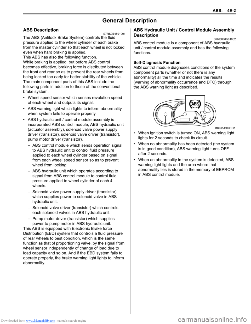
• When ignition switch is turned ON, ABS warning light lights for 2 seconds to check its circuit.
• When no abnormality has been detected (the system is in good condition), ABS warning light turns OFF
after 2 seconds.
• When an abnormality in th e system is detected, ABS
warning light lights and the area where that
abnormality lies is stored in the memory of EEPROM
in ABS control module.
1
I4RS0A450001-01
Page 549 of 1496
Downloaded from www.Manualslib.com manuals search engine ABS: 4E-10
Problem symptom confirmation
Check if what the customer claimed in “Customer
Questionnaire” is actually found in the vehicle and if that
symptom is found, whether it is identified as a failure.
(This step should be shared with the customer if
possible.) Check warning lights related to brake system
referring to “EBD Warning Light (Brake Warning Light)
Check” and “ABS Warning Light Check”.
DTC check, record and clearance
Perform “DTC Check” proced ure, record it and then
clear it referring to “DTC Clearance”.
Recheck DTC referring to “DTC Check”.
When DTC which is recorded at DTC check procedure is
detected again after performi ng DTC clearance, go to
“Step 4: ABS Check: ” to proceed the diagnosis.
When DTC which is recorded at DTC check procedure is
not indicated anymore after performing DTC clearance,
ABS control module does not perform the system
diagnosis, or temporary abnormality may occur,
therefore go to “Step 2: Driving Test: ” to proceed the
diagnosis.
Step 2: Driving Test
Test drive the vehicle at 40 km/h for more than a minute
and check if any trouble symptom (such as abnormal
lighting of ABS warn ing light) exists.
If the malfunction DTC is co nfirmed again at ignition
switch ON, driving test as described is not necessary.
Proceed to Step 3.
Step 3: DTC Check
Recheck DTC referring to “DTC Check”.
Step 4: ABS Check
According to ABS Check for the DTC confirmation in
Step 3, locate the cause of the trouble, namely in a
sensor, switch, wire harness, connector, actuator
assembly or other part and repair or replace faulty parts.
Step 5: Brakes Diagnosis
Check the parts or system suspected as a possible
cause referring to “Brakes Symptom Diagnosis in
Section 4A” and based on symptoms appearing on the
vehicle (symptom obtained through Steps 1 and 2 and
repair or replace faulty parts, if any).
Step 6: Check for Intermittent Problem
Check parts where an intermittent trouble is easy to
occur (e.g., wire harness, con nector, etc.), referring to
“Intermittent and Poor Connection Inspection in Section
00” and related circuit of trouble code recorded in Step 1
to 3.
Step 7: Final Confirmation Test
Confirm that the problem symptom has gone and the
ABS is free from any abnormal conditions. If what has
been repaired is related to the malfunction DTC, clear
the DTC once referring to “DTC Clearance” and perform
test driving and confirm that no DTC is indicated.ABS Warning Light CheckS7RS0B4504002
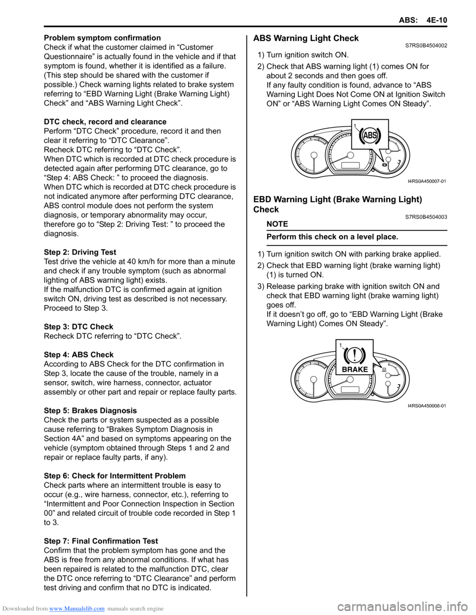
1) Turn ignition switch ON.
2) Check that ABS warning light (1) comes ON for
about 2 seconds and then goes off.
If any faulty condition is found, advance to “ABS
Warning Light Does Not Come ON at Ignition Switch
ON” or “ABS Warning Light Comes ON Steady”.
EBD Warning Light (Brake Warning Light)
Check
S7RS0B4504003
NOTE
Perform this check on a level place.
1) Turn ignition switch ON with parking brake applied.
2) Check that EBD warning lig ht (brake warning light)
(1) is turned ON.
3) Release parking brake with ignition switch ON and check that EBD warning lig ht (brake warning light)
goes off.
If it doesn’t go off, go to “EBD Warning Light (Brake
Warning Light) Comes ON Steady”.
11
I4RS0A450007-01
BRAKE
1
I4RS0A450008-01
Page 552 of 1496
Downloaded from www.Manualslib.com manuals search engine 4E-13 ABS:
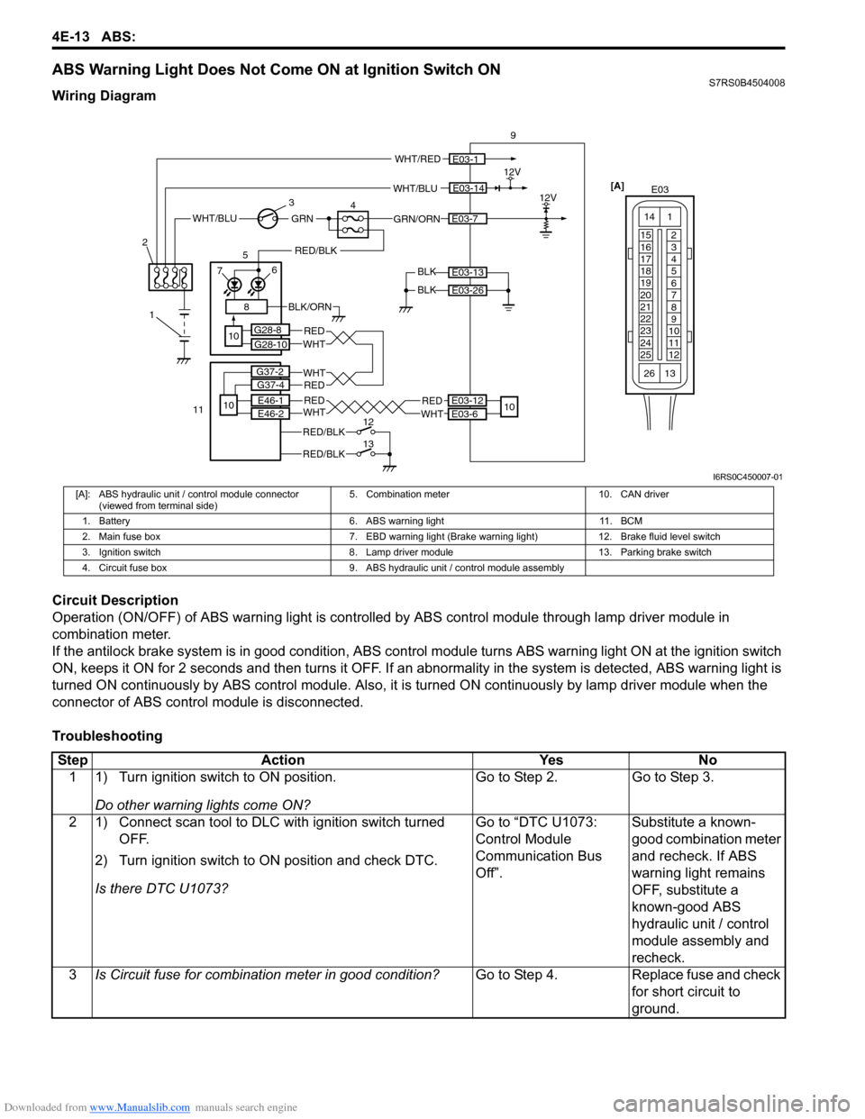
ABS Warning Light Does Not Come ON at Ignition Switch ONS7RS0B4504008
Wiring Diagram
Circuit Description
Operation (ON/OFF) of ABS warning light is controlled by ABS contro l module through lamp driver module in
combination meter.
If the antilock brake system is in good condition, ABS control module turns ABS warning light ON at the ignition switch
ON, keeps it ON for 2 seconds and then turns it OFF. If an abnormality in the system is detected, ABS warning light is
turned ON continuously by ABS control module. Also, it is turned ON continuously by la mp driver module when the
connector of ABS control module is disconnected.
Troubleshooting
WHT/BLU
BLK 12V
9
BLK
E03-14
E03-13
E03-26
WHT/RED
GRN/ORNE03-7WHT/BLUGRN
1
2
3
48
RED/BLK
76
5
10
E03-112V[A]
E03
15
16
17
18
19
20
21
22
23
24
25 2
3
4
5
6
7
8
9
10
11
12
1
13
14
26
BLK/ORN
E03-12
E03-6
REDWHT
10
G28-8
G28-10
REDWHTE46-1
E46-2
RED/BLK
RED/BLK
RED
RED
WHT
WHT
12
13
11
10
G37-2
G37-4
I6RS0C450007-01
[A]: ABS hydraulic unit / control module connector (viewed from terminal side) 5. Combination meter 10. CAN driver
1. Battery 6. ABS warning light 11. BCM
2. Main fuse box 7. EBD warning light (Brake warning light) 12. Brake fluid level switch
3. Ignition switch 8. Lamp driver module 13. Parking brake switch
4. Circuit fuse box 9. ABS hydraulic unit / control module assembly
Step Action YesNo
1 1) Turn ignition switch to ON position.
Do other warning lights come ON? Go to Step 2.
Go to Step 3.
2 1) Connect scan tool to DLC with ignition switch turned OFF.
2) Turn ignition switch to ON position and check DTC.
Is there DTC U1073? Go to “DTC U1073:
Control Module
Communication Bus
Off”.
Substitute a known-
good combination meter
and recheck. If ABS
warning light remains
OFF, substitute a
known-good ABS
hydraulic unit / control
module assembly and
recheck.
3 Is Circuit fuse fo r combination meter in good condition? Go to Step 4.Replace fuse and check
for short circuit to
ground.
Page 631 of 1496
Downloaded from www.Manualslib.com manuals search engine Electronic Stability Program: 4F-57
3) Remove front brake pipe referring to “Front Brake Hose / Pipe Removal and In stallation in Section 4A”.
4) Remove ESP ® hydraulic unit / control module with
bracket from vehicle by removing bracket bolts.
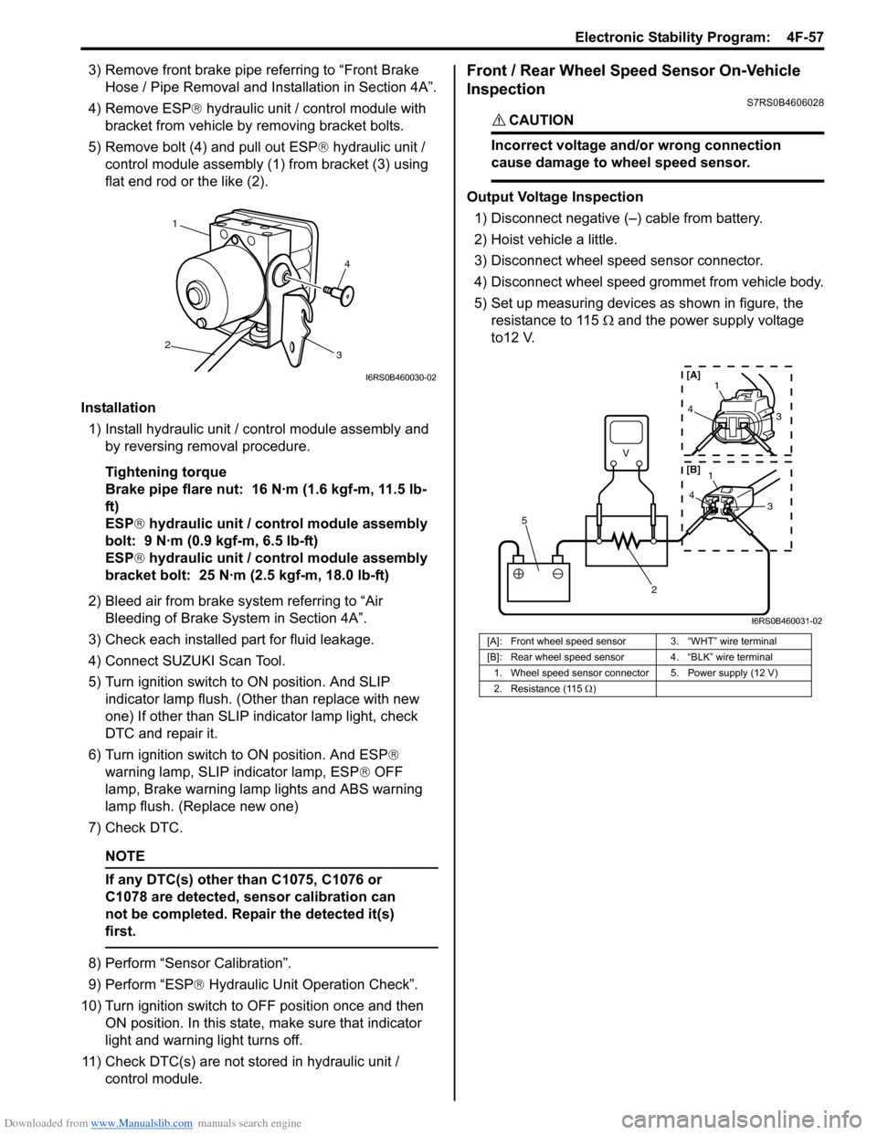
5) Remove bolt (4) and pull out ESP ® hydraulic unit /
control module assembly (1) from bracket (3) using
flat end rod or the like (2).
Installation 1) Install hydraulic unit / co ntrol module assembly and
by reversing removal procedure.
Tightening torque
Brake pipe flare nut: 16 N·m (1.6 kgf-m, 11.5 lb-
ft)
ESP ® hydraulic unit / control module assembly
bolt: 9 N·m (0.9 kgf-m, 6.5 lb-ft)
ESP ® hydraulic unit / control module assembly
bracket bolt: 25 N·m (2.5 kgf-m, 18.0 lb-ft)
2) Bleed air from brake system referring to “Air Bleeding of Brake System in Section 4A”.
3) Check each installed part for fluid leakage.
4) Connect SUZUKI Scan Tool.
5) Turn ignition switch to ON position. And SLIP indicator lamp flush. (Other than replace with new
one) If other than SLIP indicator lamp light, check
DTC and repair it.
6) Turn ignition switch to ON position. And ESP®
warning lamp, SLIP indicator lamp, ESP ® OFF
lamp, Brake warning lamp lights and ABS warning
lamp flush. (Replace new one)
7) Check DTC.
NOTE
If any DTC(s) other than C1075, C1076 or
C1078 are detected, sensor calibration can
not be completed. Repair the detected it(s)
first.
8) Perform “Sensor Calibration”.
9) Perform “ESP ® Hydraulic Unit Operation Check”.
10) Turn ignition switch to OFF position once and then
ON position. In this state, make sure that indicator
light and warning light turns off.
11) Check DTC(s) are not stored in hydraulic unit / control module.
Front / Rear Wheel Speed Sensor On-Vehicle
Inspection
S7RS0B4606028
CAUTION!
Incorrect voltage and/or wrong connection
cause damage to wheel speed sensor.
Output Voltage Inspection
1) Disconnect negative (–) cable from battery.
2) Hoist vehicle a little.
3) Disconnect wheel speed sensor connector.
4) Disconnect wheel speed grommet from vehicle body.
5) Set up measuring devices as shown in figure, the resistance to 115 Ω and the power supply voltage
to12 V.
4
1
2 3
I6RS0B460030-02
[A]: Front wheel speed sensor 3. “WHT” wire terminal
[B]: Rear wheel speed sensor 4. “BLK” wire terminal
1. Wheel speed sensor connector 5. Power supply (12 V)
2. Resistance (115 Ω)
V
2
5
4 1
3
43
1
[A]
[B]
I6RS0B460031-02
Page 645 of 1496
Downloaded from www.Manualslib.com manuals search engine Automatic Transmission/Transaxle: 5A-1
Transmission / Transaxle
Automatic Transmission/Transaxle
Precautions
Precautions in Diagnosing TroubleS7RS0B5100001
• Do not disconnect couplers from TCM, battery cable from battery, TCM ground wire harness from engine or
main fuse before checking the diagnostic information
(DTC, freeze frame data, etc.) stored in TCM memory.
Such disconnection will clea r memorized information
in TCM memory.
• Diagnostic information stored in TCM memory can be cleared as well as checked by using SUZUKI scan
tool or generic scan tool. Before using scan tool, read
its Operator’s (Instruction) Manual carefully to have
good understanding as to what functions are available
and how to use it.
It is indistinguishable wh ich module turns on MIL
because not only ECM but also TCM turns on MIL.
Therefore, check both ECM and TCM for DTC when
MIL lights on.
When checking TCM for DTC, keep in mind that DTC
is displayed on the scan tool as follows depending on
the scan tool used.
– SUZUKI scan tool displays DTC detected by TCM.
– Generic scan tool displays DTC detected by each of ECM and TCM simultaneously.
• Using SUZUKI scan tool the diagnostic information stored in TCM memory can be checked and cleared
as well. Before its use, be sure to read Operator’s
Manual supplied with it carefully to have good
understanding of its functions and usage.
• Be sure to read “Precautions for Electrical Circuit Service in Section 00” befo re inspection and observe
what is written there.
• TCM replacement
– When substituting a known-good TCM, check that all relays and actuators have resistance of
specified value.
Neglecting this check may result in damage to good
TCM.
• Communication of ECUs , ECM, TCM, ABS control
module, keyless start control module and BCM is
established by CAN (Controller Area Network).
Therefore, handle CAN communication line with care
referring to “Precaution for CAN Communication
System in Section 00”.
Precautions for Disassembly and ReassemblyS7RS0B5100002
When repairing automatic transaxle, it is necessary to
conduct the on-vehicle test to investigate where the
cause of the trouble lies first.
Then whether overhaul should be done or not is
determined. If the transaxle is disassembled without
such preliminary procedure, not only the cause of the
trouble would be unknown, but also a secondary trouble
may occur and often time would be wasted.
As the automatic transaxle consists of high precision
component, the following cautions should be strictly
observed when handling its parts in disassembly and
reassembly.
• Disassembling valve body assembly is prohibited
essentially. However, a few parts can be
disassembled. When disassembling valve body
component parts, confirm whether their parts are
allowed to disassemble or not referring to “Valve Body
Assembly Disassembly and Reassembly”.
• When component part of forward clutch, direct clutch, 2nd brake and/or O/D and 2nd coast brake, namely
clutch disc, brake disc, retaining plate and/or
separator plate, have been replaced, all learned
contents, which have been stored in TCM memory by
executing learning control, should be initialized
referring to “Learning Control Initialization”.
• Make sure to wash dirt off from the transaxle so that no such dirt will enter the transaxle during
dismounting and remounting.
• Select a clean place free from dust and dirt for overhauling.
• Place a rubber mat on the work bench to protect parts from damage.
• Work gloves or shop cloth should not be used. (Use a nylon cloth or a paper towel.)
• When separating the case joint, do not pry with a screwdriver or such but tap with a plastic hammer
lightly.
• Make sure to wash dirt off from the transaxle so that no such dirt will enter the transaxle during
disassembly and reassembly.
• Wash the disassembled parts in ATF (Automatic Transaxle Fluid) or kerosene (using care not to allow
ATF or kerosene to get on your face, etc.) and confirm
that each fluid passage is not clogged by blowing air
into it. But use kerosene to wash the discs, resin
washers and rubber parts.
• Replace each gasket, oil seal and O-ring with a new one.
• Apply ATF to sliding or rotating parts before
reassembly.