Wheel lug SUZUKI SWIFT 2005 2.G Service User Guide
[x] Cancel search | Manufacturer: SUZUKI, Model Year: 2005, Model line: SWIFT, Model: SUZUKI SWIFT 2005 2.GPages: 1496, PDF Size: 34.44 MB
Page 469 of 1496
Downloaded from www.Manualslib.com manuals search engine Wheels and Tires: 2D-2
Lower than recommended pressure can cause:
• Tire squeal on turns
• Hard Steering
• Rapid and uneven wear on the edges of the tread
• Tire rim bruises and rupture
• Tire cord breakage
• High tire temperature
• Reduced handling
• High fuel consumption
Replacement Tires
When replacement is necessary, the original equipment
type tire should be used. Refer to the Tire Placard.
Replacement tires should be of the same size, load
range and construction as those originally on the vehicle.
Use of any other size or type tire may affect ride,
handling, speedometer / odometer calibration, vehicle
ground clearance and tire or snow chain clearance to the
body and chassis.
It is recommended that new tires be installed in pairs on
the same axle. If necessary to replace only one tire, it
should be paired with the tire having the most tread, to
equalize braking traction.
WARNING!
Do not mix different types of tires on the
same vehicle such as radial, bias and bias-
belted tires except in emergencies, because
handling may be seriously affected and may
result in loss of control.
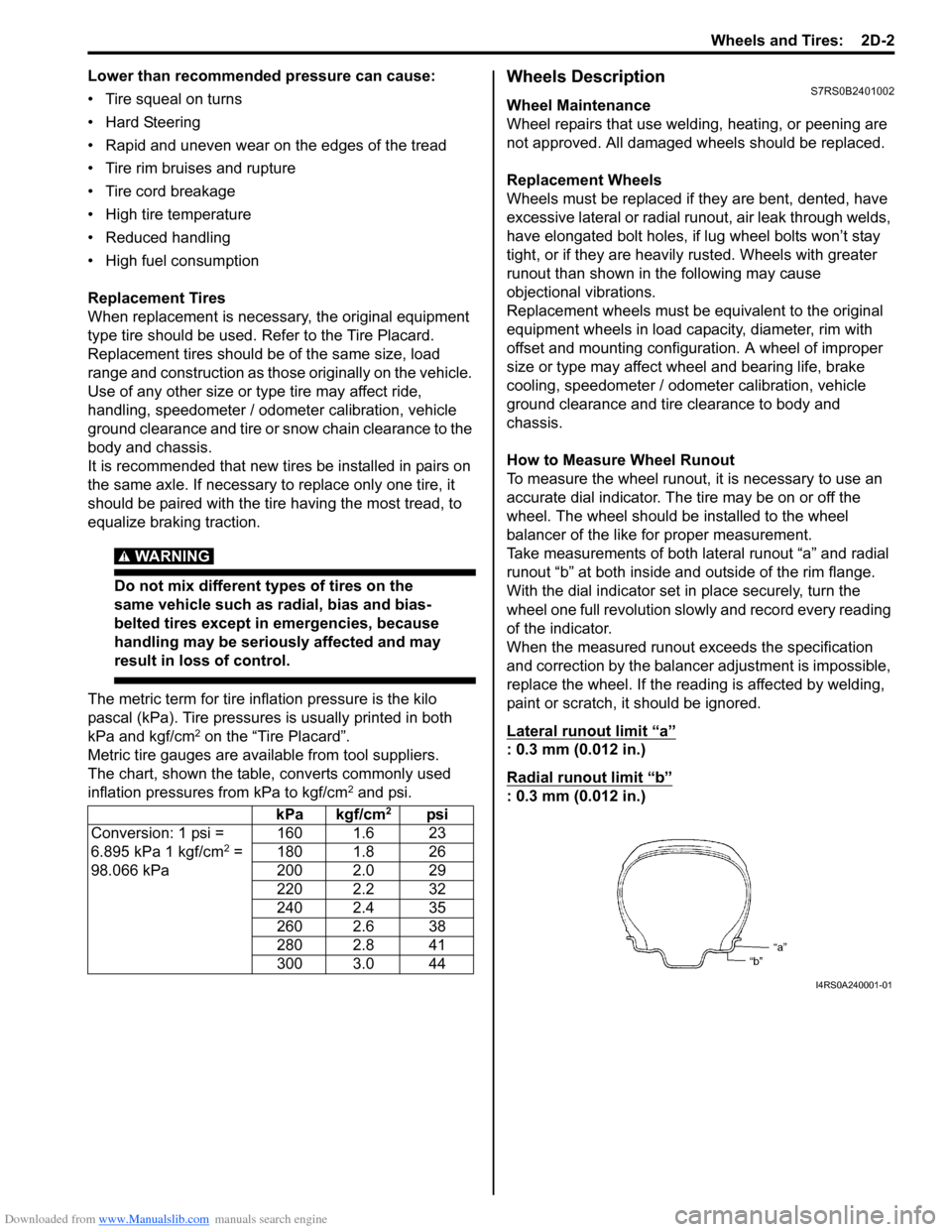
The metric term for tire infl ation pressure is the kilo
pascal (kPa). Tire pressures is usually printed in both
kPa and kgf/cm
2 on the “Tire Placard”.
Metric tire gauges are available from tool suppliers.
The chart, shown the table, converts commonly used
inflation pressures from kPa to kgf/cm
2 and psi.
Wheels DescriptionS7RS0B2401002
Wheel Maintenance
Wheel repairs that use welding, heating, or peening are
not approved. All damaged wheels should be replaced.
Replacement Wheels
Wheels must be replaced if they are bent, dented, have
excessive lateral or radial runout, air leak through welds,
have elongated bolt holes, if lug wheel bolts won’t stay
tight, or if they are heavily rusted. Wheels with greater
runout than shown in the following may cause
objectional vibrations.
Replacement wheels must be equivalent to the original
equipment wheels in load capacity, diameter, rim with
offset and mounting configuration. A wheel of improper
size or type may affect wheel and bearing life, brake
cooling, speedometer / odometer calibration, vehicle
ground clearance and tire clearance to body and
chassis.
How to Measure Wheel Runout
To measure the wheel runout, it is necessary to use an
accurate dial indicator. The tire may be on or off the
wheel. The wheel should be installed to the wheel
balancer of the like for proper measurement.
Take measurements of both lateral runout “a” and radial
runout “b” at both inside an d outside of the rim flange.
With the dial indicator set in place securely, turn the
wheel one full revolution slowly and record every reading
of the indicator.
When the measured runout exceeds the specification
and correction by the balancer adjustment is impossible,
replace the wheel. If the reading is affected by welding,
paint or scratch, it should be ignored.
Lateral runout limit “a”
: 0.3 mm (0.012 in.)
Radial runout limit “b”
: 0.3 mm (0.012 in.)
kPa kgf/cm2psi
Conversion: 1 psi =
6.895 kPa 1 kgf/cm
2 =
98.066 kPa 160 1.6 23
180 1.8 26
200 2.0 29
220 2.2 32
240 2.4 35
260 2.6 38
280 2.8 41
300 3.0 44
I4RS0A240001-01
Page 470 of 1496
Downloaded from www.Manualslib.com manuals search engine 2D-3 Wheels and Tires:
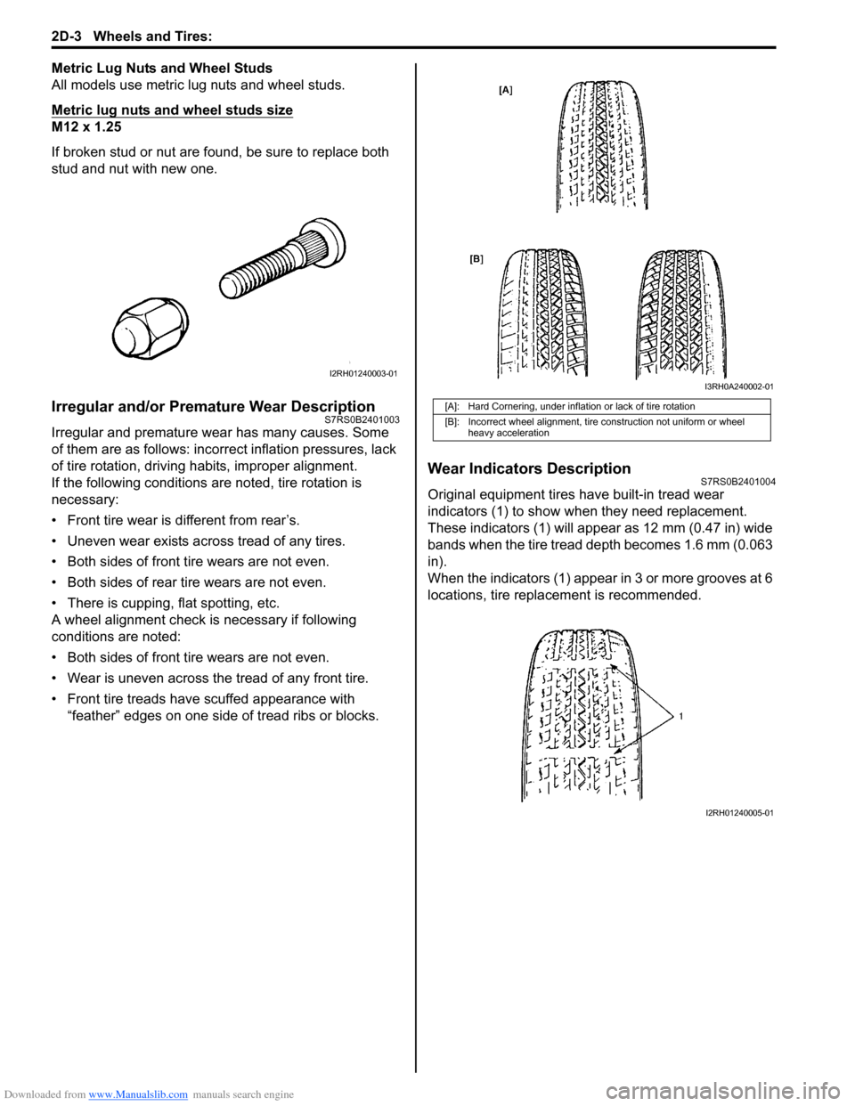
Metric Lug Nuts and Wheel Studs
All models use metric lug nuts and wheel studs.
Metric lug nuts and wheel studs size
M12 x 1.25
If broken stud or nut are found, be sure to replace both
stud and nut with new one.
Irregular and/or Premature Wear DescriptionS7RS0B2401003
Irregular and premature wear has many causes. Some
of them are as follows: incorrect inflation pressures, lack
of tire rotation, driving habits, improper alignment.
If the following conditions are noted, tire rotation is
necessary:
• Front tire wear is different from rear’s.
• Uneven wear exists across tread of any tires.
• Both sides of front tire wears are not even.
• Both sides of rear tire wears are not even.
• There is cupping, flat spotting, etc.
A wheel alignment check is necessary if following
conditions are noted:
• Both sides of front tire wears are not even.
• Wear is uneven across the tread of any front tire.
• Front tire treads have scuffed appearance with “feather” edges on one side of tread ribs or blocks.
Wear Indicators DescriptionS7RS0B2401004
Original equipment tires have built-in tread wear
indicators (1) to show when they need replacement.
These indicators (1) will app ear as 12 mm (0.47 in) wide
bands when the tire tread depth becomes 1.6 mm (0.063
in).
When the indicators (1) appear in 3 or more grooves at 6
locations, tire replacement is recommended.
I2RH01240003-01
[A]: Hard Cornering, under inflation or lack of tire rotation
[B]: Incorrect wheel alignment, tire construction not uniform or wheel heavy acceleration
I3RH0A240002-01
I2RH01240005-01
Page 475 of 1496
Downloaded from www.Manualslib.com manuals search engine Wheels and Tires: 2D-8
Tire Mounting and DismountingS7RS0B2406004
CAUTION!
When installing tire which has arrow
indicating tire rotation direction to wheel,
make sure that this tire rotation direction is
same as actual tire rotation direction when
vehicle is moving forward. Otherwise, it is
not possible to install wheel with tire to
vehicle in specified direction.
Use a tire changing machine to mount or dismount tires.
Follow equipment manufacturer’s instructions. Do not
use hand tools or tire irons al one to change tires as they
may damage tire beads or wheel rim.
Rim bead seats should be cleaned with a wire brush or
coarse steel wool to remove lubricants, old rubber and
light rust. Before mounting or dismounting a tire, bead
area should be well lubricated with approved tire
lubricant.
After mounting, inflate to specified pressure shown on
tire placard so that beads are completely seated.
WARNING!
Do not stand over tire when inflating. Bead
may break when bead snaps over rim’s safety
hump and cause serious personal injury.
Do not exceed 330 kpa (47.9 psi) pressure
when inflating. If 330 kpa (47.9 psi) pressure
will not seat beads, deflate, re-lubricate and
reinflate.
Over inflation may cause bead to break and
cause serious personal injury.
Install valve core and inflate to proper pressure.
Tire RepairS7RS0B2406005
There are many different materials and techniques on
the market to repair tires. As not all of these work on all
types of tires, tire manufacturers have published detailed
instructions on how and when to repair tires. These
instructions can be obtained from each tire
manufacturer.
Tire Repair for Emergency Repaired-Tire with
Sealant
S7RS0B2406006
WARNING!
Be sure to observe “Precaution for
Emergency Flat Tire Repair Kit”. Otherwise,
your health may be ruined.
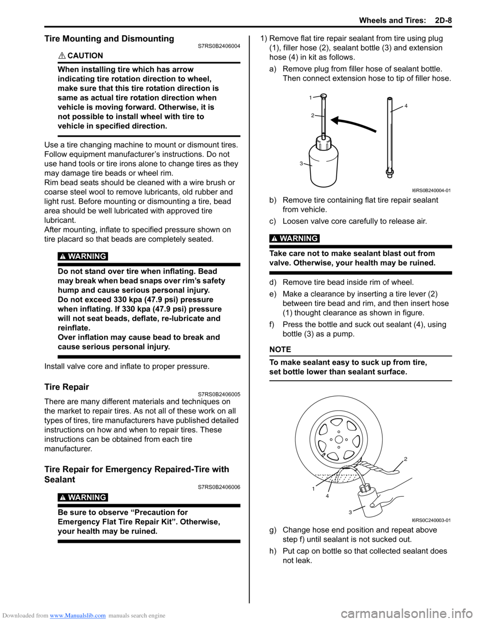
1) Remove flat tire repair sealant from tire using plug (1), filler hose (2), sealant bottle (3) and extension
hose (4) in kit as follows.
a) Remove plug from fille r hose of sealant bottle.
Then connect ext ension hose to tip of filler hose.
b) Remove tire containing flat tire repair sealant from vehicle.
c) Loosen valve core carefully to release air.
WARNING!
Take care not to make sealant blast out from
valve. Otherwise, your health may be ruined.
d) Remove tire bead inside rim of wheel.
e) Make a clearance by inserting a tire lever (2) between tire bead and rim, and then insert hose
(1) thought clearance as shown in figure.
f) Press the bottle and suck out sealant (4), using bottle (3) as a pump.
NOTE
To make sealant easy to suck up from tire,
set bottle lower than sealant surface.
g) Change hose end position and repeat above step f) until sealant is not sucked out.
h) Put cap on bottle so that collected sealant does not leak.
4
1
2
3
I6RS0B240004-01
1 4
3 2
I6RS0C240003-01
Page 503 of 1496
Downloaded from www.Manualslib.com manuals search engine Brake Control System and Diagnosis: 4A-5
If deterioration of rubber is evident, disassemble all
hydraulic parts and wash with alcohol. Dry these parts
with compressed air before assembly to keep alcohol out
of the system. Replace all rubber parts in the system,
including hoses. Also, when working on the brake
mechanisms, check for fluid on the linings.
If excessive fluid is found, replace the pads. If master cylinder piston seals
are satisfactory, check for
leakage or excessive heat co nditions. If leakage is not
found, drain fluid, flush with brake fluid, refill and bleed
system.
The system must be flushed if there is any doubt as to
the grade of fluid in the system or if fluid has been used
which contained parts that have been subjected to
contaminated fluid.
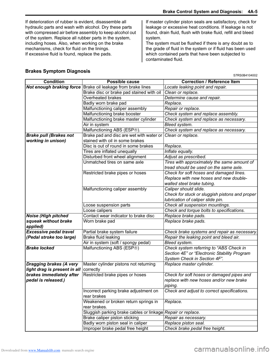
Brakes Symptom DiagnosisS7RS0B4104002
Condition Possible cause Correction / Reference Item
Not enough braking force Brake oil leakage from brake lines Locate leaking point and repair.
Brake disc or brake pad stained with oil Clean or replace.
Overheated brakes Determine cause and repair.
Badly worn brake pad Replace.
Malfunctioning caliper assembly Repair or replace.
Malfunctioning brake booster Check system and replace assembly.
Malfunctioning brake master cylinder Check system and replace as necessary.
Air in system Bleed system.
Malfunctioning ABS (ESP ®). Check system and replace as necessary.
Brake pull (Brakes not
working in unison) Brake pad and disc are wet with water or
stained with oil in some brakes Clean or replace.
Disc is out of round in some brakes Replace.
Tires are inflated unequally Inflate equally.
Disturbed front wheel alignment Adjust as prescribed.
Unmatched tires on same axle Tires with approximately the same amount of
tread should be used on the same axle.
Restricted brake pipes or hoses Check for soft hoses and damaged lines.
Replace with new hoses and new double-
walled steel brake tubing.
Malfunctioning caliper assembly Caliper should slide.
Check for stuck or sluggish pistons and proper
lubrication of caliper slide pin.
Loose suspension parts Check all suspension mountings.
Loose calipers Check and torque bolts to specifications.
Noise (High pitched
squeak without brake
applied) Contact wear indicator to brake disc
Replace brake pads.
Worn brake pad Replace brake pads.
Excessive pedal travel
(Pedal stroke too large) Partial brake system failure
Check brake systems and repair as necessary.
Brake fluid leaking Repair the leaking point and bleed air.
Air in system (soft / spongy pedal) Bleed system.
Brake locked Malfunctioning ABS (ESP®) Check system referri ng to “ABS Check in
Section 4E” or “Electronic Stability Program
System Check in Section 4F”.
Dragging brakes (A very
light drag is present in all
brakes immediately after
pedal is released.) Master cylinder pistons not returning
correctly
Replace master cylinder.
Restricted brake pipes or hoses Check for soft hoses or damaged pipes and
replace with new hoses and/or new brake
piping.
Incorrect parking brake adjustment on
rear brakes Check and adjust to correct specifications.
Weakened or broken return springs in
rear brakes. Replace.
Sluggish parking brake cables or linkage Repair or replace.
Brake caliper piston sticking Repair as necessary.
Badly worn piston seal in caliper Replace piston seal.
Improper brake pedal free height Check brake pedal free height.
Page 507 of 1496
Downloaded from www.Manualslib.com manuals search engine Brake Control System and Diagnosis: 4A-9
Air Bleeding of Brake SystemS7RS0B4106006
CAUTION!
Brake fluid is extremely damaging to paint. If
fluid should accidentally touch painted
surface, immediately wipe fluid from paint
and clean painted surface.
Bleeding operation is necessary to remove air whenever
it entered hydraulic brake system.
Hydraulic lines of brake system are based on the
diagonal split system. When a brake pipe or hose was
disconnected at the wheel, bleeding operation must be
performed at both ends of the line of the removed pipe or
hose. When any joint part of the master cylinder of other
joint part between the master cylinder and each brake
(wheel) was removed, the hydraulic brake system must
be bled at all 4 wheel brakes.
NOTE
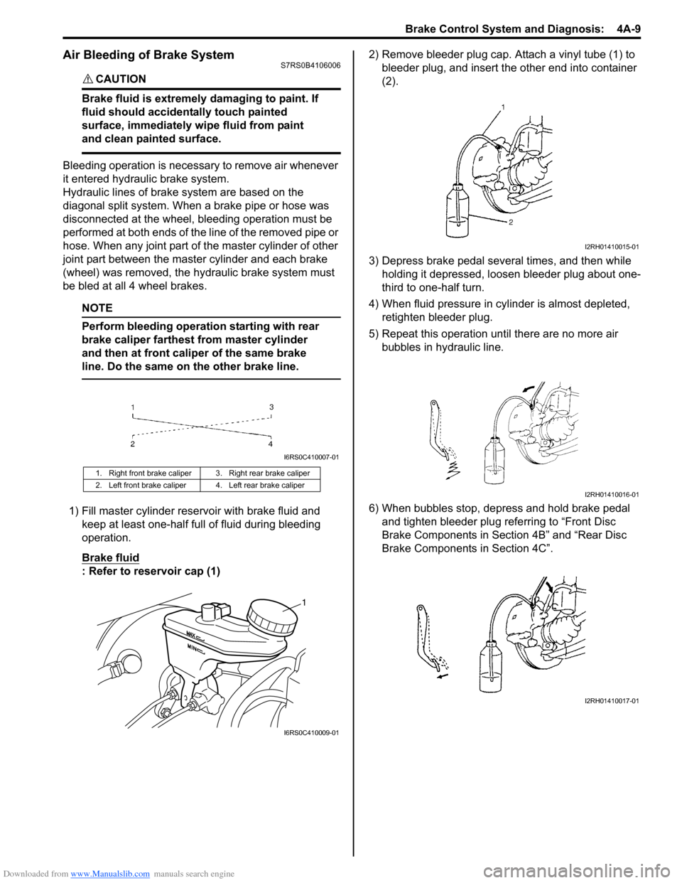
Perform bleeding operation starting with rear
brake caliper farthest from master cylinder
and then at front caliper of the same brake
line. Do the same on the other brake line.
1) Fill master cylinder rese rvoir with brake fluid and
keep at least one-half full of fluid during bleeding
operation.
Brake fluid
: Refer to reservoir cap (1) 2) Remove bleeder plug cap. Attach a vinyl tube (1) to
bleeder plug, and insert the other end into container
(2).
3) Depress brake pedal several times, and then while holding it depressed, loosen bleeder plug about one-
third to one-half turn.
4) When fluid pressure in cy linder is almost depleted,
retighten bleeder plug.
5) Repeat this operation until there are no more air bubbles in hydraulic line.
6) When bubbles stop, depress and hold brake pedal and tighten bleeder plug referring to “Front Disc
Brake Components in Section 4B” and “Rear Disc
Brake Components in Section 4C”.
1. Right front brake caliper 3. Right rear brake caliper
2. Left front brake caliper 4. Left rear brake caliper
I6RS0C410007-01
1
I6RS0C410009-01
I2RH01410015-01
I2RH01410016-01
I2RH01410017-01
Page 508 of 1496
Downloaded from www.Manualslib.com manuals search engine 4A-10 Brake Control System and Diagnosis:
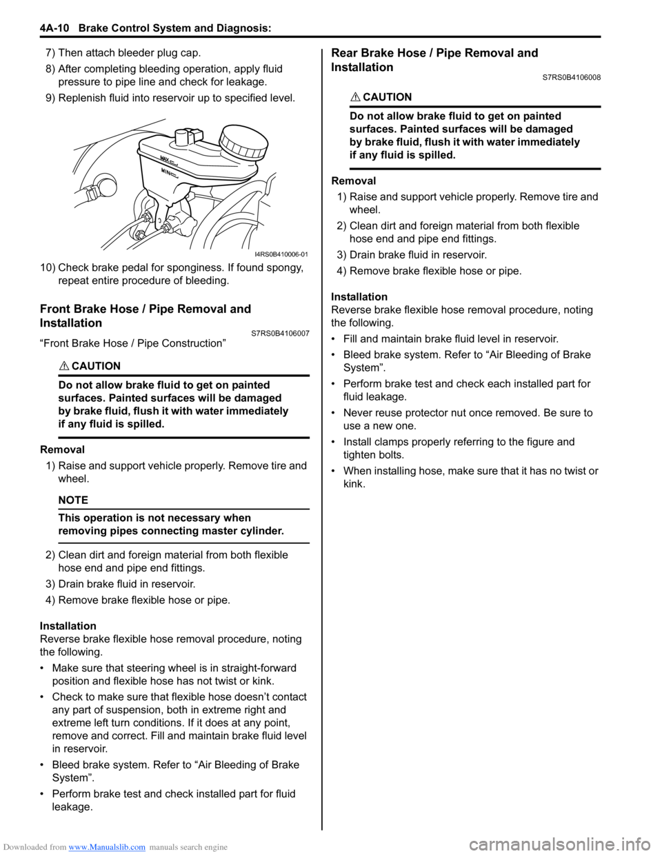
7) Then attach bleeder plug cap.
8) After completing bleeding operation, apply fluid pressure to pipe line and check for leakage.
9) Replenish fluid into reserv oir up to specified level.
10) Check brake pedal for sponginess. If found spongy, repeat entire procedure of bleeding.
Front Brake Hose / Pipe Removal and
Installation
S7RS0B4106007
“Front Brake Hose / Pipe Construction”
CAUTION!
Do not allow brake fluid to get on painted
surfaces. Painted surfaces will be damaged
by brake fluid, flush it with water immediately
if any fluid is spilled.
Removal
1) Raise and support vehicle properly. Remove tire and wheel.
NOTE
This operation is not necessary when
removing pipes connecting master cylinder.
2) Clean dirt and foreign mate rial from both flexible
hose end and pipe end fittings.
3) Drain brake fluid in reservoir.
4) Remove brake flexible hose or pipe.
Installation
Reverse brake flexible hose removal procedure, noting
the following.
• Make sure that steering wh eel is in straight-forward
position and flexible hose has not twist or kink.
• Check to make sure that flexible hose doesn’t contact any part of suspension, both in extreme right and
extreme left turn conditions. If it does at any point,
remove and correct. Fill and maintain brake fluid level
in reservoir.
• Bleed brake system. Refer to “Air Bleeding of Brake System”.
• Perform brake test and check installed part for fluid leakage.
Rear Brake Hose / Pipe Removal and
Installation
S7RS0B4106008
CAUTION!
Do not allow brake fluid to get on painted
surfaces. Painted surfaces will be damaged
by brake fluid, flush it with water immediately
if any fluid is spilled.
Removal
1) Raise and support vehicle properly. Remove tire and wheel.
2) Clean dirt and foreign material from both flexible hose end and pipe end fittings.
3) Drain brake fluid in reservoir.
4) Remove brake flexible hose or pipe.
Installation
Reverse brake flexible hose removal procedure, noting
the following.
• Fill and maintain brake fluid level in reservoir.
• Bleed brake system. Refer to “Air Bleeding of Brake System”.
• Perform brake test and check each installed part for fluid leakage.
• Never reuse protector nut once removed. Be sure to use a new one.
• Install clamps properly referring to the figure and tighten bolts.
• When installing hose, make sure that it has no twist or
kink.
I4RS0B410006-01
Page 520 of 1496
Downloaded from www.Manualslib.com manuals search engine 4B-4 Front Brakes:
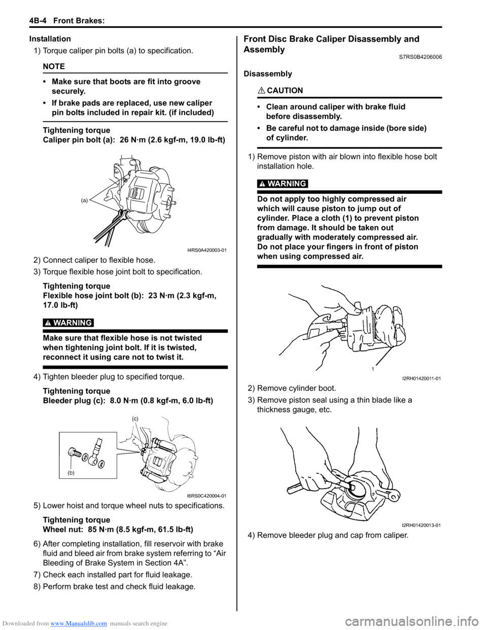
Installation1) Torque caliper pin bolts (a) to specification.
NOTE
• Make sure that boots are fit into groove securely.
• If brake pads are replaced, use new caliper pin bolts included in repair kit. (if included)
Tightening torque
Caliper pin bolt (a): 26 N·m (2.6 kgf-m, 19.0 lb-ft)
2) Connect caliper to flexible hose.
3) Torque flexible hose jo int bolt to specification.
Tightening torque
Flexible hose joint bolt (b): 23 N·m (2.3 kgf-m,
17.0 lb-ft)
WARNING!
Make sure that flexible hose is not twisted
when tightening joint bolt. If it is twisted,
reconnect it using care not to twist it.
4) Tighten bleeder plug to specified torque. Tightening torque
Bleeder plug (c): 8.0 N·m (0.8 kgf-m, 6.0 lb-ft)
5) Lower hoist and torque wheel nuts to specifications. Tightening torque
Wheel nut: 85 N·m (8.5 kgf-m, 61.5 lb-ft)
6) After completing installation, fill reservoir with brake
fluid and bleed air from brake system referring to “Air
Bleeding of Brake System in Section 4A”.
7) Check each installed part for fluid leakage.
8) Perform brake test and check fluid leakage.
Front Disc Brake Caliper Disassembly and
Assembly
S7RS0B4206006
Disassembly
CAUTION!
• Clean around caliper with brake fluid before disassembly.
• Be careful not to damage inside (bore side) of cylinder.
1) Remove piston with air blown into flexible hose bolt installation hole.
WARNING!
Do not apply too highly compressed air
which will cause piston to jump out of
cylinder. Place a cloth (1) to prevent piston
from damage. It should be taken out
gradually with moderately compressed air.
Do not place your fingers in front of piston
when using compressed air.
2) Remove cylinder boot.
3) Remove piston seal using a thin blade like a thickness gauge, etc.
4) Remove bleeder plug and cap from caliper.
(a)
I4RS0A420003-01
I6RS0C420004-01
I2RH01420011-01
I2RH01420013-01
Page 524 of 1496
Downloaded from www.Manualslib.com manuals search engine 4B-8 Front Brakes:
Specifications
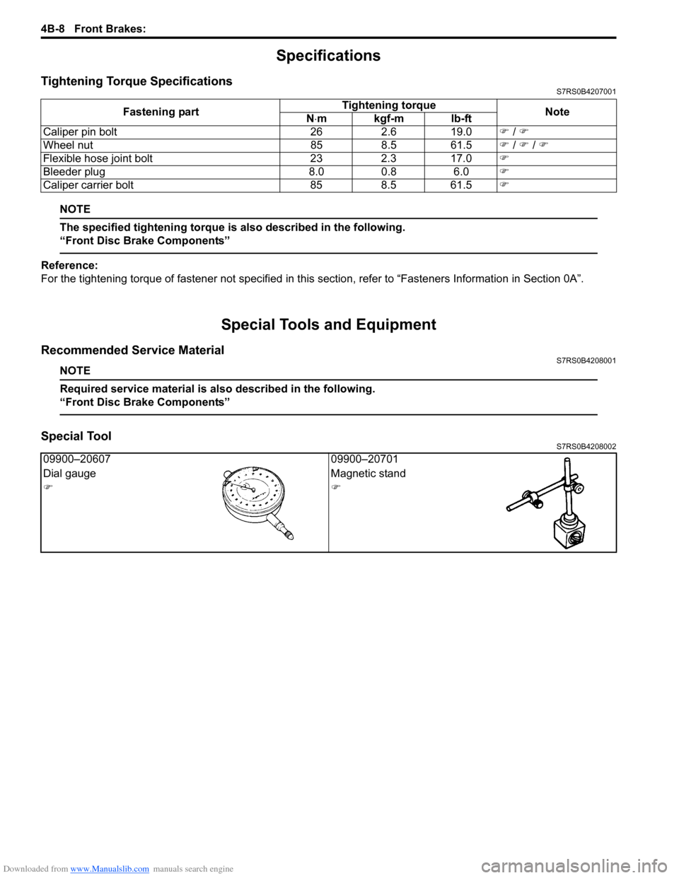
Tightening Torque SpecificationsS7RS0B4207001
NOTE
The specified tightening torque is also described in the following.
“Front Disc Brake Components”
Reference:
For the tightening torque of fastener not specified in this section, refer to “Fasteners Information in Section 0A”.
Special Tools and Equipment
Recommended Service MaterialS7RS0B4208001
NOTE
Required service material is also described in the following.
“Front Disc Brake Components”
Special ToolS7RS0B4208002
Fastening part Tightening torque
Note
N ⋅mkgf-mlb-ft
Caliper pin bolt 26 2.6 19.0 �) / �)
Wheel nut 85 8.5 61.5 �) / �) / �)
Flexible hose joint bolt 23 2.3 17.0 �)
Bleeder plug 8.0 0.8 6.0 �)
Caliper carrier bolt 85 8.5 61.5 �)
09900–2060709900–20701
Dial gauge Magnetic stand
�)�)
Page 527 of 1496
Downloaded from www.Manualslib.com manuals search engine Rear Brakes: 4C-3
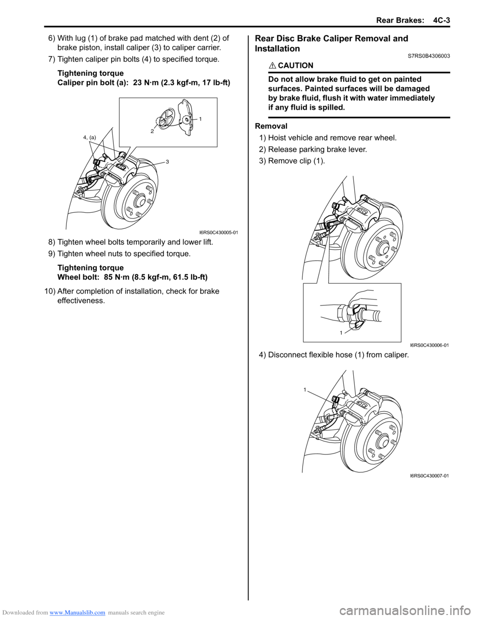
6) With lug (1) of brake pad matched with dent (2) of brake piston, install caliper (3) to caliper carrier.
7) Tighten caliper pin bolts (4) to specified torque.
Tightening torque
Caliper pin bolt (a): 23 N·m (2.3 kgf-m, 17 lb-ft)
8) Tighten wheel bolts temporarily and lower lift.
9) Tighten wheel nuts to specified torque. Tightening torque
Wheel bolt: 85 N·m (8.5 kgf-m, 61.5 lb-ft)
10) After completion of installation, check for brake effectiveness.Rear Disc Brake Caliper Removal and
Installation
S7RS0B4306003
CAUTION!
Do not allow brake fluid to get on painted
surfaces. Painted surfaces will be damaged
by brake fluid, flush it with water immediately
if any fluid is spilled.
Removal
1) Hoist vehicle and remove rear wheel.
2) Release parking brake lever.
3) Remove clip (1).
4) Disconnect flexible hose (1) from caliper.
4, (a) 21
3
I6RS0C430005-01
1
I6RS0C430006-01
1
I6RS0C430007-01
Page 544 of 1496
Downloaded from www.Manualslib.com manuals search engine 4E-5 ABS:
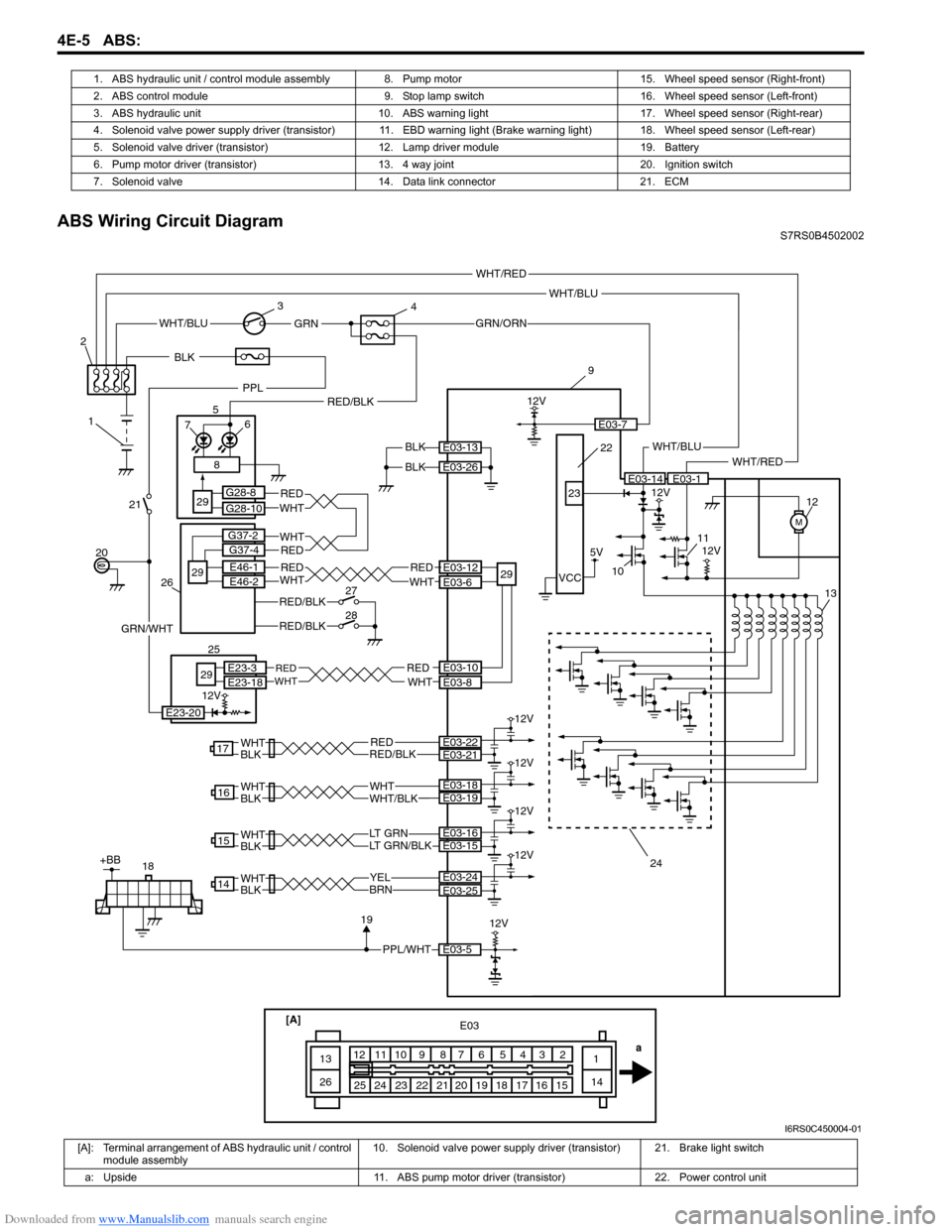
ABS Wiring Circuit DiagramS7RS0B4502002
1. ABS hydraulic unit / control module assembly 8.
Pump motor 15. Wheel speed sensor (Right-front)
2. ABS control module 9. Stop lamp switch 16. Wheel speed sensor (Left-front)
3. ABS hydraulic unit 10. ABS warning light 17. Wheel speed sensor (Right-rear)
4. Solenoid valve power supply driver (transistor) 11. EBD warnin g light (Brake warning light) 18. Wheel speed sensor (Left-rear)
5. Solenoid valve driver (transistor) 12. Lamp driver module 19. Battery
6. Pump motor driver (transistor) 13. 4 way joint 20. Ignition switch
7. Solenoid valve 14. Data link connector 21. ECM
[A]
14
1516171819202122232425 1
23456789101112
13
26 E03
a
WHT/BLU
BLKWHT/BLU
M
12V
9
10 11 12
13
BLKE03-14E03-1
E03-13
E03-26
YELBRN
14E03-24
LT GRN/BLKLT GRN
15
WHTWHT/BLK
16
RED
WHTBLK
WHTBLK
WHTBLK
WHTBLKRED/BLK
17
12V
PPL/WHT
18E03-5
1912V
5V
12V
23
24
VCC22
E03-25
E03-15E03-16
E03-19E03-18
E03-22E03-21
WHT/RED
WHT/RED
+BB
GRN/ORN
E03-7
WHT/BLUGRN
1
2
3
4
8
RED/BLK
E03-12
E03-6
RED
WHTE03-10E03-8
REDWHT
20 7
6
529
29
G28-8
G28-10
25
29
E23-3E23-18
GRN/WHT
21
PPL
12V
E23-20
12V
12V
12V
12V
REDWHTE46-1
E46-2
BLK
RED/BLK
RED/BLK
RED
RED
WHT
WHT
27
28
26
29
G37-2
G37-4
REDWHT
I6RS0C450004-01
[A]: Terminal arrangement of ABS hydraulic unit / control module assembly 10. Solenoid valve power supply driver
(transistor) 21. Brake light switch
a: Upside 11. ABS pump motor driver (transistor) 22. Power control unit