compressor check SUZUKI SWIFT 2005 2.G Service User Guide
[x] Cancel search | Manufacturer: SUZUKI, Model Year: 2005, Model line: SWIFT, Model: SUZUKI SWIFT 2005 2.GPages: 1496, PDF Size: 34.44 MB
Page 330 of 1496
Downloaded from www.Manualslib.com manuals search engine 1D-45 Engine Mechanical:
Pistons, Piston Rings, Connecting Rods and
Cylinders Removal and Installation
S7RS0B1406030
Removal1) Remove engine assembly from vehicle referring to тАЬEngine Assembly Removal and InstallationтАЭ.
2) Remove cylinder head referring to тАЬValves and Cylinder Head Removal and InstallationтАЭ.
3) Mark cylinder number on all pistons, connecting rods
and connecting rod caps using silver pencil or quick
drying paint.
4) Remove rod bearing caps.
5) Decarbonize top of cylinder bore before removing piston from cylinder.
6) Push piston and connecting rod assembly out through the top of cylinder bore.
Installation 1) Apply engine oil to pistons, rings, cylinder walls, connecting rod bearings and crank pins.
NOTE
Do not apply oil between connecting rod and
bearing or between bearing cap and bearing.
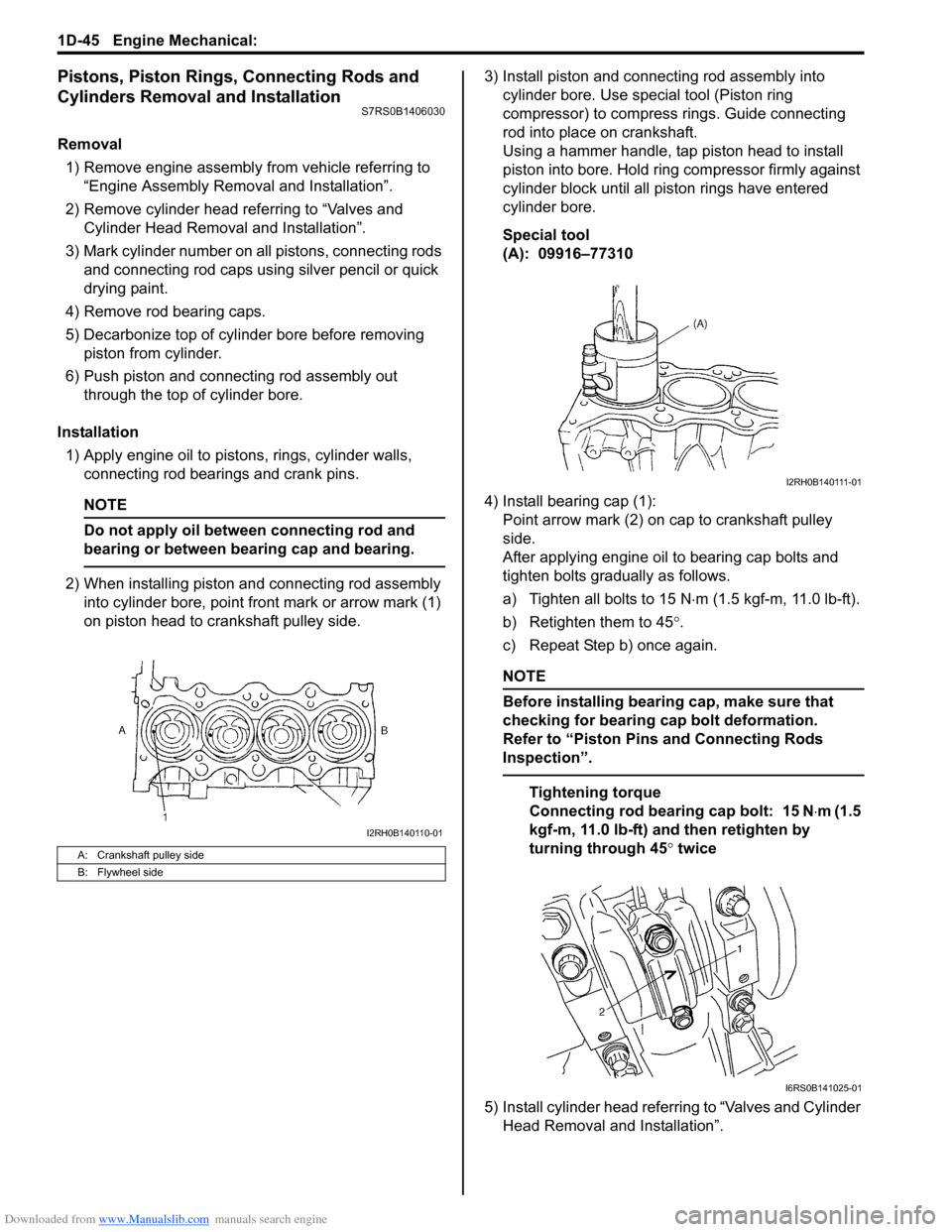
2) When installing piston and connecting rod assembly into cylinder bore, point front mark or arrow mark (1)
on piston head to crankshaft pulley side. 3) Install piston and connecting rod assembly into
cylinder bore. Use special tool (Piston ring
compressor) to compress rings. Guide connecting
rod into place on crankshaft.
Using a hammer handle, tap piston head to install
piston into bore. Hold ring compressor firmly against
cylinder block until all piston rings have entered
cylinder bore.
Special tool
(A): 09916тАУ77310
4) Install bearing cap (1): Point arrow mark (2) on cap to crankshaft pulley
side.
After applying engine oil to bearing cap bolts and
tighten bolts gradually as follows.
a) Tighten all bolts to 15 N тЛЕm (1.5 kgf-m, 11.0 lb-ft).
b) Retighten them to 45 ┬░.
c) Repeat Step b) once again.
NOTE
Before installing bearing cap, make sure that
checking for bearing cap bolt deformation.
Refer to тАЬPiston Pins and Connecting Rods
InspectionтАЭ.
Tightening torque
Connecting rod bearing cap bolt: 15 N тЛЕm (1.5
kgf-m, 11.0 lb-ft) and then retighten by
turning through 45 ┬░ twice
5) Install cylinder head referring to тАЬValves and Cylinder Head Removal and InstallationтАЭ.
A: Crankshaft pulley side
B: Flywheel side
I2RH0B140110-01
I2RH0B140111-01
I6RS0B141025-01
Page 371 of 1496
Downloaded from www.Manualslib.com manuals search engine Engine Cooling System: 1F-8
Thermostat Removal and InstallationS7RS0B1606007
Removal1) Drain coolant referring to тАЬCooling System DrainingтАЭ.
2) Remove intake manifold referring to тАЬIntake Manifold Removal and Installa tion in Section 1DтАЭ.
3) Remove generator referring to тАЬGenerator Dismounting and Remounting in Section 1JтАЭ.
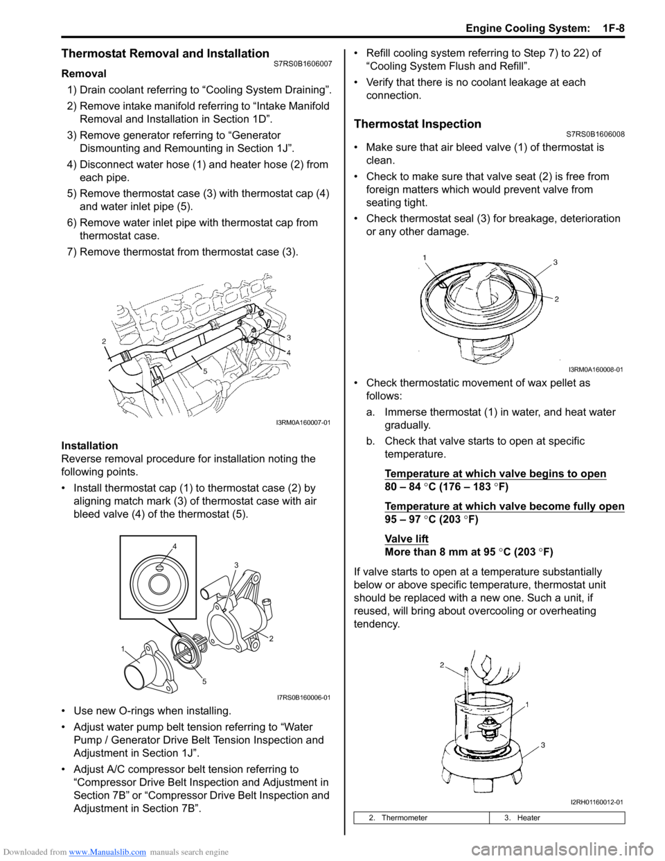
4) Disconnect water hose (1) and heater hose (2) from each pipe.
5) Remove thermostat case (3) with thermostat cap (4)
and water inlet pipe (5).
6) Remove water inlet pipe with thermostat cap from thermostat case.
7) Remove thermostat from thermostat case (3).
Installation
Reverse removal procedure for installation noting the
following points.
тАв Install thermostat cap (1) to thermostat case (2) by aligning match mark (3) of thermostat case with air
bleed valve (4) of the thermostat (5).
тАв Use new O-rings when installing.
тАв Adjust water pump belt tension referring to тАЬWater Pump / Generator Drive Belt Tension Inspection and
Adjustment in Section 1JтАЭ.
тАв Adjust A/C compressor belt tension referring to тАЬCompressor Drive Belt Inspection and Adjustment in
Section 7BтАЭ or тАЬCompressor Drive Belt Inspection and
Adjustment in Section 7BтАЭ. тАв Refill cooling system referrin
g to Step 7) to 22) of
тАЬCooling System Flush and RefillтАЭ.
тАв Verify that there is no coolant leakage at each connection.
Thermostat InspectionS7RS0B1606008
тАв Make sure that air bleed valve (1) of thermostat is clean.
тАв Check to make sure that va lve seat (2) is free from
foreign matters which would prevent valve from
seating tight.
тАв Check thermostat seal (3) for breakage, deterioration or any other damage.
тАв Check thermostatic movement of wax pellet as follows:
a. Immerse thermostat (1) in water, and heat water gradually.
b. Check that valve starts to open at specific temperature.
Temperature at which valve begins to open
80 тАУ 84 ┬░C (176 тАУ 183 ┬░F)
Temperature at which valve become fully open
95 тАУ 97 ┬░C (203 ┬░F)
Va l v e l i ft
More than 8 mm at 95 ┬░C (203 ┬░ F)
If valve starts to open at a temperature substantially
below or above specific temperature, thermostat unit
should be replaced with a new one. Such a unit, if
reused, will bring about ov ercooling or overheating
tendency.
I3RM0A160007-01
4
5 3
1 2
I7RS0B160006-01
2. Thermometer
3. Heater
I3RM0A160008-01
I2RH01160012-01
Page 374 of 1496
Downloaded from www.Manualslib.com manuals search engine 1F-11 Engine Cooling System:
Water Pump Removal and InstallationS7RS0B1606014
Removal1) Disconnect negative cable at battery.
2) Drain coolant.
3) Remove water pump / generator drive belt referring to тАЬWater Pump / Generator Drive Belt Removal and
Installation in Section 1JтАЭ.
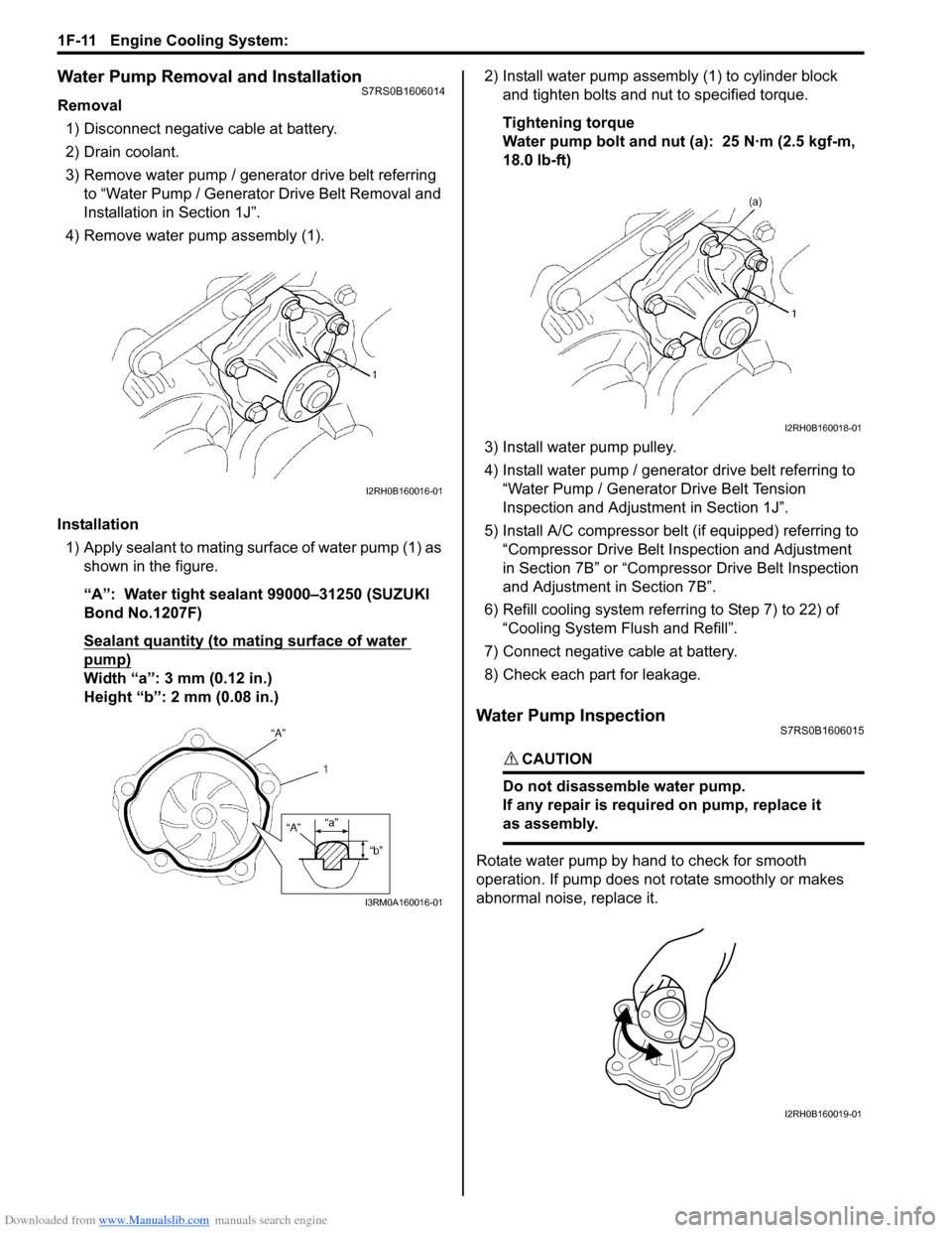
4) Remove water pump assembly (1).
Installation 1) Apply sealant to mating surface of water pump (1) as shown in the figure.
тАЬAтАЭ: Water tight sealant 99000тАУ31250 (SUZUKI
Bond No.1207F)
Sealant quantity (to mating surface of water
pump)
Width тАЬaтАЭ: 3 mm (0.12 in.)
Height тАЬbтАЭ: 2 mm (0.08 in.) 2) Install water pump assemb
ly (1) to cylinder block
and tighten bolts and nut to specified torque.
Tightening torque
Water pump bolt and nut (a): 25 N┬╖m (2.5 kgf-m,
18.0 lb-ft)
3) Install water pump pulley.
4) Install water pump / generator drive belt referring to тАЬWater Pump / Generator Drive Belt Tension
Inspection and Adjustment in Section 1JтАЭ.
5) Install A/C compressor belt (if equipped) referring to тАЬCompressor Drive Belt Inspection and Adjustment
in Section 7BтАЭ or тАЬCompressor Drive Belt Inspection
and Adjustment in Section 7BтАЭ.
6) Refill cooling system referri ng to Step 7) to 22) of
тАЬCooling System Flush and RefillтАЭ.
7) Connect negative cable at battery.
8) Check each part for leakage.
Water Pump InspectionS7RS0B1606015
CAUTION!
Do not disassemble water pump.
If any repair is requir ed on pump, replace it
as assembly.
Rotate water pump by hand to check for smooth
operation. If pump does not rotate smoothly or makes
abnormal noise, replace it.
I2RH0B160016-01
I3RM0A160016-01
I2RH0B160018-01
I2RH0B160019-01
Page 418 of 1496
Downloaded from www.Manualslib.com manuals search engine 1J-8 Charging System:
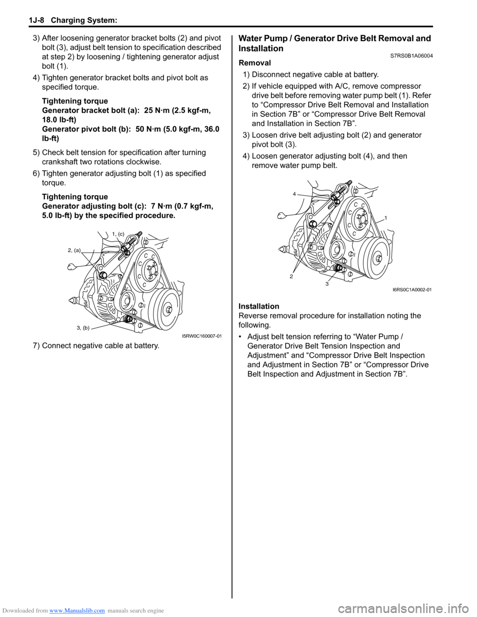
3) After loosening generator bracket bolts (2) and pivot bolt (3), adjust belt tensio n to specification described
at step 2) by loosening / tightening generator adjust
bolt (1).
4) Tighten generator bracket bolts and pivot bolt as specified torque.
Tightening torque
Generator bracket bolt (a): 25 N┬╖m (2.5 kgf-m,
18.0 lb-ft)
Generator pivot bolt (b): 50 N┬╖m (5.0 kgf-m, 36.0
lb-ft)
5) Check belt tension for specification after turning crankshaft two rotations clockwise.
6) Tighten generator adjusting bolt (1) as specified torque.
Tightening torque
Generator adjusting bolt (c): 7 N┬╖m (0.7 kgf-m,
5.0 lb-ft) by the specified procedure.
7) Connect negative cable at battery.Water Pump / Generator Drive Belt Removal and
Installation
S7RS0B1A06004
Removal 1) Disconnect negative cable at battery.
2) If vehicle equipped with A/C, remove compressor drive belt before removing water pump belt (1). Refer
to тАЬCompressor Drive Belt Removal and Installation
in Section 7BтАЭ or тАЬCompr essor Drive Belt Removal
and Installation in Section 7BтАЭ.
3) Loosen drive belt adjusting bolt (2) and generator pivot bolt (3).
4) Loosen generator adjusting bolt (4), and then remove water pump belt.
Installation
Reverse removal procedure for installation noting the
following.
тАв Adjust belt tension referring to тАЬWater Pump / Generator Drive Belt Tension Inspection and
AdjustmentтАЭ and тАЬCompressor Drive Belt Inspection
and Adjustment in Section 7BтАЭ or тАЬCompressor Drive
Belt Inspection and Adjustment in Section 7BтАЭ.
1, (c)
2, (a)
3, (b)
I5RW0C160007-01
4
23
1
I6RS0C1A0002-01
Page 670 of 1496
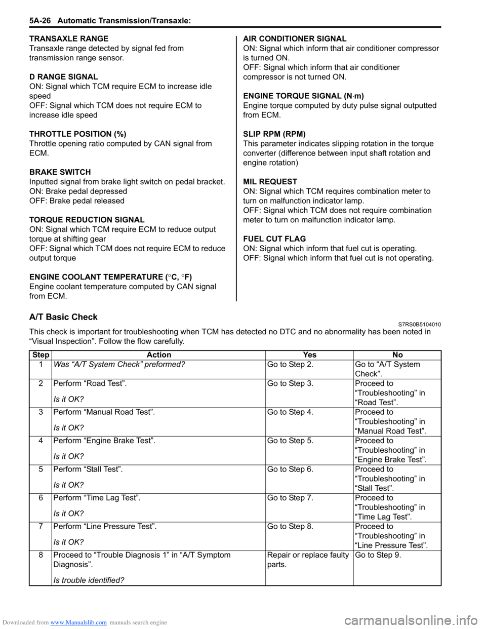
Downloaded from www.Manualslib.com manuals search engine 5A-26 Automatic Transmission/Transaxle:
TRANSAXLE RANGE
Transaxle range detected by signal fed from
transmission range sensor.
D RANGE SIGNAL
ON: Signal which TCM require ECM to increase idle
speed
OFF: Signal which TCM does not require ECM to
increase idle speed
THROTTLE POSITION (%)
Throttle opening ratio computed by CAN signal from
ECM.
BRAKE SWITCH
Inputted signal from brake light switch on pedal bracket.
ON: Brake pedal depressed
OFF: Brake pedal released
TORQUE REDUCTION SIGNAL
ON: Signal which TCM require ECM to reduce output
torque at shifting gear
OFF: Signal which TCM does not require ECM to reduce
output torque
ENGINE COOLANT TEMPERATURE ( ┬░C, ┬░F)
Engine coolant temperature computed by CAN signal
from ECM. AIR CONDITIONER SIGNAL
ON: Signal which inform that air conditioner compressor
is turned ON.
OFF: Signal which inform that air conditioner
compressor is not turned ON.
ENGINE TORQUE SIGNAL (N
тЛЕm)
Engine torque computed by duty pulse signal outputted
from ECM.
SLIP RPM (RPM)
This parameter indicates slip ping rotation in the torque
converter (difference between input shaft rotation and
engine rotation)
MIL REQUEST
ON: Signal which TCM requires combination meter to
turn on malfunction indicator lamp.
OFF: Signal which TCM does not require combination
meter to turn on malf unction indicator lamp.
FUEL CUT FLAG
ON: Signal which inform that fuel cut is operating.
OFF: Signal which inform that fuel cut is not operating.
A/T Basic CheckS7RS0B5104010
This check is important for troubleshooting when TCM has detected no DTC and no abnormality has been noted in
тАЬVisual InspectionтАЭ. Fo llow the flow carefully.
Step Action YesNo
1 Was тАЬA/T System CheckтАЭ preformed? Go to Step 2.Go to тАЬA/T System
CheckтАЭ.
2 Perform тАЬRoad TestтАЭ.
Is it OK? Go to Step 3.
Proceed to
тАЬTroubleshootingтАЭ in
тАЬRoad TestтАЭ.
3 Perform тАЬManual Road TestтАЭ.
Is it OK? Go to Step 4.
Proceed to
тАЬTroubleshootingтАЭ in
тАЬManual Road TestтАЭ.
4 Perform тАЬEngine Brake TestтАЭ.
Is it OK? Go to Step 5.
Proceed to
тАЬTroubleshootingтАЭ in
тАЬEngine Brake TestтАЭ.
5 Perform тАЬStall TestтАЭ.
Is it OK? Go to Step 6.
Proceed to
тАЬTroubleshootingтАЭ in
тАЬStall TestтАЭ.
6 Perform тАЬTime Lag TestтАЭ.
Is it OK? Go to Step 7.
Proceed to
тАЬTroubleshootingтАЭ in
тАЬTime Lag TestтАЭ.
7 Perform тАЬLine Pressure TestтАЭ.
Is it OK? Go to Step 8.
Proceed to
тАЬTroubleshootingтАЭ in
тАЬLine Pressure TestтАЭ.
8 Proceed to тАЬTrouble Diag nosis 1тАЭ in тАЬA/T Symptom
DiagnosisтАЭ.
Is trouble identified? Repair or replace faulty
parts.
Go to Step 9.
Page 934 of 1496

Downloaded from www.Manualslib.com manuals search engine 7-ii Table of Contents
Recommended Service Material ....................... 7B-33
Special Tool ...................................................... 7B-33
Automatic Type .................... .................................7B-34
Precautions.........................................................7B-34 A/C System Caution .......................................... 7B-34
Precautions in Diagnosing Trouble ................... 7B-34
Precautions on Servicing A/C System .............. 7B-34
General Description .......... .................................7B-34
Auto A/C System Descript ion ............................ 7B-34
HVAC Control Module Operation Description ... 7B-36
Refrigerant Type Identifica tion .......................... 7B-36
Sub-Cool A/C System Description .................... 7B-36
A/C Operation Description ................................ 7B-36
On-Board Diagnostic System Description ......... 7B-37
Schematic and Routing Diagram ......................7B-37 Major Components of A/C System .................... 7B-37
A/C System Wiring Diagra m ............................. 7B-38
Diagnostic Information and Procedures ..........7B-39 A/C System Symptom Diagnosis ...................... 7B-39
Abnormal Noise Sympto m Diagnosis of A/C
System ............................................................ 7B-42
DTC Check........................................................ 7B-42
DTC Clearance ................................................. 7B-43
DTC Table ......................................................... 7B-44
Fail-Safe Table ................. ................................. 7B-45
Scan Tool Data ................................................. 7B-46
Air Conditioning System Check......................... 7B-47
Visual Inspection ............................................... 7B-49
DTC B1502: Inside Air Temperature Sensor and/or Its Circuit Malfunction .......................... 7B-49
DTC B1503: A/C Evaporator Air Temperature Sensor and/or Its Circuit Malfunction .............. 7B-50
DTC B1504: Sunload Sensor and/or Its Circuit Malfunction ......... ................................. 7B-52
DTC B1511: Temperature Control Actuator (Position Sensor) and/or Its Circuit
Malfunction ...................................................... 7B-53
DTC B1512: Air flow Control Actuator (Position Sensor) and/or Its Circuit
Malfunction ...................................................... 7B-55
DTC B1513: Temperature Control Actuator and/or Its Circuit Malfunction .......................... 7B-57
DTC B1514: Air Flow Co ntrol Actuator and/or
Its Circuit Malfunction ...................................... 7B-60
DTC B1541: HVAC Control Module Back-Up Power Supply Malfunction .............................. 7B-62
DTC B1546: A/C Refrigerant Pressure Malfunction ...................................................... 7B-63
DTC B1551: Serial Communication Circuit Malfunction ...................................................... 7B-63
DTC B1552: Serial Communication Signal Malfunction ...................................................... 7B-64
DTC B1553: CAN Communication Signal Malfunction ...................................................... 7B-65
DTC B1557: Vehicle Speed Sensor Signal Malfunction ...................................................... 7B-65
DTC B1561: Engine Coolant Temperature Sensor Signal Malfunctio n .............................. 7B-66 DTC B1562: Outside Air Temperature Sensor
Signal Malfunction ........................................... 7B-66
DTC B1563: A/C Refr igerant Pressure
Sensor Signal Malfunction .............................. 7B-66
Inspection of HVAC Control Module and Its Circuit .............................................................. 7B-67
A/C System Performance Inspection ................ 7B-70
A/C System Inspection at ECM ......................... 7B-70
Repair Instructions ............ ................................7B-71
Operation Procedure for Refrigerant Charge .... 7B-71
HVAC Unit Components ................................... 7B-72
HVAC Unit Removal and In stallation ................ 7B-73
Temperature Control Actuator Removal and Installation ....................................................... 7B-73
Temperature Control Actuat or Inspection ......... 7B-73
Air Flow Control Actuator Removal and Installation ....................................................... 7B-74
Air Flow Control Actuator Inspection ................. 7B-74
Air Intake Control Actuator Removal and Installation ....................................................... 7B-75
Air Intake Control Actuator Inspection............... 7B-75
Actuator Linkage Inspection .............................. 7B-76
Blower Motor Controller Removal and Installation ....................................................... 7B-76
Blower Motor Controller Inspection ................... 7B-76
HVAC Control Module Removal and Installation ....................................................... 7B-77
Sunload Sensor Removal and Installation ........ 7B-77
Sunload Sensor Inspection ............................... 7B-77
Outside Air Temperature Sensor Removal and Installation ................................................ 7B-77
Outside Air Temperature Sensor Inspection ..... 7B-77
Inside Air Temperature Sensor Removal and Installation ....................................................... 7B-78
Inside Air Temperature Sens or Inspection ........ 7B-78
Condenser Assembly On-Vehicle Inspection .... 7B-78
Condenser Assembly Removal and Installation ....................................................... 7B-78
Receiver/Dryer Removal and Installation .......... 7B-78
Evaporator Inspection ....................................... 7B-78
Evaporator Temperature Sensor Removal and Installation ................................................ 7B-78
Evaporator Temperature Se nsor Inspection ..... 7B-78
Expansion Valve Removal an d Installation ....... 7B-78
Expansion Valve Inspection .............................. 7B-78
A/C Refrigerant Pressure Sensor and Its Circuit Inspection............................................. 7B-78
A/C Refrigerant Pressu re Sensor Removal
and Installation ................................................ 7B-78
Compressor Relay Inspection .
.......................... 7B-78
Compressor Drive Belt Inspection and Adjustment ...................................................... 7B-78
Compressor Drive Belt Removal and Installation ....................................................... 7B-79
Compressor Assembly Removal and Installation ....................................................... 7B-79
Compressor Assembly Components................. 7B-79
Magnet Clutch Removal and Installation........... 7B-79
Magnet Clutch Inspection.................................. 7B-79
Relief Valve Inspection...................................... 7B-79
Page 949 of 1496
Downloaded from www.Manualslib.com manuals search engine Air Conditioning System: Manual Type 7B-1
HVAC
Air Conditioning System
Manual Type
Precautions
A/C System CautionS7RS0B7210001
CAUTION!
тАв The air conditioning system of this vehicle uses refrigerant HFC-134a (R-134a).
None of refrigerant, compressor oil and component parts is interchangeable between two types of
A/C: one using refrigerant HFC-134a (R-134a) and the other using refrigerant CFC-12 (R-12).
Be sure to check which refrigerant is used be fore any service work including inspection and
maintenance. For identification between these two types, refer to тАЬRefrigerant Type IdentificationтАЭ.
When replenishing or changing refrigerant and comp ressor oil and when replacing parts, make sure
that the material or the part to be used is appropriate to the A/C installed in the vehicle being
serviced.
Use of incorrect one will result in leakage of refrigerant, damage in parts or other faulty condition.
тАв When servicing the compressor, keep dirt or foreign material away from getting on or into the compressor parts and system. Clean tools and a clean work area are important for proper service.
The compressor connection and the outside of the compressor should be cleaned before any тАЬOn
vehicleтАЭ repair or before removal of the compressor. The parts must be kept clean at all times and
any parts to be reassembled should be cleaned with trichloromethane, naphtha, kerosene or
equivalent solvent and dried with dry air. Use only lint free cloths to wipe parts.
тАв When compressor is removed from the vehicle for servicing, the oil remaining in the compressor
should be discarded and new refrigerant oil added to the compressor.
Minor repair procedures may be done on the vehicle without discharging the system. Major repair
procedures require that the system be discharged of refrigerant.
Precautions on Servicing A/C SystemS7RS0B7210002
WARNING!
Should refrigerant HFC-134a (R-134a) is exposed to your eye(s), consult a doctor immediately.
тАв Do not use your hand to rub affected eye(s). Instead, use fresh cold water to splash it over affected area to thus gradually raise its temperature above the freezing point.
тАв Obtain proper treatment as soon as possible from a doctor or eye specialist. Should liquid refrigerant HFC-134a (R-134a) is exposed to your skin, such affected part should be treated in the
same manner as when skin is frostbitten or frozen.
Handling Refrigerant HFC-134a (R-134a)
тАв Always wear goggles to protect your eyes.
тАв Avoid direct contact to liquid refrigerant.
тАв Do not heat refrigerant container higher than 40 ┬░C (104 ┬░ F).
тАв Do not discharge refrigerant into atmosphere.
тАв Do not expose bright metals to liquid refrigerant. Refrig erant combined with moisture is corrosive and tarnishes
surfaces of bright metals including chrome.
Page 950 of 1496
Downloaded from www.Manualslib.com manuals search engine 7B-2 Air Conditioning System: Manual Type
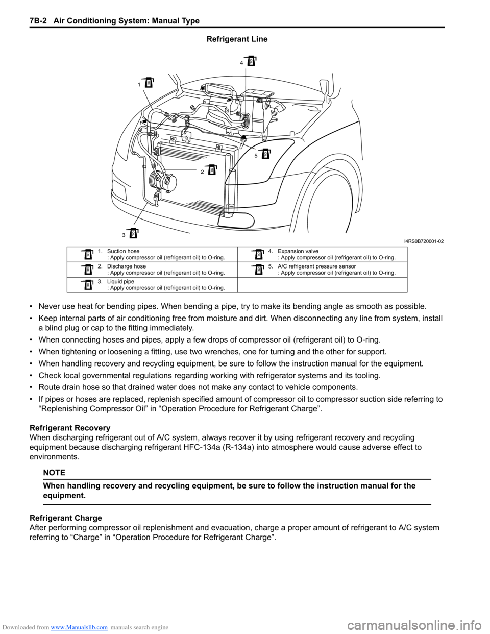
Refrigerant Line
тАв Never use heat for bending pipes. When bending a pipe , try to make its bending angle as smooth as possible.
тАв Keep internal parts of air conditioning free from moistu re and dirt. When disconnecting any line from system, install
a blind plug or cap to the fitting immediately.
тАв When connecting hoses and pipes, apply a few drops of compressor oil (refrigerant oil) to O-ring.
тАв When tightening or loosening a fitting, use two wrenches, one for turning and the other for support.
тАв When handling recovery and recycling equipment, be sure to follow the instruction manual for the equipment.
тАв Check local governmental regulations regarding working with refrigerator systems and its tooling.
тАв Route drain hose so that drained water does not make any contact to vehicle components.
тАв If pipes or hoses are replaced, replenish specified amount of compressor oil to compre ssor suction side referring to
тАЬReplenishing Compressor OilтАЭ in тАЬOperation Procedure for Refrigerant ChargeтАЭ.
Refrigerant Recovery
When discharging refrigerant out of A/C system, always recover it by using refrigerant recovery and recycling
equipment because discharging refrigerant HFC-134a (R-1 34a) into atmosphere would cause adverse effect to
environments.
NOTE
When handling recovery and recycling equipment, be sure to follow the instruction manual for the
equipment.
Refrigerant Charge
After performing compressor oil replenishment and evacuat ion, charge a proper amount of refrigerant to A/C system
referring to тАЬChargeтАЭ in тАЬOperation Procedure for Refrigerant ChargeтАЭ.
3
1
2
4
5
I4RS0B720001-02
1. Suction hose : Apply compressor oil (refrigerant oil) to O-ring. 4. Expansion valve
: Apply compressor oil (refrigerant oil) to O-ring.
2. Discharge hose : Apply compressor oil (refrigerant oil) to O-ring. 5. A/C refrigerant pressure sensor
: Apply compressor oil (refrigerant oil) to O-ring.
3. Liquid pipe : Apply compressor oil (refrigerant oil) to O-ring.
Page 951 of 1496
Downloaded from www.Manualslib.com manuals search engine Air Conditioning System: Manual Type 7B-3
General Description
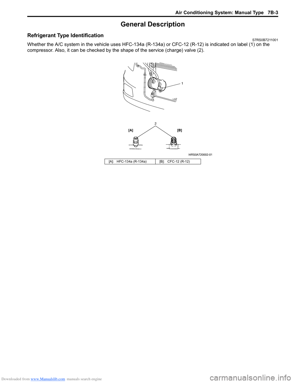
Refrigerant Type IdentificationS7RS0B7211001
Whether the A/C system in the vehicle uses HFC-134a (R-134a) or CFC-12 (R-12) is indicated on label (1) on the
compressor. Also, it can be checked by th e shape of the service (charge) valve (2).
[A]: HFC-134a (R-134a) [B]: CFC-12 (R-12)
I4RS0A720002-01
Page 955 of 1496
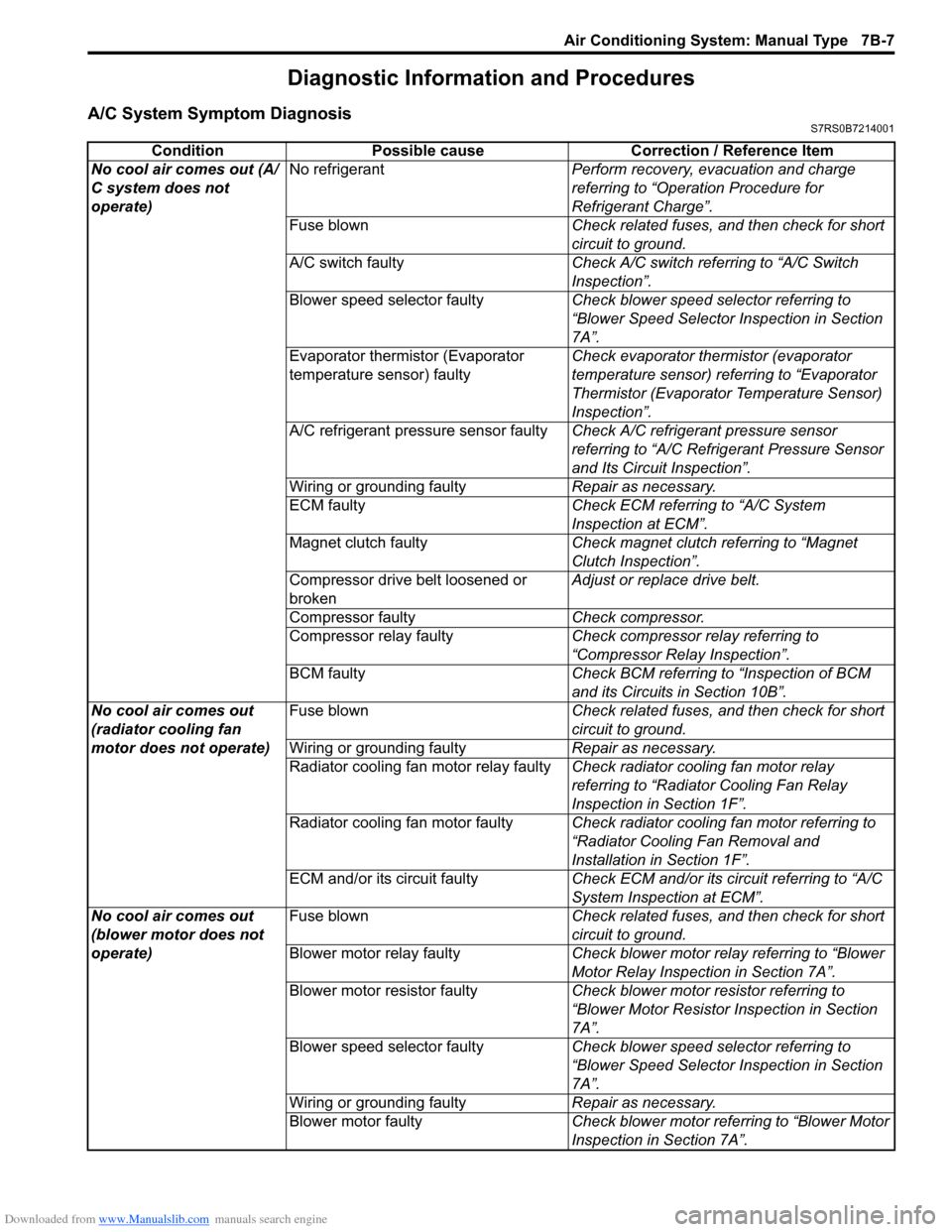
Downloaded from www.Manualslib.com manuals search engine Air Conditioning System: Manual Type 7B-7
Diagnostic Information and Procedures
A/C System Symptom DiagnosisS7RS0B7214001
ConditionPossible cause Correction / Reference Item
No cool air comes out (A/
C system does not
operate) No refrigerant
Perform recovery, evacuation and charge
referring to тАЬOperation Procedure for
Refrigerant ChargeтАЭ.
Fuse blown Check related fuses, and then check for short
circuit to ground.
A/C switch faulty Check A/C switch referring to тАЬA/C Switch
InspectionтАЭ.
Blower speed selector faulty Check blower speed selector referring to
тАЬBlower Speed Selector Inspection in Section
7AтАЭ.
Evaporator thermistor (Evaporator
temperature sensor) faulty Check evaporator thermistor (evaporator
temperature sensor) referring to тАЬEvaporator
Thermistor (Evaporator Temperature Sensor)
InspectionтАЭ.
A/C refrigerant pressure sensor faulty Check A/C refrigerant pressure sensor
referring to тАЬA/C Refrigerant Pressure Sensor
and Its Circuit InspectionтАЭ.
Wiring or grounding faulty Repair as necessary.
ECM faulty Check ECM referring to тАЬA/C System
Inspection at ECMтАЭ.
Magnet clutch faulty Check magnet clutch referring to тАЬMagnet
Clutch InspectionтАЭ.
Compressor drive belt loosened or
broken Adjust or replace drive belt.
Compressor faulty Check compressor.
Compressor relay faulty Check compressor relay referring to
тАЬCompressor Relay InspectionтАЭ.
BCM faulty Check BCM referring to тАЬInspection of BCM
and its Circuits in Section 10BтАЭ.
No cool air comes out
(radiator cooling fan
motor does not operate) Fuse blown
Check related fuses, and then check for short
circuit to ground.
Wiring or grounding faulty Repair as necessary.
Radiator cooling fan motor relay faulty Check radiator cooling fan motor relay
referring to тАЬRadiator Cooling Fan Relay
Inspection in Section 1FтАЭ.
Radiator cooling fan motor faulty Check radiator cooling fan motor referring to
тАЬRadiator Cooling Fan Removal and
Installation in Section 1FтАЭ.
ECM and/or its circuit faulty Check ECM and/or its circuit referring to тАЬA/C
System Inspection at ECMтАЭ.
No cool air comes out
(blower motor does not
operate) Fuse blown
Check related fuses, and then check for short
circuit to ground.
Blower motor relay faulty Check blower motor relay referring to тАЬBlower
Motor Relay Inspection in Section 7AтАЭ.
Blower motor resistor faulty Check blower motor resistor referring to
тАЬBlower Motor Resistor Inspection in Section
7AтАЭ.
Blower speed selector faulty Check blower speed selector referring to
тАЬBlower Speed Selector Inspection in Section
7AтАЭ.
Wiring or grounding faulty Repair as necessary.
Blower motor faulty Check blower motor referring to тАЬBlower Motor
Inspection in Section 7AтАЭ.