elec SUZUKI SWIFT 2005 2.G Service User Guide
[x] Cancel search | Manufacturer: SUZUKI, Model Year: 2005, Model line: SWIFT, Model: SUZUKI SWIFT 2005 2.GPages: 1496, PDF Size: 34.44 MB
Page 16 of 1496
Downloaded from www.Manualslib.com manuals search engine 00-11 Precautions:
Precaution for Vehicle Equipped with ESP®
System
S7RS0B0000015
• When testing with any of the following equipments
(when vehicle is tested by rotating wheels (tires)
under vehicle stop), be sure to deactivate ESP ®
system referring to “Precautions in Speedometer Test
or Other Tests in Section 4F” to obtain correct data.
– 2 or 4-wheel chassis dynamometer
– Speedometer tester
– Brake tester
–Etc.
ESP ® control module
• When ESP ® control module is removed / installed, do
not use impact wrenches which generate shock or
impact to avoid damaging sensors in ESP ® control
module.
• When any of the following operation is done, calibrate steering angle sensor referring to “Sensor Calibration
in Section 4F”.
– When battery or dome fuse is removed.
– When steering angle sensor is replaced.
Brake CautionS7RS0B0000014
CAUTION!
All brake fasteners are important attaching
parts in that they could affect the
performance of vital parts and systems, and/
or could result in major repair expense. They
must be replaced with one of same part
number or with an eq uivalent part if
replacement becomes necessary. Do not use
a replacement part of lesser quality or
substitute design. Torque values must be
used as specified during reassembly to
assure proper retention of all parts. There is
to be no welding as it may result in extensive
damage and weakening of the metal.
Repair Instructions
Electrical Circuit Inspection ProcedureS7RS0B0006001
While there are various electrical circuit inspection
methods, described here is a general method to check
its open and short circuit by using an ohmmeter and a
voltmeter.
Open Circuit Check
Possible causes for the open circuit are as follows. As
the cause is in the connector or terminal in many cases,
they need to be checked particularly carefully.
• Loose connection of connector
• Poor contact of terminal (due to dirt, corrosion or rust
on it, poor contact tension, entry of foreign object etc.)
• Wire harness being open
When checking system circuits including an electronic
control unit such as ECM, TCM, ABS control module,
etc., it is important to perfor m careful check, starting with
items which are easier to check.
1) Disconnect negative (–) cable from battery
2) Check each connector at both ends of the circuit being checked for loose connection. Also check lock
condition of connector if equipped with connector
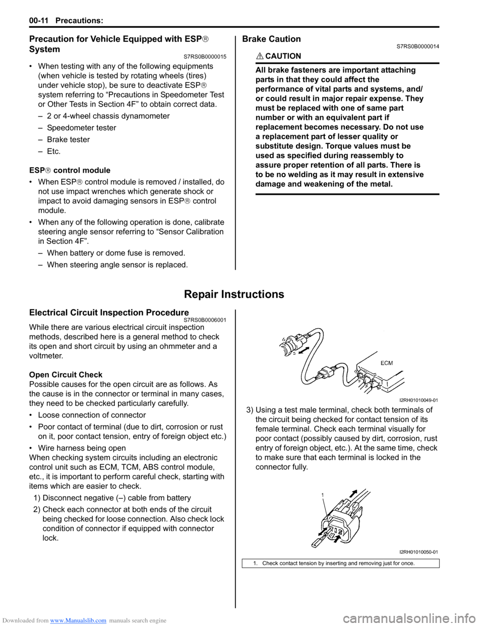
lock. 3) Using a test male terminal
, check both terminals of
the circuit being checked for contact tension of its
female terminal. Check each terminal visually for
poor contact (possibly caused by dirt, corrosion, rust
entry of foreign object, etc.). At the same time, check
to make sure that each te rminal is locked in the
connector fully.
1. Check contact tension by inserting and removing just for once.
I2RH01010049-01
I2RH01010050-01
Page 18 of 1496
Downloaded from www.Manualslib.com manuals search engine 00-13 Precautions:
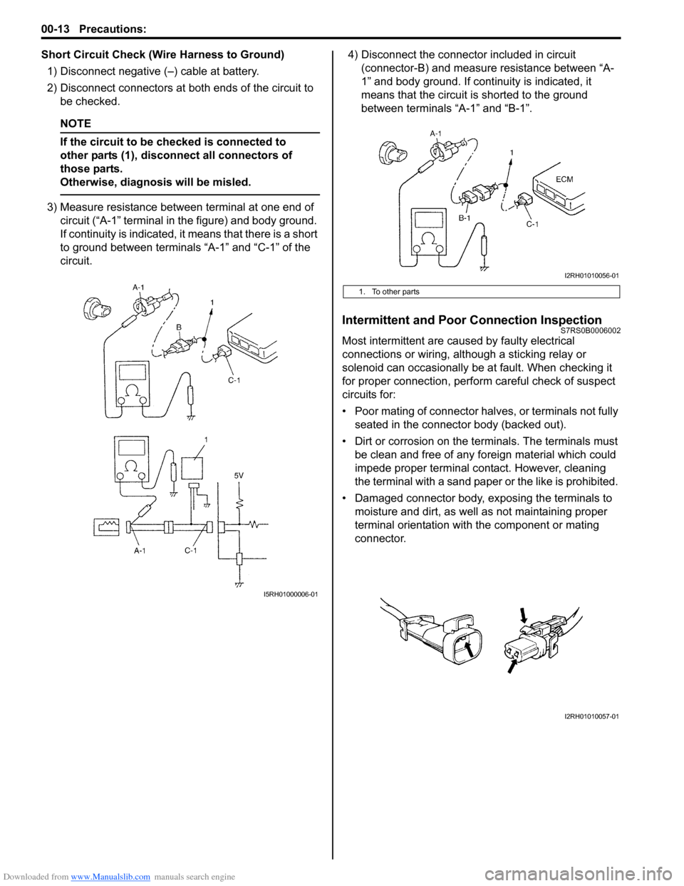
Short Circuit Check (Wire Harness to Ground)1) Disconnect negative (–) cable at battery.
2) Disconnect connectors at bot h ends of the circuit to
be checked.
NOTE
If the circuit to be checked is connected to
other parts (1), disconnect all connectors of
those parts.
Otherwise, diagnosis will be misled.
3) Measure resistance between terminal at one end of circuit (“A-1” terminal in the figure) and body ground.
If continuity is indicated, it means that there is a short
to ground between terminals “A-1” and “C-1” of the
circuit. 4) Disconnect the connector included in circuit
(connector-B) and measure resistance between “A-
1” and body ground. If continuity is indicated, it
means that the circuit is shorted to the ground
between terminals “A-1” and “B-1”.
Intermittent and Poor Connection InspectionS7RS0B0006002
Most intermittent are caused by faulty electrical
connections or wiring, although a sticking relay or
solenoid can occasionally be at fault. When checking it
for proper connection, perfor m careful check of suspect
circuits for:
• Poor mating of connector halves, or terminals not fully seated in the connector body (backed out).
• Dirt or corrosion on the terminals. The terminals must be clean and free of any foreign material which could
impede proper terminal contact. However, cleaning
the terminal with a sand paper or the like is prohibited.
• Damaged connector body, exposing the terminals to moisture and dirt, as well as not maintaining proper
terminal orientation with the component or mating
connector.
I5RH01000006-01
1. To other parts
I2RH01010056-01
I2RH01010057-01
Page 22 of 1496
Downloaded from www.Manualslib.com manuals search engine 0A-1 General Information:
General Information
General Information
General Description
AbbreviationsS7RS0B0101001
A:
ABDC: After Bottom Dead Center
ABS: Anti-lock Brake System
AC: Alternating Current
A/C: Air Conditioning
A-ELR: Automatic-Emergency Locking Retractor
A/F: Air Fuel Mixture Ratio
ALR: Automatic Locking Retractor
API: American Petroleum Institute
APP sensor: Accelerator Pedal Position Sensor
A/T: Automatic Transmission , Automatic Transaxle
AT D C : After Top Dead Center
ATF: Automatic Transmission Fluid, Automatic
Transaxle Fluid
B:
B+: Battery Positive Voltage
BBDC: Before Bottom Dead Center
BCM: Body Electrical Control Module
BDC: Bottom Dead Center
BTDC: Before Top Dead Center
C:
CAN: Controller Area Network
CKT: Circuit
CKP Sensor: Crankshaft Position Sensor
CMP Sensor: Camshaft Position Sensor
CO: Carbon Monoxide
CPP Switch: Clutch Pedal Position Switch (Clutch
Switch, Clutch Start Switch)
CPU: Central Processing Unit
CRS: Child Restraint System
D:
DC: Direct Current
DLC: Data Link Connector (Assembly Line Diag. Link,
ALDL, Serial Data Link, SDL)
DOHC: Double Over Head Camshaft
DOJ: Double Offset Joint
DRL: Daytime Running Light
DTC: Diagnostic Trouble Code (Diagnostic Code)
E:
EBCM: Electronic Brake Cont rol Module, ABS Control
Module
EBD: Electronic Brake Force Distribution
ECM: Engine Control Module
ECT Sensor: Engine Coolant Temperature Sensor (Water Temp. Sensor, WTS)
EFE Heater: Early Fuel Evaporation Heater (Positive
Temperature Coefficient, PTC Heater)
EGR: Exhaust Gas Recirculation
EGRT Sensor: EGR Temperature Sensor (Recirculated
Exhaust Gas Temp. Sensor, REGTS)
ELR: Emergency Locking Retractor
ESP ®: Electronic Stability Program
EPS: Electronic Power Steering
EVAP: Evaporative Emission EVAP Canister:
Evaporative Emission Canister
(Charcoal Canister)
F:
4WD: 4 Wheel
Drive
G:
GEN: Generator
GND: Ground
GPS: Global Positioning System
H:
HVAC: Heating, Ventilating and Air Conditioning
HC: Hydrocarbons
HO2S: Heated Oxygen Sensor
I:
IAC Valve: Idle Air Control Valve (Idle Speed Control
Solenoid Valve, ISC Solenoid Valve)
IAT Sensor: Intake Air Temperature Sensor (Air
temperature Sensor, ATS)
ICM: Immobilizer Control Module
IG: Ignition
ISC Actuator: Idle Speed Control Actuator
L:
LH: Left Hand
LHD: Left Hand Drive Vehicle
LSPV: Load Sensing Proportioning Valve
M:
MAF Sensor: Mass Air Flow Sensor (Air Flow Sensor, AFS, Air Flow Meter, AFM)
MAP Sensor: Manifold Absolute Pressure Sensor
(Pressure Sensor, PS)
Max: Maximum
MFI: Multiport Fuel Injection (Mu ltipoint Fuel Injection)
Min: Minimum
MIL: Malfunction Indicator Lamp (“SERVICE ENGINE
SOON” Light)
M/T: Manual Transmission, Manual Transaxle
N:
NOx: Nitrogen Oxides
O:
OBD: On-Board Diagnostic System (Self-Diagnosis
Function)
O/D: Overdrive
OHC: Over Head Camshaft
O2S: Oxygen Sensor
P:
PCM: Powertrain Control Module
PCV: Positive Crankcase Ventilation
PNP: Park / Neutral Position
P/S: Power Steering
PSP Switch: Power Steering Pressure Switch (P/S
Pressure Switch)
R:
RH: Right Hand
RHD: Right Hand Drive Vehicle
S:
SAE: Society of Automotive Engineers
Page 24 of 1496
Downloaded from www.Manualslib.com manuals search engine 0A-3 General Information:
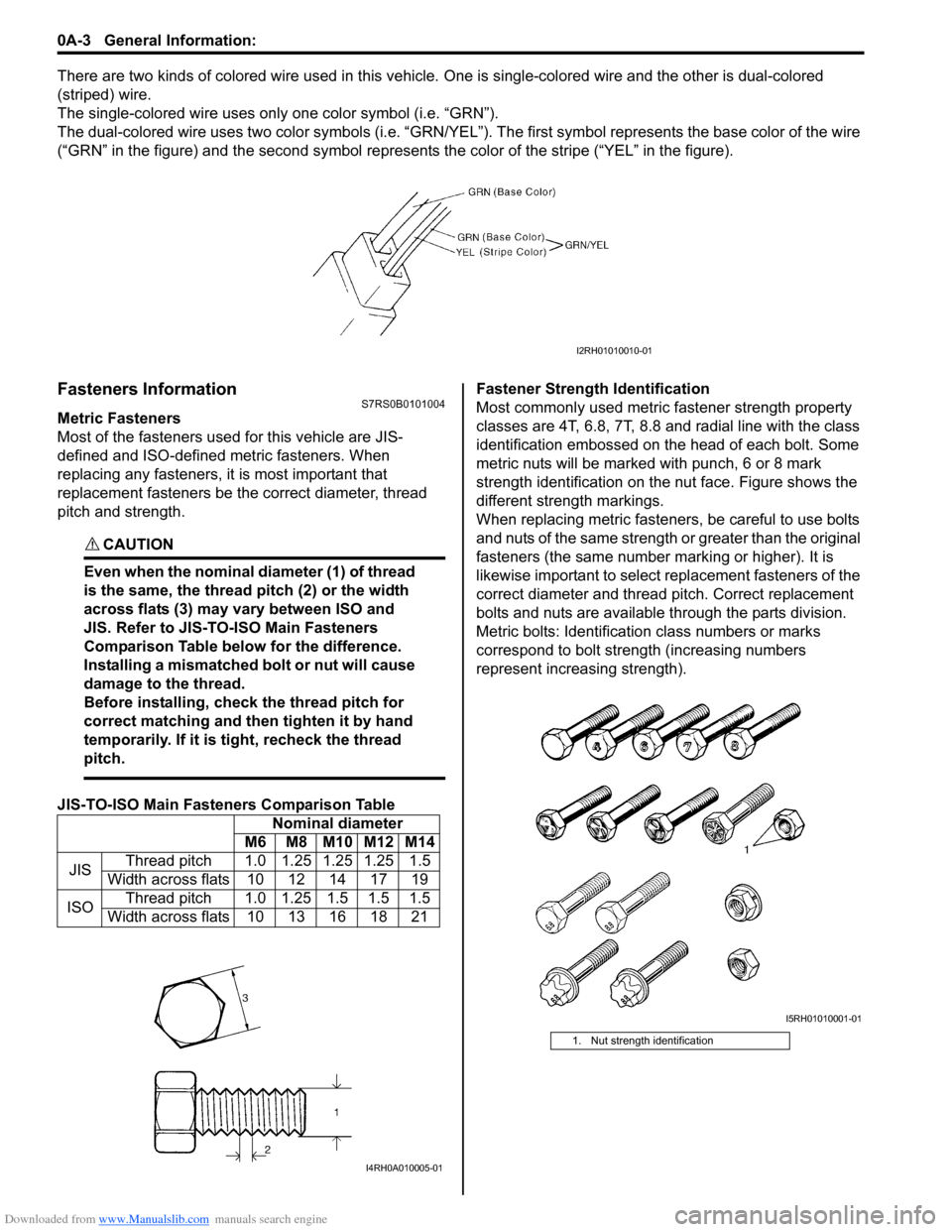
There are two kinds of colored wire used in this vehicle. One is single-colored wire and the other is dual-colored
(striped) wire.
The single-colored wire uses only one color symbol (i.e. “GRN”).
The dual-colored wire uses two color sy mbols (i.e. “GRN/YEL”). The first symbo l represents the base color of the wire
(“GRN” in the figure) and the second symbol represents the color of the stripe (“YEL” in the figure).
Fasteners InformationS7RS0B0101004
Metric Fasteners
Most of the fasteners used for this vehicle are JIS-
defined and ISO-defined metric fasteners. When
replacing any fasteners, it is most important that
replacement fasteners be the correct diameter, thread
pitch and strength.
CAUTION!
Even when the nominal diameter (1) of thread
is the same, the thread pitch (2) or the width
across flats (3) may vary between ISO and
JIS. Refer to JIS-TO-ISO Main Fasteners
Comparison Table below for the difference.
Installing a mismatched bolt or nut will cause
damage to the thread.
Before installing, check the thread pitch for
correct matching and then tighten it by hand
temporarily. If it is tight, recheck the thread
pitch.
JIS-TO-ISO Main Fasteners Comparison Table Fastener Strength Identification
Most commonly used metric fastener strength property
classes are 4T, 6.8, 7T, 8.8 and radial line with the class
identification embossed on the head of each bolt. Some
metric nuts will be marked with punch, 6 or 8 mark
strength identification on the nut face. Figure shows the
different strength markings.
When replacing metric fasteners, be careful to use bolts
and nuts of the same strength or greater than the original
fasteners (the same number marking or higher). It is
likewise important to select replacement fasteners of the
correct diameter and thread
pitch. Correct replacement
bolts and nuts are available through the parts division.
Metric bolts: Identification class numbers or marks
correspond to bolt strength (increasing numbers
represent increasing strength).
I2RH01010010-01
Nominal diameter
M6 M8 M10 M12 M14
JIS Thread pitch 1.0 1.25 1.25 1.25 1.5
Width across flats 10 12 14 17 19
ISO Thread pitch 1.0 1.25 1.5 1.5 1.5
Width across flats 10 13 16 18 21
I4RH0A010005-01
1. Nut strength identification
I5RH01010001-01
Page 35 of 1496
Downloaded from www.Manualslib.com manuals search engine Maintenance and Lubrication: 0B-5
4) Screw new filter on oil filter stand by hand until the filter O-ring contacts mounting surface.
CAUTION!
To tighten oil filter prop erly, it is important to
accurately identify the position at which filter
O-ring first contacts mounting surface.
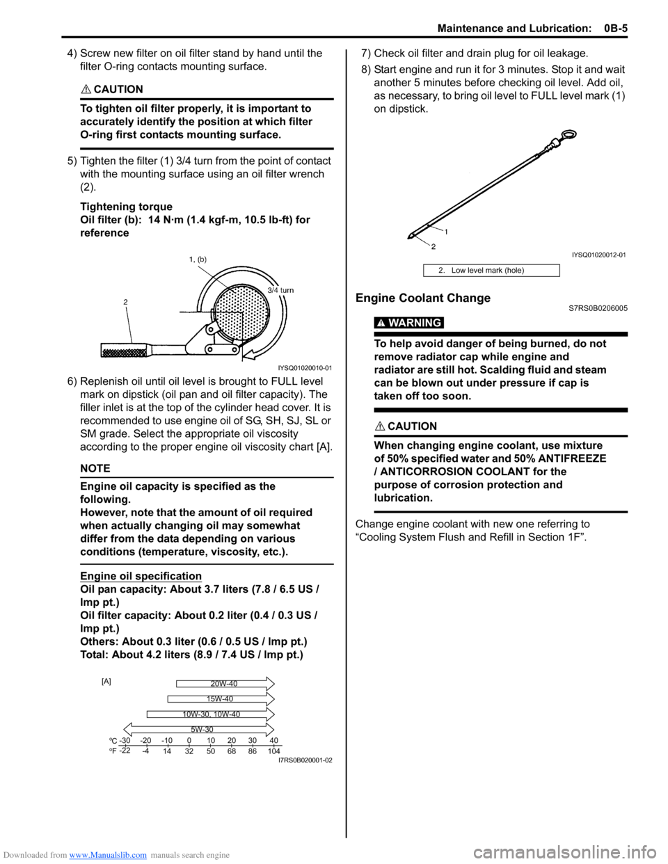
5) Tighten the filter (1) 3/4 tu rn from the point of contact
with the mounting surface using an oil filter wrench
(2).
Tightening torque
Oil filter (b): 14 N·m (1 .4 kgf-m, 10.5 lb-ft) for
reference
6) Replenish oil until oil leve l is brought to FULL level
mark on dipstick (oil pan and oil filter capacity). The
filler inlet is at the top of the cylinder head cover. It is
recommended to use engine oil of SG, SH, SJ, SL or
SM grade. Select the appropriate oil viscosity
according to the proper engine oil viscosity chart [A].
NOTE
Engine oil capacity is specified as the
following.
However, note that the amount of oil required
when actually changing oil may somewhat
differ from the data depending on various
conditions (temperature, viscosity, etc.).
Engine oil specification
Oil pan capacity: About 3.7 liters (7.8 / 6.5 US /
lmp pt.)
Oil filter capacity: About 0.2 liter (0.4 / 0.3 US /
lmp pt.)
Others: About 0.3 liter (0 .6 / 0.5 US / lmp pt.)
Total: About 4.2 liters (8.9 / 7.4 US / lmp pt.) 7) Check oil filter and drain plug for oil leakage.
8) Start engine and run it for 3 minutes. Stop it and wait
another 5 minutes before checking oil level. Add oil,
as necessary, to bring oil le vel to FULL level mark (1)
on dipstick.
Engine Coolant ChangeS7RS0B0206005
WARNING!
To help avoid danger of being burned, do not
remove radiator cap while engine and
radiator are still hot. Scalding fluid and steam
can be blown out under pressure if cap is
taken off too soon.
CAUTION!
When changing engine coolant, use mixture
of 50% specified water and 50% ANTIFREEZE
/ ANTICORROSION COOLANT for the
purpose of corrosion protection and
lubrication.
Change engine coolant with new one referring to
“Cooling System Flush and Refill in Section 1F”.
IYSQ01020010-01
Co
Fo-30
-22 -20
-4 -10
14 32 50 68 86 104 010203040
5W-30
20W-40
15W-40
10W-30, 10W-40
[A]
I7RS0B020001-02
2. Low level mark (hole)
IYSQ01020012-01
Page 42 of 1496
Downloaded from www.Manualslib.com manuals search engine 0B-12 Maintenance and Lubrication:
HVAC Air Filter (If Equipped) InspectionS7RS0B0206032
1) Remove HVAC air filter from HVAC unit referring to
“HVAC Air Filter Removal and Installation (If
Equipped) in Section 7A”.
2) Check for dirt and dust. If HVAC air filter is excessively dirty, replace HVAC air filter with new
one. If not, go to next step.
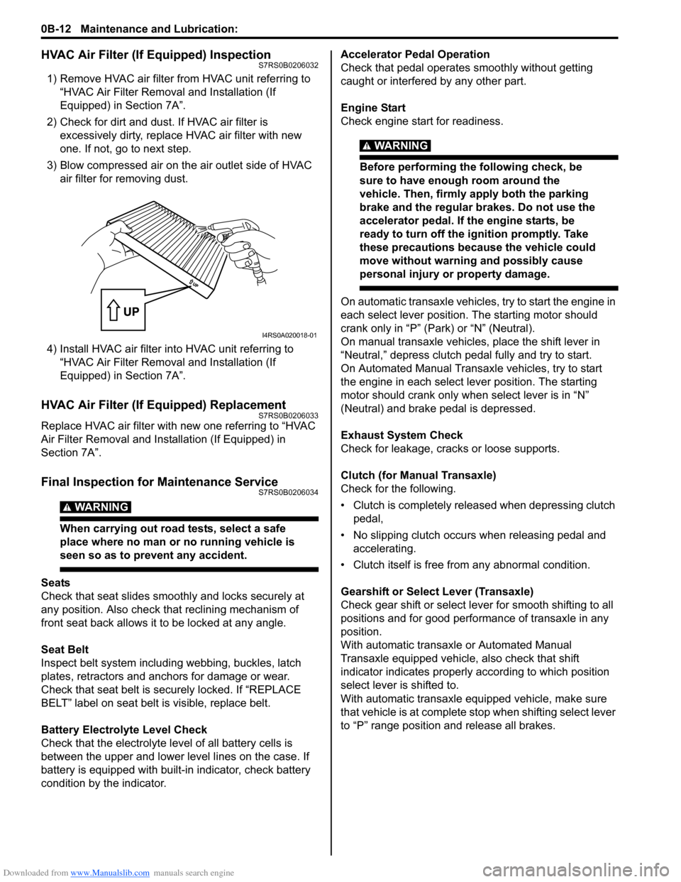
3) Blow compressed air on the air outlet side of HVAC air filter for removing dust.
4) Install HVAC air filter in to HVAC unit referring to
“HVAC Air Filter Removal and Installation (If
Equipped) in Section 7A”.
HVAC Air Filter (If Equipped) ReplacementS7RS0B0206033
Replace HVAC air filter with new one referring to “HVAC
Air Filter Removal and Installation (If Equipped) in
Section 7A”.
Final Inspection for Maintenance ServiceS7RS0B0206034
WARNING!
When carrying out road tests, select a safe
place where no man or no running vehicle is
seen so as to prevent any accident.
Seats
Check that seat slides smoot hly and locks securely at
any position. Also check that reclining mechanism of
front seat back allows it to be locked at any angle.
Seat Belt
Inspect belt system including webbing, buckles, latch
plates, retractors and anchors for damage or wear.
Check that seat belt is securely locked. If “REPLACE
BELT” label on seat belt is visible, replace belt.
Battery Electrolyte Level Check
Check that the electrolyte le vel of all battery cells is
between the upper and lower level lines on the case. If
battery is equipped with built-in indicator, check battery
condition by the indicator. Accelerator Pedal Operation
Check that pedal operates
smoothly without getting
caught or interfered by any other part.
Engine Start
Check engine start for readiness.
WARNING!
Before performing th e following check, be
sure to have enough room around the
vehicle. Then, firmly apply both the parking
brake and the regular brakes. Do not use the
accelerator pedal. If the engine starts, be
ready to turn off the ignition promptly. Take
these precautions because the vehicle could
move without warning and possibly cause
personal injury or property damage.
On automatic transaxle vehicles, try to start the engine in
each select lever position. The starting motor should
crank only in “P” (Park) or “N” (Neutral).
On manual transaxle vehicles, place the shift lever in
“Neutral,” depress clutch pedal fully and try to start.
On Automated Manual Transaxl e vehicles, try to start
the engine in each select le ver position. The starting
motor should crank only when select lever is in “N”
(Neutral) and brake pedal is depressed.
Exhaust System Check
Check for leakage, cracks or loose supports.
Clutch (for Manual Transaxle)
Check for the following.
• Clutch is completely released when depressing clutch pedal,
• No slipping clutch occurs when releasing pedal and accelerating.
• Clutch itself is free fr om any abnormal condition.
Gearshift or Select Lever (Transaxle)
Check gear shift or select lever for smooth shifting to all
positions and for good performance of transaxle in any
position.
With automatic transaxle or Automated Manual
Transaxle equipped vehicle, also check that shift
indicator indicates properly according to which position
select lever is shifted to.
With automatic transaxle equipped vehicle, make sure
that vehicle is at complete stop when shifting select lever
to “P” range position and release all brakes.
I4RS0A020018-01
Page 45 of 1496
Downloaded from www.Manualslib.com manuals search engine Table of Contents 1- i
1
Section 1
CONTENTS
Engine
Precautions ................................................. 1-1
Precautions............................................................. 1-1
Precautions for Engine .......................................... 1-1
Engine General Information and
Diagnosis ............. .................................... 1A-1
Precautions........................................................... 1A-1
Precautions on Engine Service ........................... 1A-1
Precaution on On-Board Diagnostic (OBD) System .............................................................. 1A-1
Precautions in Diagnosing Trouble ..................... 1A-1
Precautions of ECM Circuit Inspection................ 1A-2
Precautions of Electric Throttle Body System
Calibration ......................................................... 1A-2
General Description ............................................. 1A-2 Statement on Cleanliness and Care ................... 1A-2
Engine Diagnosis General Description ............... 1A-3
On-Board Diagnostic System Description ........... 1A-3
Data Link Connector (DLC) ................................. 1A-6
Engine and Emission Control System Description ........................................................ 1A-6
CAN Communication System Description........... 1A-7
Air Intake System Description ............................. 1A-9
Description of Electric Throttle Body System ...... 1A-9
Description of Electric Throttle Body System Calibration ....................................................... 1A-10
Fuel Cut Control Description ............................. 1A-10
Generator Control System Description ............. 1A-11
Electronic Control System Description .............. 1A-12
Engine and Emission Control Input / Output Table ............................................................... 1A-18
Schematic and Routing Diagram ...................... 1A-19 Engine and Emission Control System Diagram .......................................................... 1A-19
Component Locatio n ......................................... 1A-21
Electronic Control System Components Location .......................................................... 1A-21
Diagnostic Information and Procedures .......... 1A-22 Engine and Emission Control System Check.... 1A-22
Malfunction Indicator Lamp (MIL) Check .......... 1A-25
DTC Check ....................................................... 1A-26
DTC Clearance ................................................. 1A-27
DTC Table ......................................................... 1A-27
Fail-Safe Table ................ .................................. 1A-31 Scan Tool Data ................................................. 1A-33
Visual Inspection ............................................... 1A-37
Engine Basic Inspection .................................... 1A-38
Engine Symptom Diagnosis .............................. 1A-41
MIL Does Not Come ON with Ignition Switch
ON and Engine Stop (but Engine Can Be
Started) ........................................................... 1A-47
Malfunction Indicator Lamp Remains ON after Engine Starts................................................... 1A-48
DTC P0010: “A” Camshaft Position Actuator Circuit .............................................................. 1A-49
DTC P0011 / P0012: “A” Camshaft Position - Timing Over-Advanced or System
Performance / -Retarded................................. 1A-52
DTC P0031 / P0032: HO2S Heater Control Circuit Low / High (Sensor-1) .......................... 1A-54
DTC P0037 / P0038: HO2S Heater Control Circuit Low / High (Sensor-2) .......................... 1A-56
DTC P0101: Mass or Volume Air Flow Circuit Range / Performance ...................................... 1A-58
DTC P0102: Mass or Volume Air Flow Circuit Low Input......................................................... 1A-61
DTC P0103: Mass or Volume Air Flow Circuit High Input ........................................................ 1A-63
DTC P0106: Manifold Absolute Pressure /
Barometric Pressure Circuit Range /
Performance.................................................... 1A-64
DTC P0107: Manifold Absolute Pressure /
Barometric Pressure Circ uit Low Input............ 1A-66
DTC P0108: Manifold Absolute Pressure /
Barometric Pressure Circ uit High Input ........... 1A-67
DTC P0111: Intake Air Temperature Sensor 1 Circuit Range / Performance ........................... 1A-69
DTC P0112: Intake Air Temperature Sensor 1 Circuit Low ...................................................... 1A-72
DTC P0113: Intake Air Temperature 1 Sensor Circuit High...................................................... 1A-74
DTC P0116: Engine Coolant Temperature Circuit Range / Performance ........................... 1A-76
DTC P0117: Engine Coolant Temperature Circuit Low ...................................................... 1A-79
DTC P0118: Engine Coolant Temperature Circuit High...................................................... 1A-81
DTC P0122: Throttle / Pedal Position Sensor / Switch “A” (Main) Circuit Low ........................ 1A-83
Page 46 of 1496
Downloaded from www.Manualslib.com manuals search engine 1-ii Table of Contents
DTC P0123: Throttle / Pedal Position Sensor / Switch “A” (Main) Circuit High ....................... 1A-85
DTC P0131 / P0132: O2 Sensor (HO2S) Circuit Low Voltage / High Voltage (Sensor-
1) ..................................................................... 1A-88
DTC P0133: O2 Sensor (HO2S) Circuit Slow
Response (Sensor- 1) ...................................... 1A-91
DTC P0134: O2 Sensor (HO2S) Circuit No Activity Detected (Sensor -1) ........................... 1A-92
DTC P0137 / P0138: O2 Sensor (HO2S) Circuit Low Voltage / High Voltage (Sensor-
2) ..................................................................... 1A-94
DTC P0140: O2 Sensor (HO2S) Circuit No Activity Detected (Sensor -2) ........................... 1A-97
DTC P0171 / P0172: Fuel System Too Lean / Rich ................................................................. 1A-98
DTC P0222: Throttle / Pedal Position Sensor / Switch “B” (Sub) Circuit Low ....................... 1A-100
DTC P0223: Throttle / Pedal Position Sensor / Switch “B” (Sub) Circuit High ...................... 1A-102
DTC P0300 / P0301 / P0302 / P0303 / P0304: Random / Multiple Cylin der Misfire Detected
/ Cylinder 1 / Cylinder 2 / Cylinder 3 /
Cylinder 4 Misfire Detected ........................... 1A-105
DTC P0327 / P0328: Knoc k Sensor 1 Circuit
Low / High ..................................................... 1A-107
DTC P0335: Crankshaft Position (CKP) Sensor “A” Circuit .......................................... 1A-109
DTC P0340: Camshaft Position (CMP) Sensor “A” Circuit .......................................... 1A-111
DTC P0350: Ignition Coil Primary / Secondary Circuit ............................................................ 1A-114
DTC P0401 / P0402: Exhaust Gas Recirculation Flow Insufficient Detected /
Excessive Detected ...................................... 1A-116
DTC P0403: Exhaust Gas Recirculation Control Circuit ................... ............................ 1A-118
DTC P0420: Catalyst System Efficiency
below Threshold ................ ............................ 1A-120
DTC P0443: Evaporativ e Emission System
Purge Control Valve Circuit ........................... 1A-122
DTC P0480: Fan 1 (Radiator Cooling Fan) Control Circuit ................... ............................ 1A-124
DTC P0500: Vehicle Speed Sensor “A” Malfunction .................................................... 1A-128
DTC P0532: A/C Refrigerant Pressure Sensor “A” Circuit Low ... ............................... 1A-130
DTC P0533: A/C Refrigerant Pressure Sensor “A” Circuit High ................................. 1A-132
DTC P0601 / P0602 / P0607: Internal Control Module Memory Check Sum Error / Control
Module Programming Error / Control Module
Performance ................................................. 1A-134
DTC P0616: Starter Relay Circuit Low............ 1A-135
DTC P0617: Starter Relay Circuit High ........... 1A-136
DTC P0620: Generator Control Circuit ........... 1A-137
DTC P0625 / P0626: Generator Field Terminal Circuit Low / High . .......................... 1A-139
DTC P1501 / P1502: Electric Load Current Sensor Circuit Low / High . ............................ 1A-141 DTC P1510: ECM Back-Up Power Supply
Malfunction .................................................... 1A-143
DTC P1603: TCM Trouble Code Detected ..... 1A-144
DTC P1674: CAN Communication (Bus Off Error) ............................................................. 1A-145
DTC P1676: CAN Communication (Reception Error for TCM) ............................................... 1A-148
DTC P1678: CAN Communication (Reception Error for BCM) ............................................... 1A-149
DTC P1685: CAN Communication (Reception Error for ABS/ESP ® Control Module) ........... 1A-150
DTC P2101: Throttle Actuator Control Motor Circuit Range / Performance ......................... 1A-152
DTC P2102: Throttle Actuator Control Motor Circuit Low .................................................... 1A-154
DTC P2103: Throttle Actuator Control Motor Circuit High.................................................... 1A-155
DTC P2111 / P2112: Throttle Actuator Control System - Stuck Open / Closed ...................... 1A-156
DTC P2119: Throttle Actu ator Control Throttle
Body Range / Performance ........................... 1A-157
DTC P2122: Throttle / Pedal Position Sensor / Switch “D” (Main) Circuit Low Input............. 1A-159
DTC P2123: Throttle / Pedal Position Sensor / Switch “D” (Main) Circuit High Input ............ 1A-161
DTC P2127: Throttle Pedal Position Sensor / Switch “E” (Sub) Circuit Low Input ................ 1A-164
DTC P2128: Throttle / Pedal Position Sensor
/ Switc
h “E” (Sub) Circuit High Input ............. 1A-166
DTC P2135: Throttle / Pedal Position Sensor / Switch “A”/“B” (Main / Sub) Voltage
Correlation..................................................... 1A-168
DTC P2138: Throttle / Pedal Position Sensor / Switch “D”/“E” (Main / Sub) Voltage
Correlation..................................................... 1A-171
DTC P2227 / P2228 / P2229: Barometric Pressure Circuit Malfunction ......................... 1A-173
Inspection of ECM and Its Circuits .................. 1A-175
ECM Power and Ground Circuit Check........... 1A-194
Fuel Injector Circuit Check .............................. 1A-198
Fuel Pump and Its Circuit Check..................... 1A-200
Fuel Pressure Check....................................... 1A-203
A/C System Circuits Check ............................. 1A-205
Electric Load Signal Circuit Check .................. 1A-209
Radiator Cooling Fan Low Speed Control System Check ............................................... 1A-211
Radiator Cooling Fan High Speed Control System Check ............................................... 1A-213
Repair Instructions ......... .................................1A-216
Idle Speed and IAC Throttle Valve Opening Inspection ...................................................... 1A-216
Special Tools and Equipmen t .........................1A-217
Special Tool .................................................... 1A-217
Aux. Emission Control Devices ............. 1B-1
Diagnostic Information and Procedures ............1B-1
EGR System Inspection ...................................... 1B-1
Repair Instructions ............ ..................................1B-1
EVAP Canister Purge Inspec tion ........................ 1B-1
Page 47 of 1496
Downloaded from www.Manualslib.com manuals search engine Table of Contents 1-iii
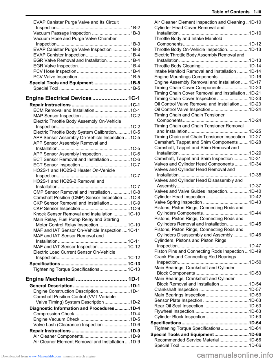
EVAP Canister Purge Valve and Its Circuit
Inspection.......................................................... 1B-2
Vacuum Passage Inspection .............................. 1B-3
Vacuum Hose and Purge Valve Chamber Inspection.......................................................... 1B-3
EVAP Canister Purge Valve Inspection .............. 1B-3
EVAP Canister Inspection ... ................................ 1B-4
EGR Valve Removal and Installation .................. 1B-4
EGR Valve Inspection ......................................... 1B-4
PCV Hose Inspection .......................................... 1B-4
PCV Valve Inspection ......................................... 1B-5
Special Tools and Equipmen t ............................. 1B-5
Special Tool ........................................................ 1B-5
Engine Electrical Devices .. ..................... 1C-1
Repair Instructions .............................................. 1C-1
ECM Removal and Installation ............................ 1C-1
MAP Sensor Inspection ...................................... 1C-2
Electric Throttle Body Assembly On-Vehicle
Inspection.......................................................... 1C-2
Electric Throttle Body System Calibration ........... 1C-5
APP Sensor Assembly On-V ehicle Inspection .... 1C-5
APP Sensor Assembly Removal and Installation ......................................................... 1C-5
APP Sensor Assembly Inspection ...................... 1C-6
ECT Sensor Removal and In stallation ................ 1C-6
ECT Sensor Inspection ....................................... 1C-7
HO2S-1 and HO2S-2 Heater On-Vehicle Inspection.......................................................... 1C-7
HO2S-1 and HO2S-2 Removal and Installation ......................................................... 1C-7
CMP Sensor Removal and In stallation ............... 1C-8
Camshaft Position (CMP) Se nsor Inspection ...... 1C-8
CKP Sensor Removal and Installation ................ 1C-9
CKP Sensor Inspection ....................................... 1C-9
Knock Sensor Removal and Installation ........... 1C-10
Main Relay, Fuel Pump Relay and Starting
Motor Control Relay Inspection....................... 1C-10
MAF and IAT Sensor On-Vehicle Inspection .... 1C-11
MAF and IAT Sensor Removal and Installation ....................................................... 1C-11
MAF and IAT Sensor Inspection ....................... 1C-12
Electric Load Current Sensor On-Vehicle Inspection........................................................ 1C-12
Specifications ..................................................... 1C-13
Tightening Torque Specifications ...................... 1C-13
Engine Mechanical ......... ......................... 1D-1
General Description ............................................. 1D-1
Engine Construction Description ......................... 1D-1
Camshaft Position Control (VVT Variable Valve Timing) System Description .................... 1D-2
Diagnostic Information and Procedures ............ 1D-4 Compression Check ............................................ 1D-4
Engine Vacuum Check ....................................... 1D-5
Valve Lash (Clearance) Inspection ..................... 1D-6
Repair Instructions .............................................. 1D-9 Air Cleaner Components ..................................... 1D-9
Air Cleaner Element Removal and Installation .... 1D-9 Air Cleaner Element Ins
pection and Cleaning ..1D-10
Cylinder Head Co ver Removal and
Installation .......................................................1D-10
Throttle Body and Intake Manifold
Components ....................................................1D-12
Throttle Body On-Vehicle Inspection.................1D-13
Electric Throttle Body Assembly Removal and Installation .......................................................1D-13
Throttle Body Cleaning......................................1D-14
Intake Manifold Removal and Installation .........1D-14
Engine Mountings Components ........................1D-16
Engine Assembly Removal and Installation ......1D-17
Timing Chain Cover Components .....................1D-20
Timing Chain Cover Removal and Installation ..1D-21
Timing Chain Cover Inspection .........................1D-23
Oil Control Valve Removal and Installation .......1D-23
Oil Control Valve Inspection ..............................1D-24
Timing Chain and Chain Tensioner Components ....................................................1D-24
Timing Chain and Chain Tensioner Removal and Installation ................................................1D-25
Timing Chain and Chain Tensioner Inspection ..1D-27
Camshaft, Tappet and Shim Components ........1D-28
Camshaft, Tappet and Shim Removal and Installation .......................................................1D-29
Camshaft, Tappet and Shim Inspection ............1D-31
Valves and Cylinder Head Components ...........1D-34
Valves and Cylinder Head Removal and
Installation .......................................................1D-35
Valves and Cylinder Head Disassembly and Assembly.........................................................1D-37
Valves and Valve Guides Inspection.................1D-40
Cylinder Head Inspection . .................................1D-42
Valve Spring Inspection ....................................1D-43
Pistons, Piston Rings , Connecting Rods and
Cylinders Components ....................................1D-44
Pistons, Piston Rings , Connecting Rods and
Cylinders Removal and Installation .................1D-45
Pistons, Piston Rings , Connecting Rods and
Cylinders Disassembly and Assembly ............1D-46
Cylinders, Pistons and Piston Rings Inspection ........................................................1D-47
Piston Pins and Connecting Rods Inspection ...1D-49
Crank Pin and Connecting Rod Bearings Inspection ........................................................1D-50
Main Bearings, Cran kshaft and Cylinder
Block Components ..........................................1D-53
Main Bearings, Cran kshaft and Cylinder
Block Removal and Installa tion .......................1D-54
Crankshaft Inspection .......................................1D-57
Main Bearings Inspection . .................................1D-59
Sensor Plate Inspection ....................................1D-63
Rear Oil Seal Inspection ...................................1D-63
Flywheel Inspection...........................................1D-63
Cylinder Block Inspection ..................................1D-63
Specifications .................... .................................1D-64
Tightening Torque Specifications ......................1D-64
Special Tools and Equipmen t ...........................1D-66
Recommended Service Material .......................1D-66
Special Tool ......................................................1D-66
Page 50 of 1496
Downloaded from www.Manualslib.com manuals search engine 1-1 Precautions:
Engine
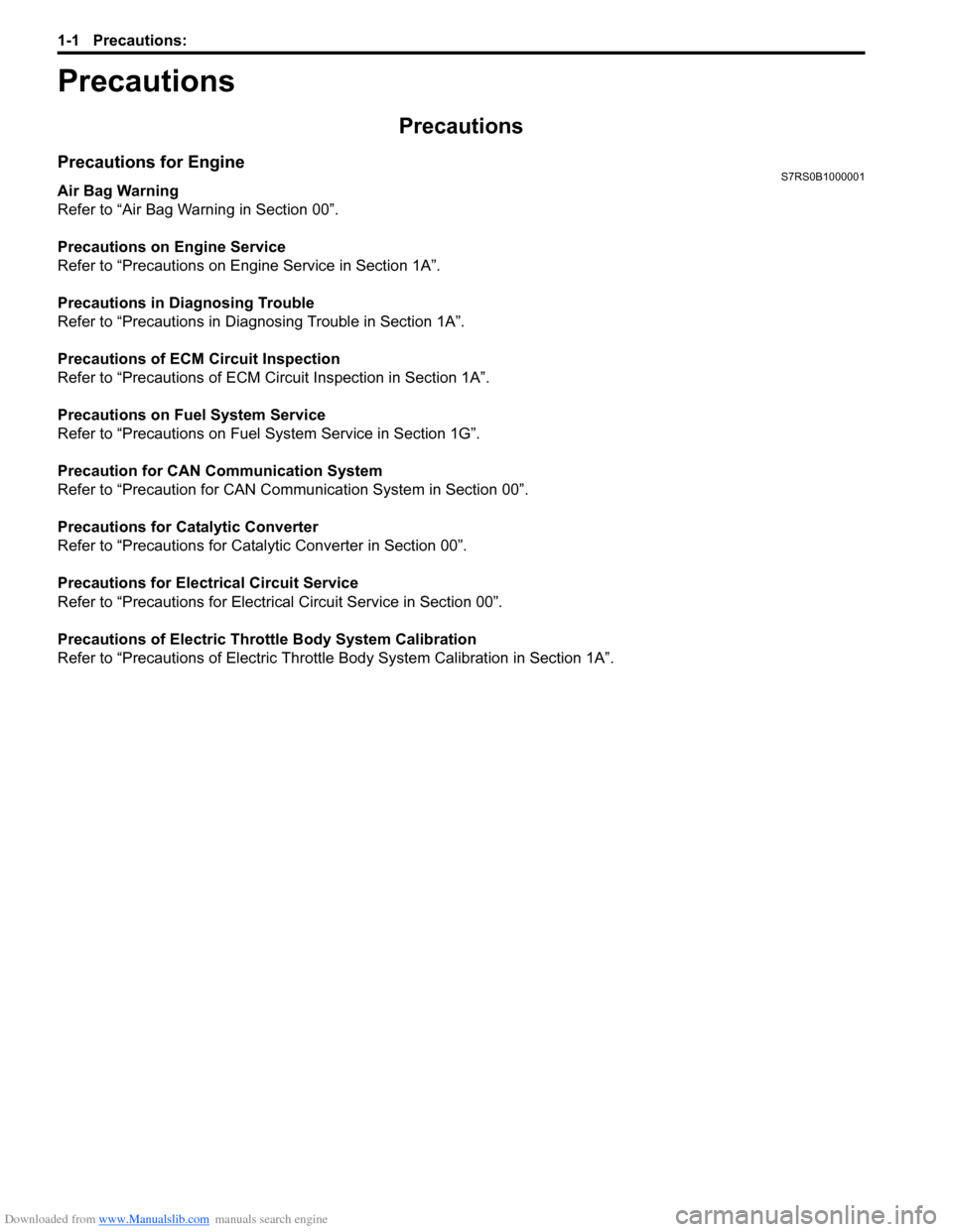
Precautions
Precautions
Precautions for EngineS7RS0B1000001
Air Bag Warning
Refer to “Air Bag Warning in Section 00”.
Precautions on Engine Service
Refer to “Precautions on Engine Service in Section 1A”.
Precautions in Diagnosing Trouble
Refer to “Precautions in Diagnosing Trouble in Section 1A”.
Precautions of ECM Circuit Inspection
Refer to “Precautions of ECM Circuit Inspection in Section 1A”.
Precautions on Fuel System Service
Refer to “Precautions on Fuel System Service in Section 1G”.
Precaution for CAN Communication System
Refer to “Precaution for CAN Communication System in Section 00”.
Precautions for Catalytic Converter
Refer to “Precautions for Catalytic Converter in Section 00”.
Precautions for Electrical Circuit Service
Refer to “Precautions for Electric al Circuit Service in Section 00”.
Precautions of Electric Throttle Body System Calibration
Refer to “Precautions of El ectric Throttle Body System Calibration in Section 1A”.