Torque SUZUKI SWIFT 2005 2.G Service Workshop Manual
[x] Cancel search | Manufacturer: SUZUKI, Model Year: 2005, Model line: SWIFT, Model: SUZUKI SWIFT 2005 2.GPages: 1496, PDF Size: 34.44 MB
Page 1170 of 1496

Downloaded from www.Manualslib.com manuals search engine 9-iv Table of Contents
Rear End Door Opener System Symptom Diagnosis .......................................................... 9F-5
Rear End Door Opener System Operation Inspection .......................................................... 9F-5
Repair Instructions ........... ................................... 9F-6
Front Door Lock Assembly Components ............ 9F-6
Front Door Lock Assembly Removal and Installation ......................................................... 9F-6
Front Door Lock Assembly Inspection ................ 9F-8
Power Door Lock Switch In spection.................... 9F-8
Door Key Cylinder Switch Inspection .................. 9F-8
Power Door Lock Actuator Inspection ................. 9F-9
Rear Door Lock Assembly Components ........... 9F-10
Rear Door Lock Assembly Removal and Installation ....................................................... 9F-10
Rear Door Lock Assembly Inspection ............... 9F-10
Rear End Door Lock Assembly Components.... 9F-11
Rear End Door Lock Assembly Removal and Installation ....................................................... 9F-11
Rear End Door Lock Assembly Inspection........ 9F-12
Rear End Door Opener Switch Inspection ........ 9F-12
Replacement of Transmitte r Battery ................. 9F-13
Programming Transmitter Code for Keyless Entry System (Vehicle without Keyless Start
System) ........................................................... 9F-13
Keyless Entry Answer Back Function
Change-over Procedure (If Equipped) ............ 9F-14
Keyless Entry Receiver Removal and
Installation ....................................................... 9F-14
Keyless Entry Receiver and Its Circuit Inspection ........................................................ 9F-15
Specifications .... ................................................. 9F-16
Tightening Torque Specifications ...................... 9F-16
Special Tools and Equipmen t ........................... 9F-16
Recommended Service Material ....................... 9F-16
Seats ............. ............................................ 9G-1
Repair Instructions ............................................. 9G-1
Front Seat Components ..................................... 9G-1
Front Seat Removal and In stallation .................. 9G-2
Rear Seat Components...................................... 9G-3
Rear Seat Removal and Installation................... 9G-4
Specifications .... .................................................. 9G-4
Tightening Torque Specifications ....................... 9G-4
Special Tools and Equipmen t ............................ 9G-4
Recommended Service Material ........................ 9G-4
Interior Trim ................. ............................ 9H-1
Repair Instructions ............ ..................................9H-1
Floor Carpet Removal and Installation ................9H-1
Head Lining Removal and Installation.................9H-1
Console Box Components ..................................9H-2
Specifications ..................... ..................................9H-3
Tightening Torque Specifications ........................9H-3
Hood / Fenders / Doors ...... ...................... 9J-1
Repair Instructions ............ .................................. 9J-1
Hood Removal and Installation ........................... 9J-1
Hood Inspection and Adjustment ........................ 9J-1
Front Fender Components .................................. 9J-2
Front Fender Removal and Installation ............... 9J-2
Front Door Assembly Comp onents ..................... 9J-3
Front Door Assembly Removal and Installation ......................................................... 9J-3
Rear Door Assembly Components...................... 9J-5
Rear Door Assembly Removal and Installation ......................................................... 9J-5
Rear End Door Assembly Components .............. 9J-6
Rear End Door Assembly Removal and Installation ......................................................... 9J-6
Specifications ..................... .................................. 9J-8
Tightening Torque Specifications ........................ 9J-8
Special Tools and Equipmen t ............................. 9J-8
Recommended Service Material ......................... 9J-8
Body Structure............... .......................... 9K-1
Repair Instructions ............ ..................................9K-1
Front Bumper and Rear Bumper Components .... 9K-1
Cowl Top Components........................................ 9K-2
Specifications ..................... ..................................9K-3
Body Dimensions ................................................ 9K-3
Panel Clearance................................................ 9K-10
Paint / Coatings ............. ...........................9L-1
General Description ............................................. 9L-1
Anti-Corrosion Treatment Construction............... 9L-1
Plastic Parts Finishing ......................................... 9L-2
Component Location ............ ............................... 9L-3
Sealant Application Areas ................................... 9L-3
Under Coating Application Areas ........................ 9L-8
Anti-Corrosion Compound Application Area ..... 9L-10
Exterior Trim ...... ...................................... 9M-1
Repair Instructions ......... .................................... 9M-1
Roof Molding Components................................. 9M-1
Splash Guard (If Equipped) Components .......... 9M-2
Page 1171 of 1496
Downloaded from www.Manualslib.com manuals search engine Precautions: 9-1
Body, Cab and Accessories
Precautions
Precautions
Precautions on Body, Cab and AccessoriesS7RS0B9000001
Air Bag Warning
Refer to “Air Bag Warning in Section 00”.
Fastener Caution
Refer to “Fastener Caution in Section 00”.
Precautions for Body Service
Refer to “Precautions for Body Service”.
Fastener Caution for Body Service:
Refer to “Fastener Caution for Body Service”.
Cautions in Body Electrical System Servicing
Refer to “Cautions in Body Electrical System Servicing in Section 9A”.
Precautions for Body ServiceS7RS0B9000002
WARNING!
For vehicles equipped with a Supplemental Restraint (Air Bag) System:
When servicing vehicle body, if shock may be applied to air bag system component parts, remove
those parts beforehand.
Fastener Caution for Body ServiceS7RS0B9000003
CAUTION!
• Fasteners are important attaching parts in that they could affect the performance of vital
components and systems, and/or could result in major repair expense. They must be replaced with
one of the same part number of with an equivalent part if replacement become necessary.
• Do not use a replacement part of lesser quality or substitute a design. Torque values must be used as specified during reassembly to assure proper retention of these parts.
Page 1187 of 1496
Downloaded from www.Manualslib.com manuals search engine Wiring Systems: 9A-16
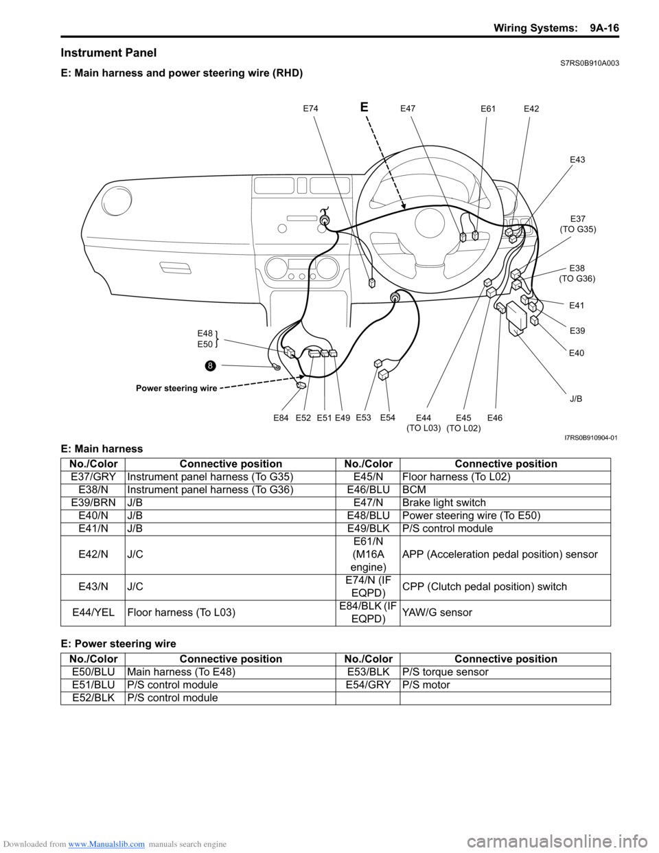
Instrument PanelS7RS0B910A003
E: Main harness and power steering wire (RHD)
E: Main harness
E: Power steering wire
J/B
E54
E53
E49
E51E52E84
E48
E50
Power steering wire
E47E74E42E61
E43
E45
(TO L02)
E44
(TO L03)E46
E40 E39
E41 E37
(TO G35)
E38
(TO G36)
8
E
I7RS0B910904-01
No./Color Connective position No./ColorConnective position
E37/GRY Instrument panel harness (To G35) E45/N Floor harness (To L02)
E38/N Instrument panel harness (To G36) E46/BLU BCM
E39/BRN J/B E47/N Brake light switch
E40/N J/B E48/BLU Power steering wire (To E50)
E41/N J/B E49/BLK P/S control module
E42/N J/C E61/N
(M16A
engine) APP (Acceleration pedal position) sensor
E43/N J/C E74/N (IF
EQPD) CPP (Clutch pedal position) switch
E44/YEL Floor harness (To L03) E84/BLK (IF
EQPD) YAW/G sensor
No./Color Connective position No./ColorConnective position
E50/BLU Main harness (To E48) E53/BLK P/S torque sensor
E51/BLU P/S control module E54/GRY P/S motor
E52/BLK P/S control module
Page 1188 of 1496
Downloaded from www.Manualslib.com manuals search engine 9A-17 Wiring Systems:
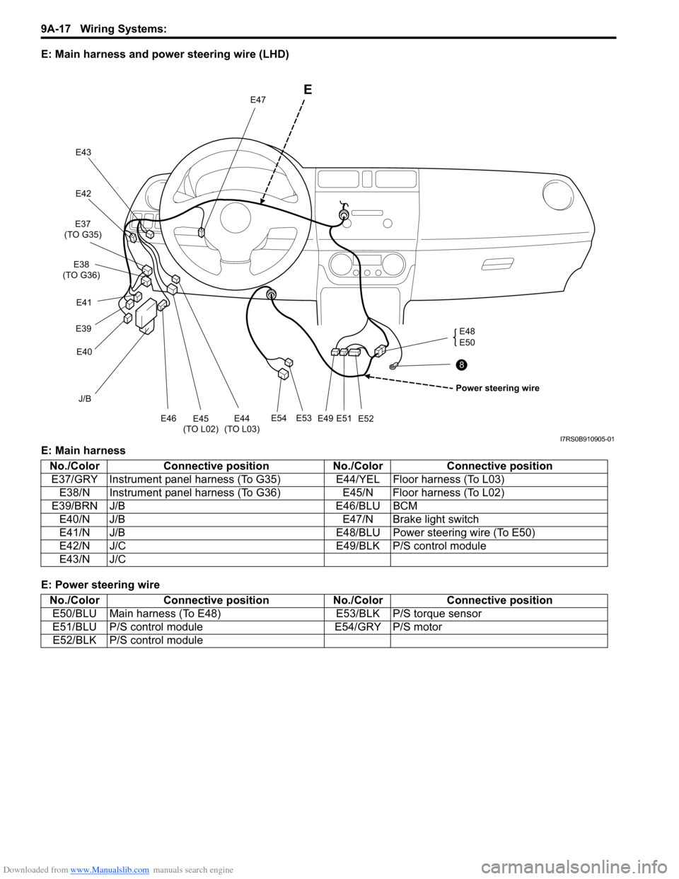
E: Main harness and power steering wire (LHD)
E: Main harness
E: Power steering wire
J/B
E54E53
E49E51E52 E48
E50
E
Power steering wire
E47
E43
E42
E45
(TO L02) E44
(TO L03)E46
E40
E39 E41
E37
(TO G35)
E38
(TO G36)
8
I7RS0B910905-01
No./Color Connective position No./ColorConnective position
E37/GRY Instrument panel harness (T o G35)E44/YEL Floor harness (To L03)
E38/N Instrument panel harness (To G36) E45/N Floor harness (To L02)
E39/BRN J/B E46/BLU BCM
E40/N J/B E47/N Brake light switch
E41/N J/B E48/BLU Power steering wire (To E50)
E42/N J/C E49/BLK P/S control module
E43/N J/C
No./Color Connective position No./ColorConnective position
E50/BLU Main harness (To E48) E53/BLK P/S torque sensor
E51/BLU P/S control module E54/GRY P/S motor
E52/BLK P/S control module
Page 1270 of 1496
Downloaded from www.Manualslib.com manuals search engine 9A-99 Wiring Systems:
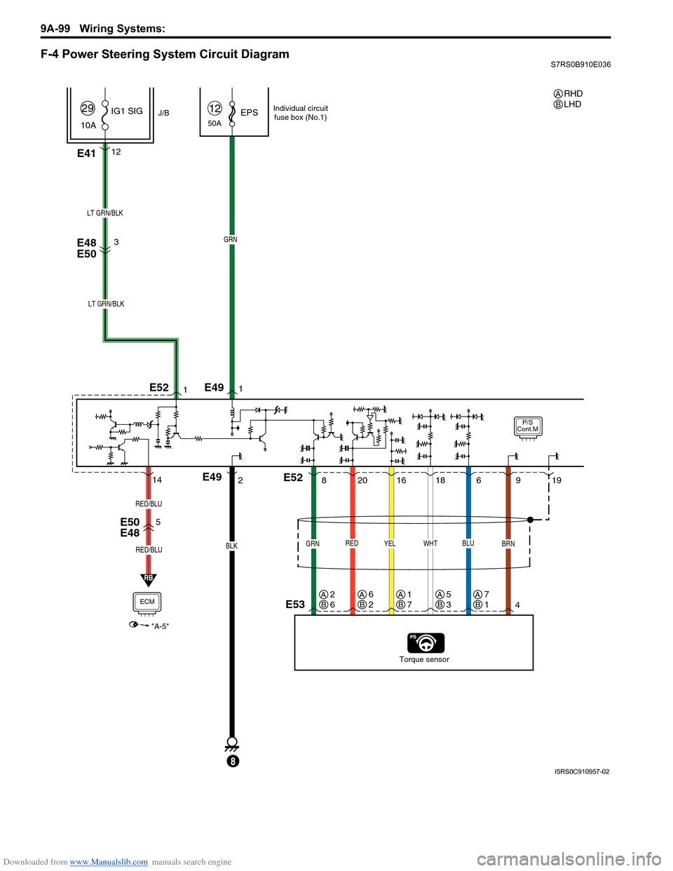
F-4 Power Steering System Circuit DiagramS7RS0B910E036
P/S
Cont.M
50AEPS12
E4112
J/B
10A IG1 SIG
29
RED
20
E48
E50
E50
E48
Torque sensor
BLK
E49
8
GRN
LT GRN/BLK
YEL
16
GRN
8
BRN
49
WHT
18
BLU
619
1
21
LT GRN/BLK
3
E53
E49
E52
E52
RB
5
ECM
"A-5"
RED/BLU
RED/BLU
14
Individual circuit
fuse box (No.1)
RHD
LHDAB
AB2
6AB6
2AB1
7AB5
3AB7
1
I5RS0C910957-02
Page 1314 of 1496
Downloaded from www.Manualslib.com manuals search engine 9C-19 Instrumentation / Driver Info. / Horn:
Installation
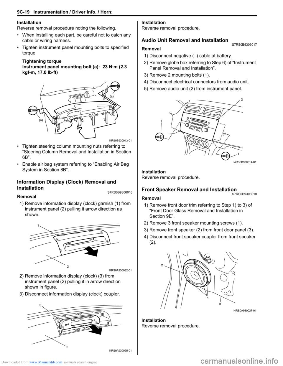
Reverse removal procedure noting the following.
• When installing each part, be careful not to catch any
cable or wiring harness.
• Tighten instrument panel mounting bolts to specified
torque
Tightening torque
Instrument panel mounting bolt (a): 23 N·m (2.3
kgf-m, 17.0 lb-ft)
• Tighten steering column mounting nuts referring to “Steering Column Removal an d Installation in Section
6B”.
• Enable air bag system referring to “Enabling Air Bag System in Section 8B”.
Information Display (Clock) Removal and
Installation
S7RS0B9306016
Removal
1) Remove information display (clock) garnish (1) from instrument panel (2) pulling it arrow direction as
shown.
2) Remove information di splay (clock) (3) from
instrument panel (2) pulli ng it in arrow direction
shown in figure.
3) Disconnect information display (clock) coupler. Installation
Reverse removal procedure.
Audio Unit Removal and InstallationS7RS0B9306017
Removal
1) Disconnect negative (–) cable at battery.
2) Remove globe box referring to Step 6) of “Instrument Panel Removal and Installation”.
3) Remove 2 mounting bolts (1).
4) Disconnect electrical connectors from audio unit.
5) Remove audio unit (2) from instrument panel.
Installation
Reverse removal procedure.
Front Speaker Removal and InstallationS7RS0B9306018
Removal 1) Remove front door trim refe rring to Step 1) to 3) of
“Front Door Glass Remo val and Installation in
Section 9E”.
2) Remove 3 front speaker mounting screws (1).
3) Remove front speaker (2) from front door panel (3).
4) Disconnect front speaker coupler from front speaker (2).
Installation
Reverse removal procedure.
(a) (a)
I4RS0B930013-01
1
2I4RS0A930032-01
3
2I4RS0A930025-01
2
1
1
I4RS0B930014-01
1
2
3
I4RS0A930027-01
Page 1316 of 1496
Downloaded from www.Manualslib.com manuals search engine 9C-21 Instrumentation / Driver Info. / Horn:
Antenna Amplifier Removal and InstallationS7RS0B9306023
NOTE
Antenna amplifier incorporated with antenna
base.
Removal1) Remove head lining referring to “Head Lining Removal and Installa tion in Section 9H”.
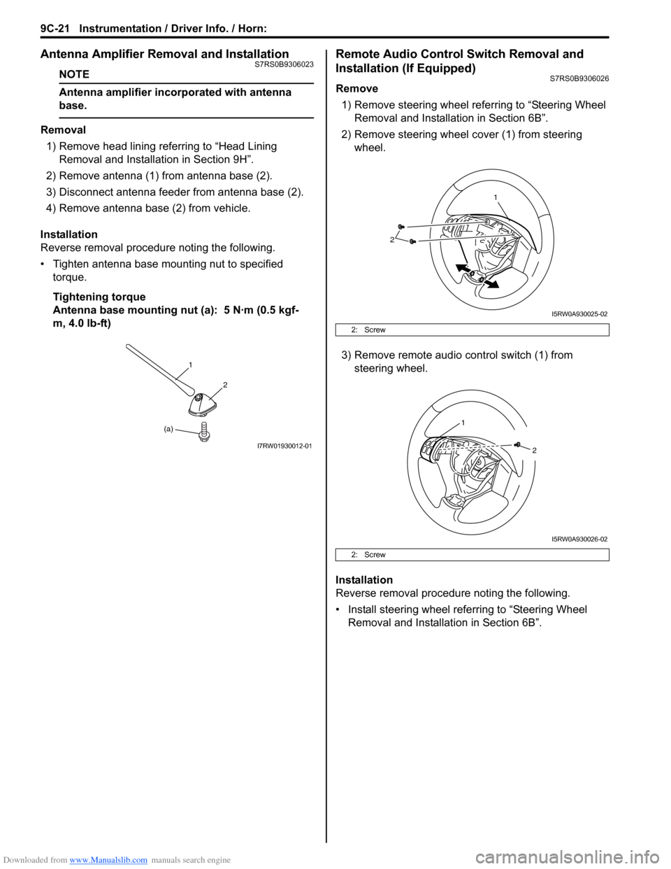
2) Remove antenna (1) from antenna base (2).
3) Disconnect antenna feeder from antenna base (2).
4) Remove antenna base (2) from vehicle.
Installation
Reverse removal procedure noting the following.
• Tighten antenna base mounting nut to specified torque.
Tightening torque
Antenna base mounting nut (a): 5 N·m (0.5 kgf-
m, 4.0 lb-ft)
Remote Audio Control Switch Removal and
Installation (If Equipped)
S7RS0B9306026
Remove
1) Remove steering wheel re ferring to “Steering Wheel
Removal and Installati on in Section 6B”.
2) Remove steering wheel cover (1) from steering wheel.
3) Remove remote audio control switch (1) from steering wheel.
Installation
Reverse removal procedure noting the following.
• Install steering wheel referring to “Steering Wheel Removal and Installati on in Section 6B”.
(a)1
2
I7RW01930012-01
2: Screw
2: Screw
2
1
I5RW0A930025-02
1
2
I5RW0A930026-02
Page 1317 of 1496
Downloaded from www.Manualslib.com manuals search engine Instrumentation / Driver Info. / Horn: 9C-22
Remote Audio Control Switch Inspection (If
Equipped)
S7RS0B9306024
1) Remove driver air bag (inflator) module referring to
“Driver Air Bag (Inflator) Module Removal and
Installation in Section 8B”.
2) Disconnect remote audio control switch connector
from contact coil.
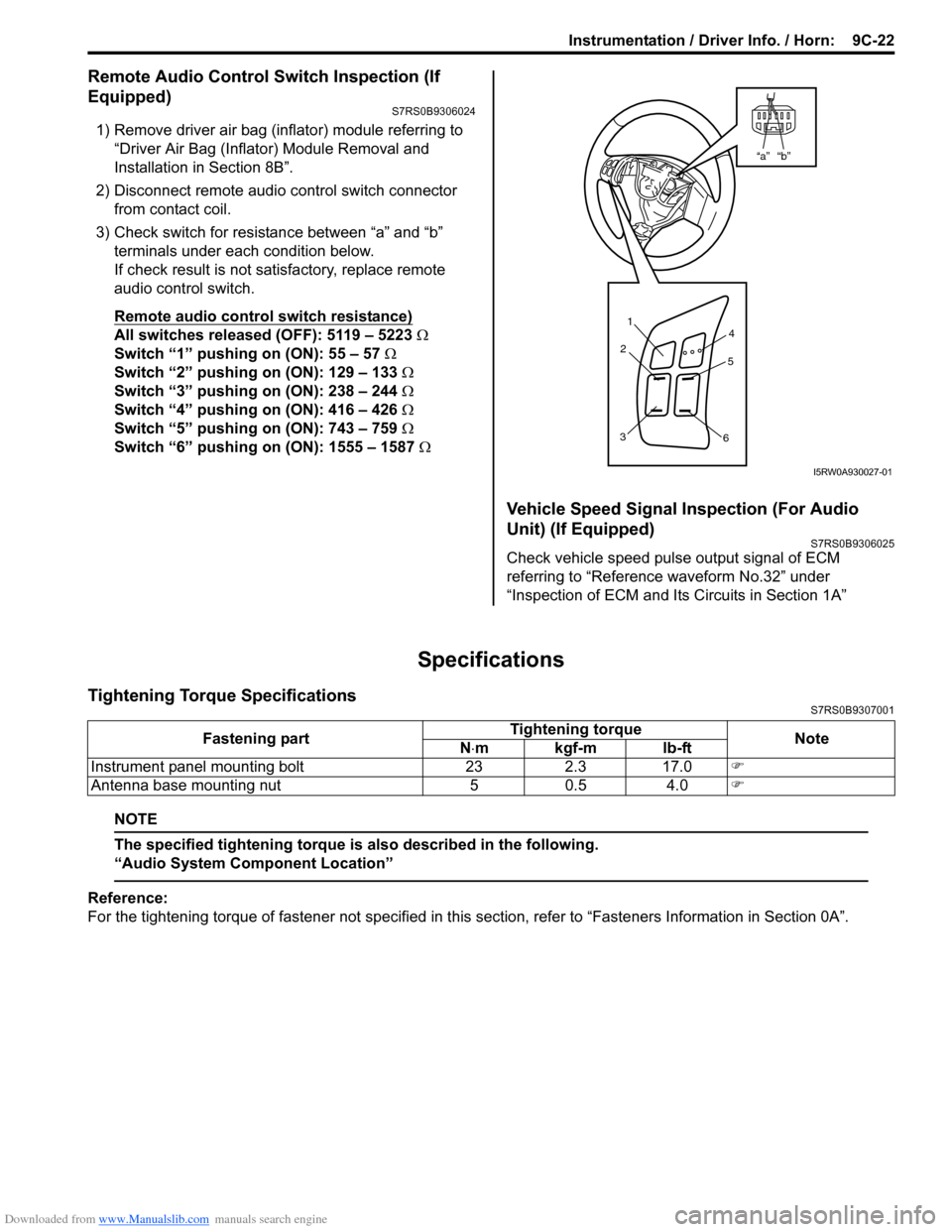
3) Check switch for resistance between “a” and “b” terminals under each condition below.
If check result is not satisfactory, replace remote
audio control switch.
Remote audio control switch resistance)
All switches released (OFF): 5119 – 5223 Ω
Switch “1” pushing on (ON): 55 – 57 Ω
Switch “2” pushing on (ON): 129 – 133 Ω
Switch “3” pushing on (ON): 238 – 244 Ω
Switch “4” pushing on (ON): 416 – 426 Ω
Switch “5” pushing on (ON): 743 – 759 Ω
Switch “6” pushing on (ON): 1555 – 1587 Ω
Vehicle Speed Signal Inspection (For Audio
Unit) (If Equipped)
S7RS0B9306025
Check vehicle speed pulse output signal of ECM
referring to “Reference waveform No.32” under
“Inspection of ECM and Its Circuits in Section 1A”
Specifications
Tightening Torque SpecificationsS7RS0B9307001
NOTE
The specified tightening torque is also described in the following.
“Audio System Component Location”
Reference:
For the tightening torque of fastener not specified in this section, refer to “Fasteners Information in Section 0A”.
“b”“a”
1
2
3 4
5
6
I5RW0A930027-01
Fastening part Tightening torque
Note
N ⋅mkgf-mlb-ft
Instrument panel mounting bolt 23 2.3 17.0 �)
Antenna base mounting nut 5 0.5 4.0 �)
Page 1320 of 1496
Downloaded from www.Manualslib.com manuals search engine 9D-3 Wipers / Washers:
Washer Tank and Washer Pump Removal and
Installation
S7RS0B9406002
Removal1) Disconnect negative (–) cable at battery.
2) Remove front bumper referring to “Front Bumper and Rear Bumper Components in Section 9K”.
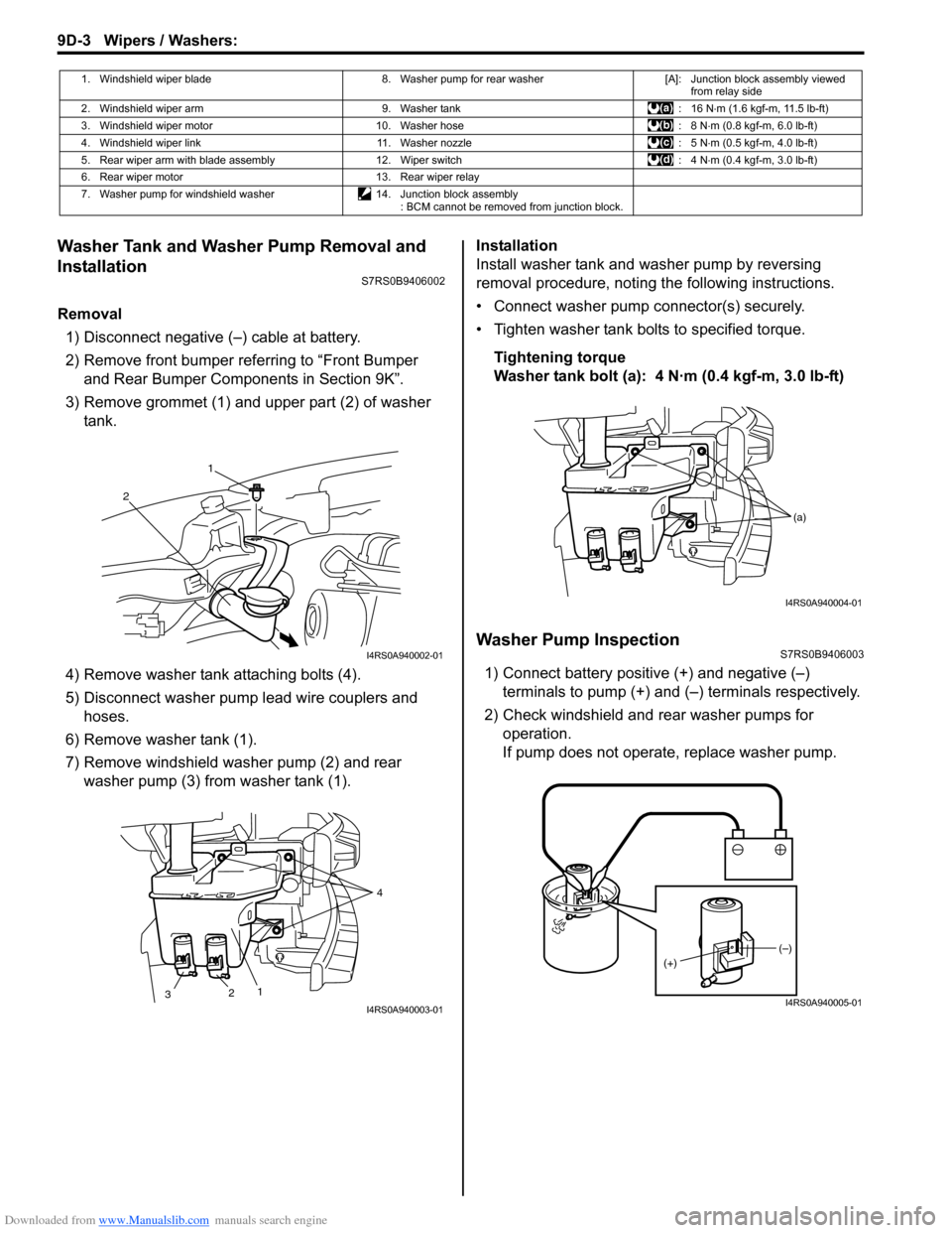
3) Remove grommet (1) and upper part (2) of washer tank.
4) Remove washer tank attaching bolts (4).
5) Disconnect washer pump lead wire couplers and hoses.
6) Remove washer tank (1).
7) Remove windshield washer pump (2) and rear washer pump (3) from washer tank (1). Installation
Install washer tank and washer pump by reversing
removal procedure, noting the following instructions.
• Connect washer pump connector(s) securely.
• Tighten washer tank bolts to specified torque.
Tightening torque
Washer tank bolt (a): 4 N·m (0.4 kgf-m, 3.0 lb-ft)
Washer Pump InspectionS7RS0B9406003
1) Connect battery positive (+) and negative (–) terminals to pump (+) and (–) terminals respectively.
2) Check windshield and rear washer pumps for
operation.
If pump does not operate, replace washer pump.
1. Windshield wiper blade 8. Washer pump for rear washer[A]: Junction block assembly viewed
from relay side
2. Windshield wiper arm 9. Washer tank: 16 N⋅m (1.6 kgf-m, 11.5 lb-ft)
3. Windshield wiper motor 10. Washer hose : 8 N⋅m (0.8 kgf-m, 6.0 lb-ft)
4. Windshield wiper link 11. Washer nozzle : 5 N⋅m (0.5 kgf-m, 4.0 lb-ft)
5. Rear wiper arm with blade assembly 12. Wiper switch : 4 N⋅m (0.4 kgf-m, 3.0 lb-ft)
6. Rear wiper motor 13. Rear wiper relay
7. Washer pump for windshield washer 14. Junction block assembly
: BCM cannot be removed from junction block.
1
2
I4RS0A940002-01
2 1 4
3
I4RS0A940003-01
(a)
I4RS0A940004-01
(–)
(+)
I4RS0A940005-01
Page 1321 of 1496
Downloaded from www.Manualslib.com manuals search engine Wipers / Washers: 9D-4
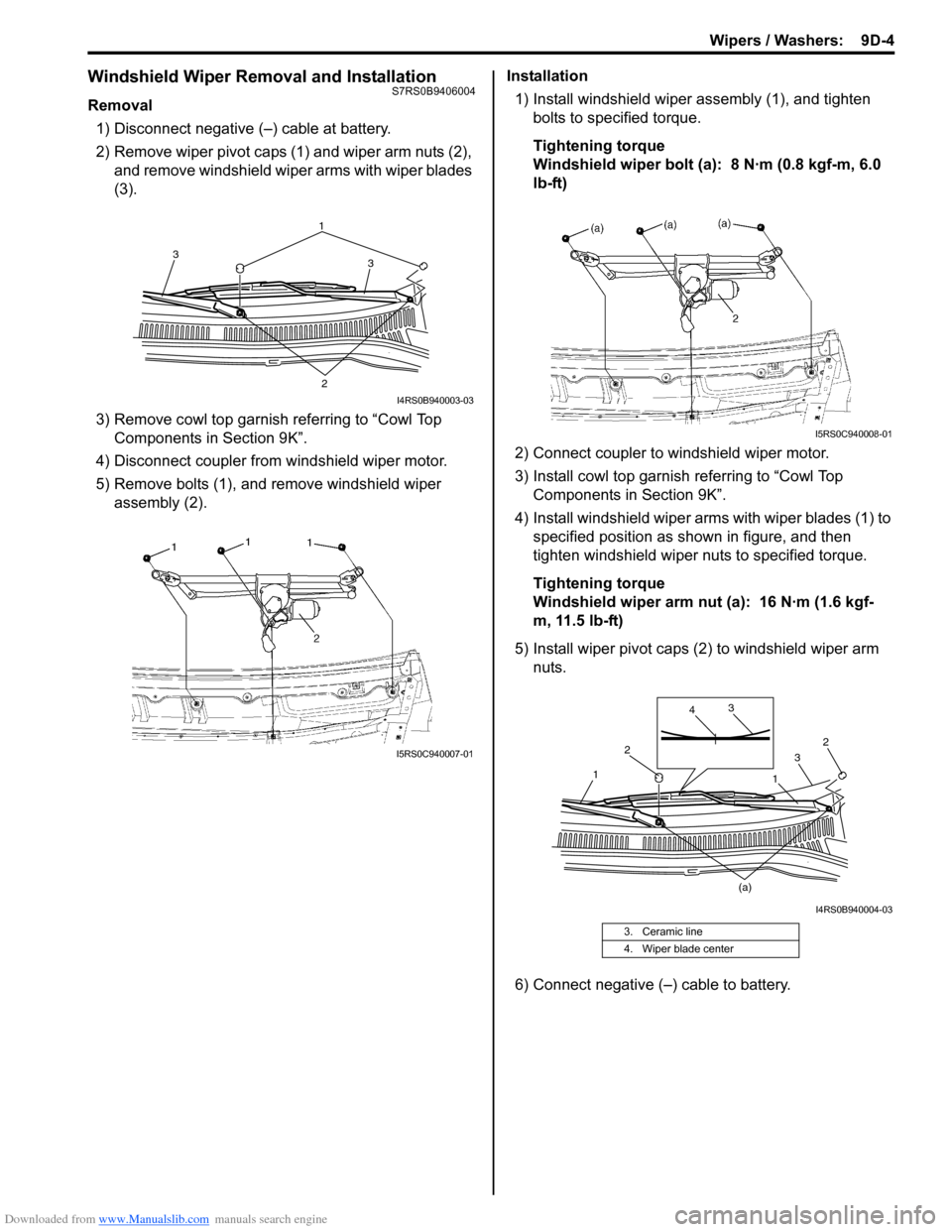
Windshield Wiper Removal and InstallationS7RS0B9406004
Removal1) Disconnect negative (–) cable at battery.
2) Remove wiper pivot caps (1) and wiper arm nuts (2), and remove windshield wiper arms with wiper blades
(3).
3) Remove cowl top garnish referring to “Cowl Top Components in Section 9K”.
4) Disconnect coupler from windshield wiper motor.
5) Remove bolts (1), and remove windshield wiper assembly (2). Installation
1) Install windshield wiper assembly (1), and tighten bolts to specified torque.
Tightening torque
Windshield wiper bolt (a): 8 N·m (0.8 kgf-m, 6.0
lb-ft)
2) Connect coupler to windshield wiper motor.
3) Install cowl top garnish referring to “Cowl Top
Components in Section 9K”.
4) Install windshield wiper arms with wiper blades (1) to specified position as shown in figure, and then
tighten windshield wiper nuts to specified torque.
Tightening torque
Windshield wiper arm nut (a): 16 N·m (1.6 kgf-
m, 11.5 lb-ft)
5) Install wiper pivot caps (2 ) to windshield wiper arm
nuts.
6) Connect negative (–) cable to battery.
1 3
3
2
I4RS0B940003-03
I5RS0C940007-01
3. Ceramic line
4. Wiper blade center
I5RS0C940008-01
2
2 3
3
4
1
1
(a)
I4RS0B940004-03