air cond SUZUKI SWIFT 2005 2.G Service Owner's Manual
[x] Cancel search | Manufacturer: SUZUKI, Model Year: 2005, Model line: SWIFT, Model: SUZUKI SWIFT 2005 2.GPages: 1496, PDF Size: 34.44 MB
Page 59 of 1496
Downloaded from www.Manualslib.com manuals search engine Engine General Information and Diagnosis: 1A-9
Air Intake System DescriptionS7RS0B1101006
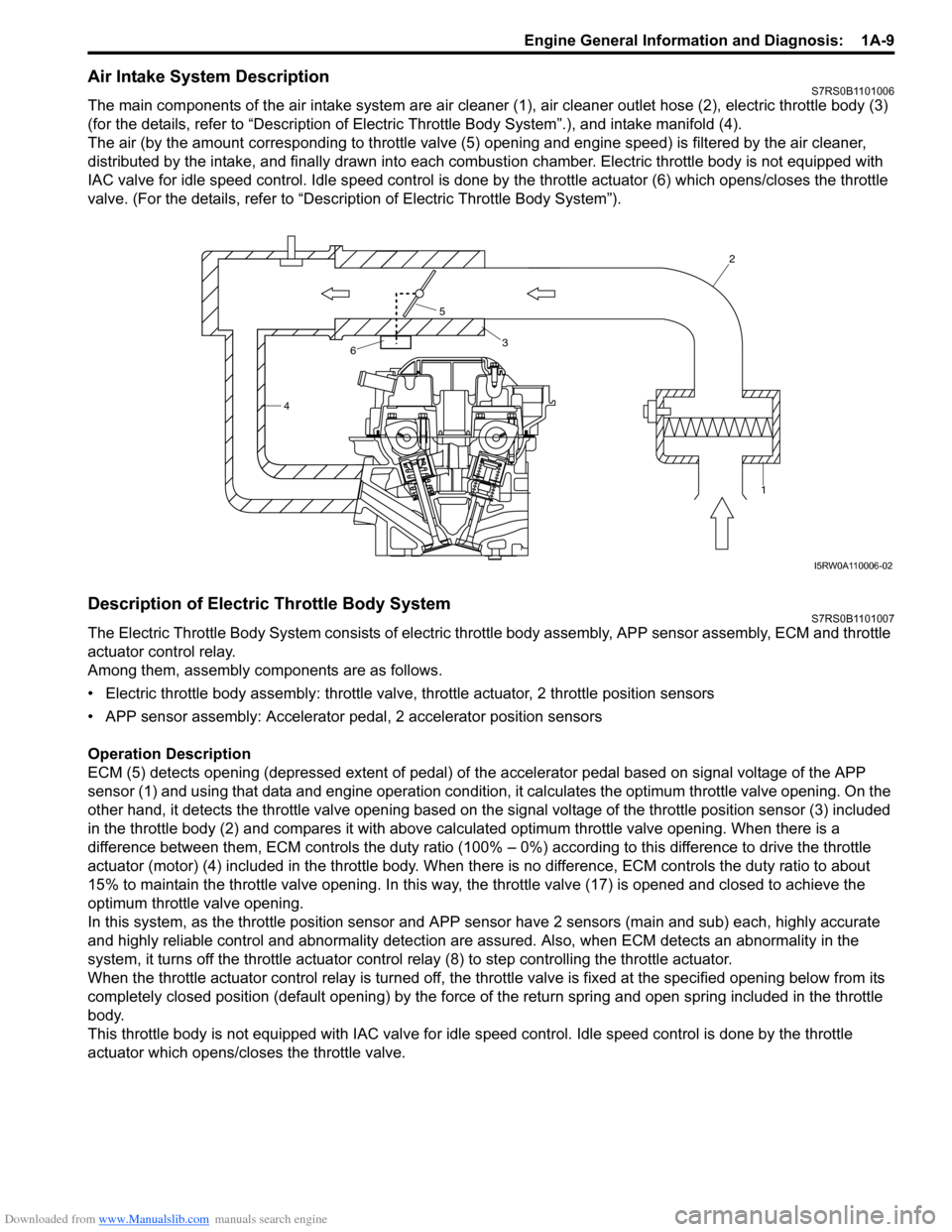
The main components of the air intake system are air cleaner (1), air cleaner outlet hose (2), electric throttle body (3)
(for the details, refer to “Description of Electric Throttle Body System”.), and intake manifold (4).
The air (by the amount corresponding to throttle valve (5) opening and engine speed) is filtered by the air cleaner,
distributed by the intake, and finally drawn into each combusti on chamber. Electric throttle body is not equipped with
IAC valve for idle speed control. Idle speed control is done by the throttle actuator (6) which opens/closes the throttle
valve. (For the details, refer to “Description of Electric Throttle Body System”).
Description of Electric Throttle Body SystemS7RS0B1101007
The Electric Throttle Body System consists of electric throttle body asse mbly, APP sensor assembly, ECM and throttle
actuator control relay.
Among them, assembly components are as follows.
• Electric throttle body assembly: throttle valve, throttle actuator, 2 throttle position sensors
• APP sensor assembly: Accelerator pe dal, 2 accelerator position sensors
Operation Description
ECM (5) detects opening (depressed extent of pedal) of the accelerator pedal based on signal voltage of the APP
sensor (1) and using that data and engi ne operation condition, it calculates the optimum throttle valve opening. On the
other hand, it detects the throttle valve opening based on the signal voltage of the throttle position sensor (3) included
in the throttle body (2) and compares it with above calculated optimum throttle valve opening. When there is a
difference between them, ECM controls the duty ratio (100% – 0%) according to this difference to drive the throttle
actuator (motor) (4) included in the throttle body. When th ere is no difference, ECM controls the duty ratio to about
15% to maintain the throttle valve opening . In this way, the throttle valve (17) is opened and closed to achieve the
optimum throttle valve opening.
In this system, as the thrott le position sensor and APP sensor have 2 sensors (main and sub) each, highly accurate
and highly reliable control and abnormality detection are assured. Also, when ECM detects an abnormality in the
system, it turns off the th rottle actuator control relay (8) to step controlling the throttle actuator.
When the throttle actuator control relay is turned off, the throttle valve is fixed at the specified opening below from its
completely closed position (default openin g) by the force of the return spring and open spring included in the throttle
body.
This throttle body is not equipped with IAC valve for idle speed control. Idle speed control is done by the throttle
actuator which opens/closes the throttle valve.
4 2
1
3
5
6
I5RW0A110006-02
Page 72 of 1496
Downloaded from www.Manualslib.com manuals search engine 1A-22 Engine General Information and Diagnosis:
Diagnostic Information and Procedures
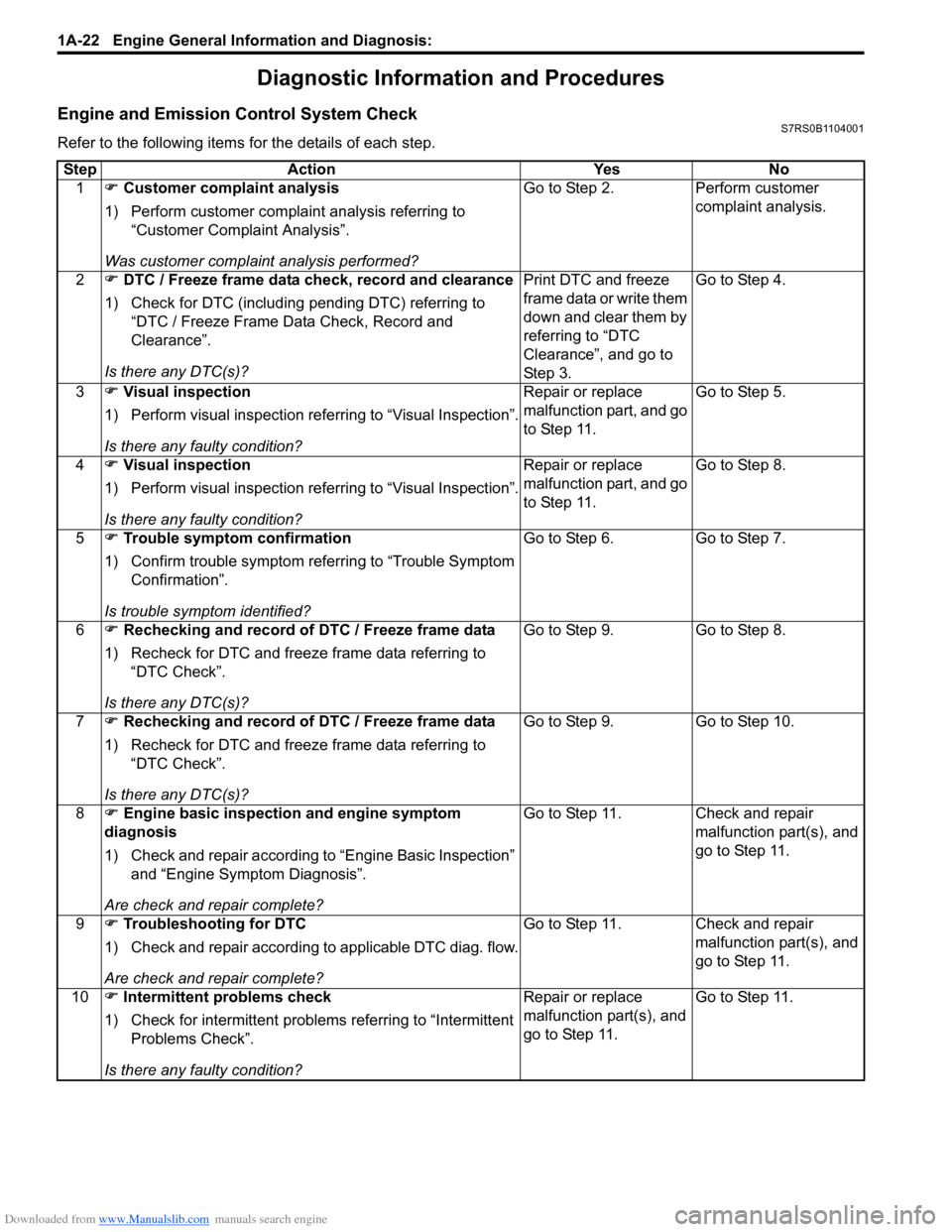
Engine and Emission Control System CheckS7RS0B1104001
Refer to the following items for the details of each step.Step Action Yes No 1 �) Customer complaint analysis
1) Perform customer complaint analysis referring to “Customer Complaint Analysis”.
Was customer complaint analysis performed? Go to Step 2. Perform customer
complaint analysis.
2 �) DTC / Freeze frame data check, record and clearance
1) Check for DTC (including pending DTC) referring to “DTC / Freeze Frame Data Check, Record and
Clearance”.
Is there any DTC(s)? Print DTC and freeze
frame data or write them
down and clear them by
referring to “DTC
Clearance”, and go to
St ep 3 .Go to Step 4.
3 �) Visual inspection
1) Perform visual inspection referring to “Visual Inspection”.
Is there any faulty condition? Repair or replace
malfunction part, and go
to Step 11.
Go to Step 5.
4 �) Visual inspection
1) Perform visual inspection referring to “Visual Inspection”.
Is there any faulty condition? Repair or replace
malfunction part, and go
to Step 11.
Go to Step 8.
5 �) Trouble symptom confirmation
1) Confirm trouble symptom referring to “Trouble Symptom Confirmation”.
Is trouble symptom identified? Go to Step 6.
Go to Step 7.
6 �) Rechecking and record of DTC / Freeze frame data
1) Recheck for DTC and freeze frame data referring to “DTC Check”.
Is there any DTC(s)? Go to Step 9.
Go to Step 8.
7 �) Rechecking and record of DTC / Freeze frame data
1) Recheck for DTC and freeze frame data referring to “DTC Check”.
Is there any DTC(s)? Go to Step 9.
Go to Step 10.
8 �) Engine basic inspection and engine symptom
diagnosis
1) Check and repair according to “Engine Basic Inspection”
and “Engine Symptom Diagnosis”.
Are check and repair complete? Go to Step 11. Check and repair
malfunction part(s), and
go to Step 11.
9 �) Troubleshooting for DTC
1) Check and repair according to applicable DTC diag. flow.
Are check and repair complete? Go to Step 11. Check and repair
malfunction part(s), and
go to Step 11.
10 �) Intermittent problems check
1) Check for intermittent problems referring to “Intermittent Problems Check”.
Is there any faulty condition? Repair or replace
malfunction part(s), and
go to Step 11.
Go to Step 11.
Page 75 of 1496
Downloaded from www.Manualslib.com manuals search engine Engine General Information and Diagnosis: 1A-25
Step 2: DTC / Freeze Frame Data Check, Record and
Clearance
First, check DTC (including pending DTC), referring to
“DTC Check”. If DTC is indicated, print it and freeze
frame data or write them down and then clear them by
referring to “DTC Clearance”. DTC indicates malfunction
that occurred in the system but does not indicate
whether it exists now or it occurred in the past and the
normal condition has been restored now. To check which
case applies, check the sy mptom in question according
to Step 5 and recheck DTC according to Step 6 and 7.
Attempt to diagnose a trouble based on DTC in this step
only or failure to clear the DTC in this step will lead to
incorrect diagnosis, trouble diagnosis of a normal circuit
or difficulty in troubleshooting.
Step 3 and 4: Visual Inspection
As a preliminary step, be sure to perform visual check of
the items that support proper function of the engine
referring to “Visual Inspection”.
Step 5: Trouble Symptom Confirmation
Based on information obtained in “Step 1: Customer
Complaint Analysis: ” and “Step 2: DTC / Freeze Frame
Data Check, Record and Clearance: ”, confirm trouble
symptoms. Also, reconfirm DTC according to “DTC
Confirmation Procedure” described in each DTC diag.
flow.
Step 6 and 7: Rechecking and Record of DTC /
Freeze Frame Data
Refer to “DTC Check” for checking procedure.
Step 8: Engine Basic Inspection and Engine
Symptom Diagnosis
Perform basic engine check according to “Engine Basic
Inspection” first. When the end of the flow has been
reached, check the parts of the system suspected as a
possible cause referring to “Engine Symptom Diagnosis”
and based on symptoms appearing on the vehicle
(symptoms obtained through steps of customer
complaint analysis, trouble symptom confirmation and/or
basic engine check) and repair or replace faulty parts, if
any.
Step 9: Troubleshooting for DTC (See each DTC
Diag. Flow)
Based on the DTC indicated in Step 6 or 7 and referring
to the applicable DTC diag. flow, locate the cause of the
trouble, namely in a sensor, switch, wire harness,
connector, actuator, ECM or other part and repair or
replace faulty parts. Step 10: Intermittent Problems Check
Check parts where an intermit
tent trouble is easy to
occur (e.g., wire harness, connector, etc.), referring to
“Intermittent and Poor Connec tion Inspection in Section
00” and related circuit of DTC recorded in Step 2.
Step 11: Final Confirmation Test
Confirm that the problem symptom has gone and the
engine is free from any abnormal conditions. If what has
been repaired is re lated to the DTC, clear the DTC once,
perform DTC confirmation procedure and confirm that no
DTC is indicated.
Malfunction Indicator Lamp (MIL) CheckS7RS0B1104002
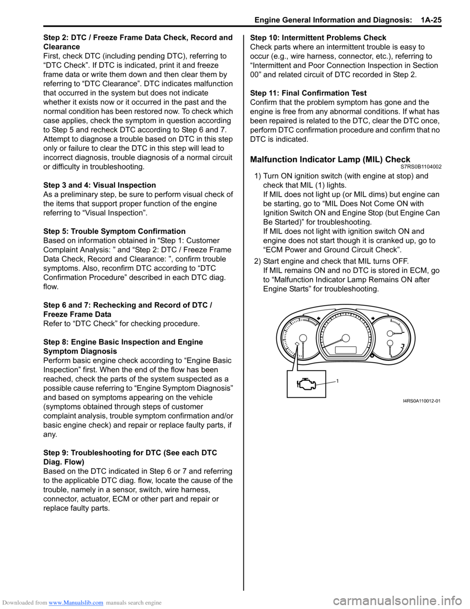
1) Turn ON ignition switch (with engine at stop) and check that MIL (1) lights.
If MIL does not light up (or MIL dims) but engine can
be starting, go to “MIL Does Not Come ON with
Ignition Switch ON and Engine Stop (but Engine Can
Be Started)” for troubleshooting.
If MIL does not light with ignition switch ON and
engine does not start though it is cranked up, go to
“ECM Power and Ground Circuit Check”.
2) Start engine and check that MIL turns OFF. If MIL remains ON and no DTC is stored in ECM, go
to “Malfunction Indicator Lamp Remains ON after
Engine Starts” for troubleshooting.
1
I4RS0A110012-01
Page 78 of 1496
Downloaded from www.Manualslib.com manuals search engine 1A-28 Engine General Information and Diagnosis:
�) *P0031 HO2S heater control circuit low
(Sensor-1) Heater voltage is less than specification while heater ON. 2 driving
cycles
�) *P0032 HO2S heater control circuit
high (Sensor-1) Heater voltage is more than
specification while heater
ON. 2 driving
cycles
�) *P0037 HO2S heater control circuit low
(Sensor-2) Heater voltage is less than specification while heater ON. 2 driving
cycles
�) *P0038 HO2S heater control circuit
high (Sensor-2) Heater voltage is more than
specification while heater
ON. 2 driving
cycles
�)
�U *P0101 Mass or volume air flow circuit
range/performance MAF sensor volume is more
than specification or less
than specification. 2 driving
cycles
�) *P0102 Mass or volume air flow circuit
low input Output voltage of MAF sensor is less than specification. 1 driving
cycle
�) *P0103 Mass or volume air flow circuit
high input Output voltage of MAF sensor is more than specification. 1 driving
cycle
�)
�U *P0106 Manifold absolute pressure/
barometric pressure circuit
range/performance Difference between Max. manifold absolute pressure
value and Min. manifold pressure value is less than
specification or difference between barometric pressure
value and manifold pressure value is less than
specification
2 driving
cycles
�) *P0107 Manifold absolute pressure/
barometric pressure circuit low
input Output voltage of MAP sensor
is less than specification.1 driving
cycle
�) *P0108 Manifold absolute pressure/
barometric pressure circuit high
input Output voltage of MAP sensor is more than specification.
1 driving
cycle
�)
�U *P0111 Intake air temperature sensor 1
circuit range/performance Variation of intake air temperature from engine start is
less than specification. 2 driving
cycles
�) *P0112 Intake air temperature sensor 1
circuit low Circuit voltage of IAT sensor is less than specification. 1 driving
cycle
�) *P0113 Intake air temperature sensor 1
circuit hig
h Circuit voltage of IAT sensor
is more than specification. 1 driving
cycle
�)
�U *P0116 Engine coolant temperature
circuit range/performance Engine coolant temperature is less than specified
temperature for specified time from engine start. 2 driving
cycles
�) *P0117 Engine coolant temperature
circuit low Circuit voltage of ECT sensor
is less than specification. 1 driving
cycle
�) *P0118 Engine coolant temperature
circuit high Circuit voltage of ECT sensor
is more than specification. 1 driving
cycle
�) *P0122 Throttle/pedal position sensor/
switch “A” circuit low Output voltage of TP sensor (main) is lower than
specification. 1 driving
cycle
�) *P0123 Throttle/pedal position sensor/
switch “A” circuit high Output voltage of TP sensor (main) is higher than
specification. 1 driving
cycle
�)
�U *P0131 O2 sensor (HO2S) circuit low
voltage (Sensor-1)
Max. output voltage of HO2S-1
is less than specification.2 driving
cycles
�)
�U *P0132 O2 sensor (HO2S) circuit high
voltage (Sensor-1)
Min. output voltage of HO2S-1
is more than specification. 2 driving
cycles
�)
�U *P0133 O2 sensor (HO2S) circuit slow
response (Sensor-1) Response time of HO2S-1 output voltage between rich
and lean is longer than specification. 2 driving
cycles
�) *P0134 O2 sensor (HO2S) circuit no
activity detected (Sensor-1) Output voltage of HO2S-1 is
more than specification or
less than specification. (or HO2S-1 circuit open or short) 2 driving
cycles
�)
�U *P0137 O2 sensor (HO2S) circuit low
voltage (Sensor-2) Output voltage of HO2S-2 is
less than specification while
engine is idling after driving with high engine load and
Max. output voltage of HO2S-2 minus Min. output voltage
of HO2S-2 is less than specification. 2 driving
cycles
�)
�U *P013
8 O2 sensor (HO2S) circuit high
voltage (Sensor-2) Output voltage of HO2S-2 is
more than specification while
engine is idling after driving with high engine load and
Max. output voltage of HO2S-2 minus Min. output voltage
of HO2S-2 is less than specification. 2 driving
cycles
DTC No. Detecting item
Detecting condition
(DTC will set when detecting:) MIL
Page 81 of 1496
Downloaded from www.Manualslib.com manuals search engine Engine General Information and Diagnosis: 1A-31
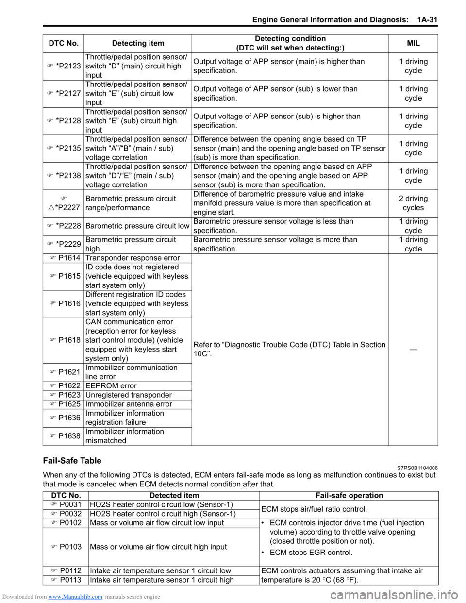
Fail-Safe TableS7RS0B1104006
When any of the following DTCs is detected, ECM enters fail-safe mode as long as malfunction continues to exist but
that mode is canceled when ECM de tects normal condition after that.
�)
*P2123 Throttle/pedal position sensor/
switch “D” (main) circuit high
input Output voltage of APP sensor (main) is higher than
specification.
1 driving
cycle
�) *P2127 Throttle/pedal position sensor/
switch “E” (sub) circuit low
input Output voltage of APP sens
or (sub) is lower than
specification. 1 driving
cycle
�) *P2128 Throttle/pedal position sensor/
switch “E” (sub) circuit high
input Output voltage of APP sensor (sub) is higher than
specification.
1 driving
cycle
�) *P2135 Throttle/pedal position sensor/
switch “A”/“B” (main / sub)
voltage correlation Difference between the opening angle based on TP
sensor (main) and the opening angle based on TP sensor
(sub) is more than specification.
1 driving
cycle
�) *P2138 Throttle/pedal position sensor/
switch “D”/“E” (main / sub)
voltage correlation Difference between the opening angle based on APP
sensor (main) and the opening angle based on APP
sensor (sub) is more
than specification. 1 driving
cycle
�)
�U *P2227 Barometric pressure circuit
range/performance Difference of barometric pressure value and intake
manifold pressure value is
more than specification at
engine start. 2 driving
cycles
�) *P2228 Barometric pressure circuit low Barometric pressure sens
or voltage is less than
specification. 1 driving
cycle
�) *P2229 Barometric pressure circuit
high Barometric pressure sensor voltage is more than
specification. 1 driving
cycle
�) P1614 Transponder response error
Refer to “Diagnostic Trouble Code (DTC) Table in Section
10C”. —
�) P1615 ID code does not registered
(vehicle equipped with keyless
start system only)
�) P1616 Different registration ID codes
(vehicle equipped with keyless
start system only)
�) P1618 CAN communication error
(reception error for keyless
start control module) (vehicle
equipped with keyless start
system only)
�) P1621 Immobilizer communication
line error
�) P1622
EEPROM error
�) P1623 Unregistered transponder
�) P1625 Immobilizer antenna error
�) P1636 Immobilizer information
registration failure
�) P1638 Immobilizer information
mismatched
DTC No. Detecting item
Detecting condition
(DTC will set when detecting:) MIL
DTC No.
Detected item Fail-safe operation
�) P0031 HO2S heater control circuit low (Sensor-1)
ECM stops air/fuel ratio control.
�) P0032 HO2S heater control circuit high (Sensor-1)
�) P0102 Mass or volume air flow circuit low input • ECM controls injector drive time (fuel injection
volume) according to throttle valve opening
(closed throttle position or not).
• ECM stops EGR control.
�)
P0103 Mass or volume air flow circuit high input
�) P0112 Intake air temperature sensor 1 circuit low ECM controls actuators assuming that intake air
temperature is 20 °C (68 ° F).
�) P0113 Intake air temperature sensor 1 circuit high
Page 83 of 1496
Downloaded from www.Manualslib.com manuals search engine Engine General Information and Diagnosis: 1A-33
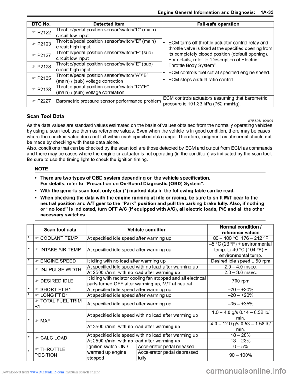
Scan Tool DataS7RS0B1104007
As the data values are standard values estimated on the basis of values obtained from the normally operating vehicles
by using a scan tool, use them as re ference values. Even when the vehicle is in good condition, there may be cases
where the checked value does not fall within each specified data range. Therefore, judgment as abnormal should not
be made by checking with these data alone.
Also, conditions that can be checked by the scan tool are those detected by ECM and output from ECM as commands
and there may be cases where the engine or actuator is not operating (in the condition) as indicated by the scan tool.
Be sure to use the timing light to check the ignition timing.
NOTE
• There are two types of OBD system depending on the vehicle specification.
For details, refer to “Precaution on On-Board Diagnostic (OBD) System”.
• With the generic scan tool, only star (*) marked data in the following table can be read.
• When checking the data with the engine running at idle or racing, be sure to shift M/T gear to the neutral position and A/T gear to the “Park” position and pull the parking brake fully. Also, if nothing
or “no load” is indicated, turn O FF A/C (if equipped with A/C), all electric loads, P/S and all the other
necessary switches.
�) P2122 Throttle/pedal position sensor/switch/“D” (main)
circuit low input
• ECM turns off throttle actuator control relay and throttle valve is fixed at the specified opening from
its completely closed position (default opening).
For details, refer to “Description of Electric
Throttle Body System”.
• ECM controls fuel cut at specified engine speed.
• ECM stops air/fuel ratio control.
�)
P2123 Throttle/pedal position sensor/switch/“D” (main)
circuit high input
�) P2127 Throttle/pedal position sensor/switch/“E” (sub)
circuit low input
�) P2128 Throttle/pedal position sensor/switch/“E” (sub)
circuit high input
�) P2135 Throttle/pedal position sensor/switch/“A”/“B”
(main) / (sub) voltage correction
�) P2138 Throttle pedal position sensor/switch “D”/“E”
(main) / (sub) voltage correlation
�) P2227 Barometric pressure sensor performance problem ECM controls actuators assuming that barometric
pressure is 101.33 kPa (762 mmHg).
DTC No. Detected item Fail-safe operation
Scan tool data
Vehicle condition Normal condition /
reference values
* �) COOLANT TEMP At specified idle speed after warming up 80 – 100 °C, 176 – 212 °F
* �) INTAKE AIR TEMP. At specifie d idle speed after warming up –5
°C (23 °F) + environmental
temp. to 40 °C (104 °F) +
environmental temp.
* �) ENGINE SPEED It idling with no load after warming upDesired idle speed ± 50 rpm
�) INJ PULSE WIDTH At specified idle speed with no load after warming up
2.0 – 4.0 msec.
At 2500 r/min. with no load after warming up 2.0 – 3.6 msec.
�) DESIRED IDLE It idling with radiator cooling fan stopped and all electrical
parts turned OFF after warming up, M/T at neutral 700 rpm
* �) SHORT FT B1 At specified idle speed after warming up –20 – +20%
* �) LONG FT B1 At specified idle speed after warming up –20 – +20%
�) TOTAL FUEL TRIM
B1 At specified idle speed after warming up
–35 – +35%
* �) MAF At specified idle speed wit
h no load after warming up 1.0 – 4.0 g/s 0.14 – 0.52 lb/
min.
At 2500 r/min. with no load after warming up 4.0 – 12.0 g/s 0.53 – 1.58 lb/
min.
* �) CALC LOAD At specified idle speed with no load after warming up
18 – 28%
At 2500 r/min. with no load after warming up 13 – 23%
* �)
THROTTLE
POSITION Ignition switch ON /
warmed up engine
stoppedAccelerator pedal released
0 – 5%
Accelerator pedal depressed
fully 90 – 100%
Page 85 of 1496
Downloaded from www.Manualslib.com manuals search engine Engine General Information and Diagnosis: 1A-35
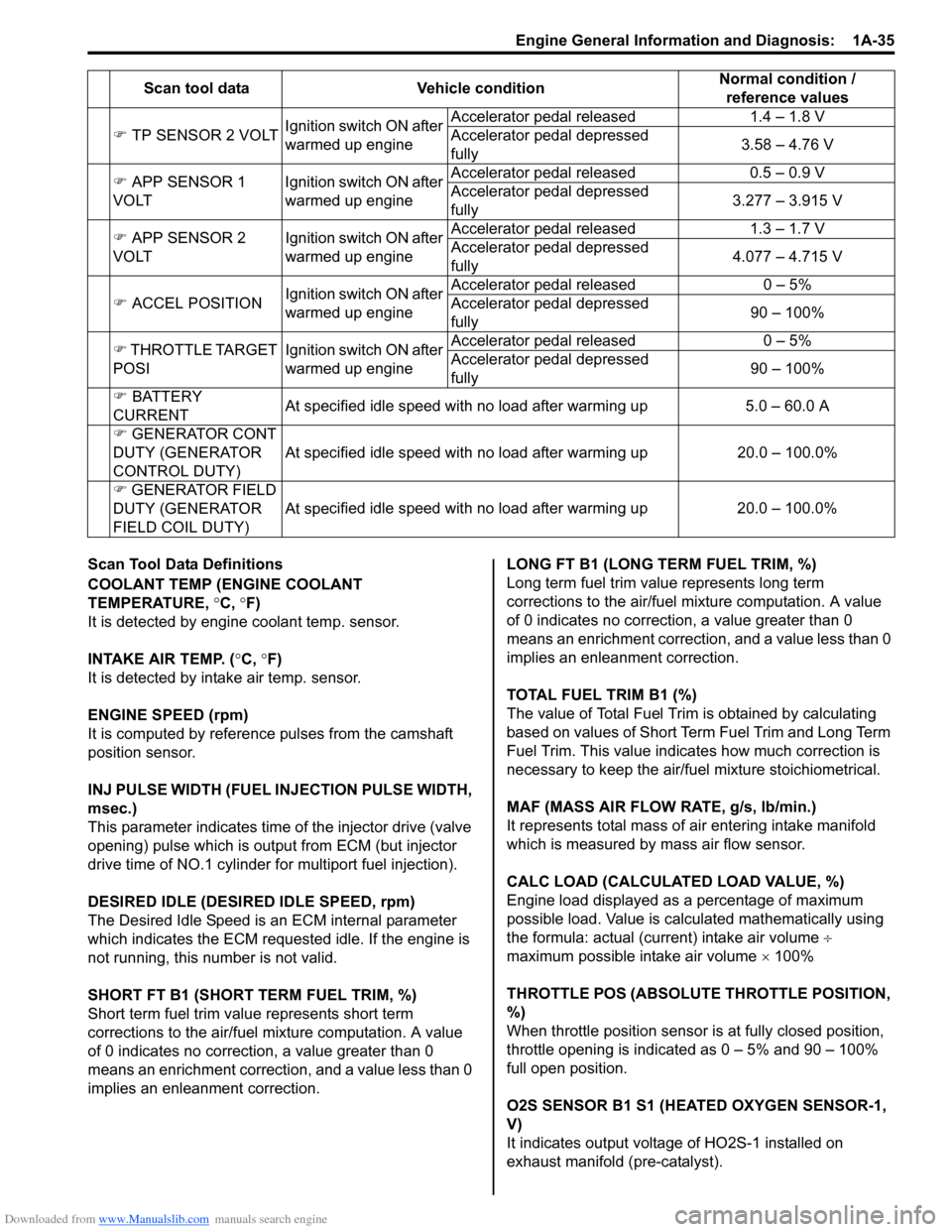
Scan Tool Data Definitions
COOLANT TEMP (ENGINE COOLANT
TEMPERATURE, °C, °F)
It is detected by engine coolant temp. sensor.
INTAKE AIR TEMP. ( °C, °F)
It is detected by intake air temp. sensor.
ENGINE SPEED (rpm)
It is computed by reference pulses from the camshaft
position sensor.
INJ PULSE WIDTH (FUEL INJECTION PULSE WIDTH,
msec.)
This parameter indicates time of the injector drive (valve
opening) pulse which is output from ECM (but injector
drive time of NO.1 cylinder fo r multiport fuel injection).
DESIRED IDLE (DESIRED IDLE SPEED, rpm)
The Desired Idle Speed is an ECM internal parameter
which indicates the ECM requested idle. If the engine is
not running, this number is not valid.
SHORT FT B1 (SHORT TERM FUEL TRIM, %)
Short term fuel trim valu e represents short term
corrections to the air/fuel mixture computation. A value
of 0 indicates no correction, a value greater than 0
means an enrichment correction, and a value less than 0
implies an enleanment correction. LONG FT B1 (LONG TERM FUEL TRIM, %)
Long term fuel trim value represents long term
corrections to the air/fuel mixture computation. A value
of 0 indicates no correction, a value greater than 0
means an enrichment correction, and a value less than 0
implies an enleanment correction.
TOTAL FUEL TRIM B1 (%)
The value of Total Fuel Trim is obtained by calculating
based on values of Short Term Fuel Trim and Long Term
Fuel Trim. This value indica
tes how much correction is
necessary to keep the air/fuel mixture stoichiometrical.
MAF (MASS AIR FLOW RATE, g/s, lb/min.)
It represents total mass of air entering intake manifold
which is measured by mass air flow sensor.
CALC LOAD (CALCULATED LOAD VALUE, %)
Engine load displayed as a percentage of maximum
possible load. Value is calculated mathematically using
the formula: actual (current) intake air volume ÷
maximum possible intake air volume × 100%
THROTTLE POS (ABSOLUTE THROTTLE POSITION,
%)
When throttle position sensor is at fully closed position,
throttle opening is indicated as 0 – 5% and 90 – 100%
full open position.
O2S SENSOR B1 S1 (HEA TED OXYGEN SENSOR-1,
V)
It indicates output voltage of HO2S-1 installed on
exhaust manifold (pre-catalyst).
�)
TP SENSOR 2 VOLT Ignition switch ON after
warmed up engine Accelerator pedal released
1.4 – 1.8 V
Accelerator pedal depressed
fully 3.58 – 4.76 V
�) APP SENSOR 1
VOLT Ignition switch ON after
warmed up engineAccelerator pedal released
0.5 – 0.9 V
Accelerator pedal depressed
fully 3.277 – 3.915 V
�) APP SENSOR 2
VOLT Ignition switch ON after
warmed up engineAccelerator pedal released
1.3 – 1.7 V
Accelerator pedal depressed
fully 4.077 – 4.715 V
�) ACCEL POSITION Ignition switch ON after
warmed up engine Accelerator pedal released
0 – 5%
Accelerator pedal depressed
fully 90 – 100%
�) THROTTLE TARGET
POSI Ignition switch ON after
warmed up engineAccelerator pedal released
0 – 5%
Accelerator pedal depressed
fully 90 – 100%
�) BATTERY
CURRENT At specified idle speed with no load after warming up
5.0 – 60.0 A
�) GENERATOR CONT
DUTY (GENERATOR
CONTROL DUTY) At specified idle speed with no load after warming up
20.0 – 100.0%
�) GENERATOR FIELD
DUTY (GENERATOR
FIELD COIL DUTY) At spe
cified idle speed with no load after warming up
20.0 – 100.0%
Scan tool data
Vehicle condition Normal condition /
reference values
Page 86 of 1496
Downloaded from www.Manualslib.com manuals search engine 1A-36 Engine General Information and Diagnosis:
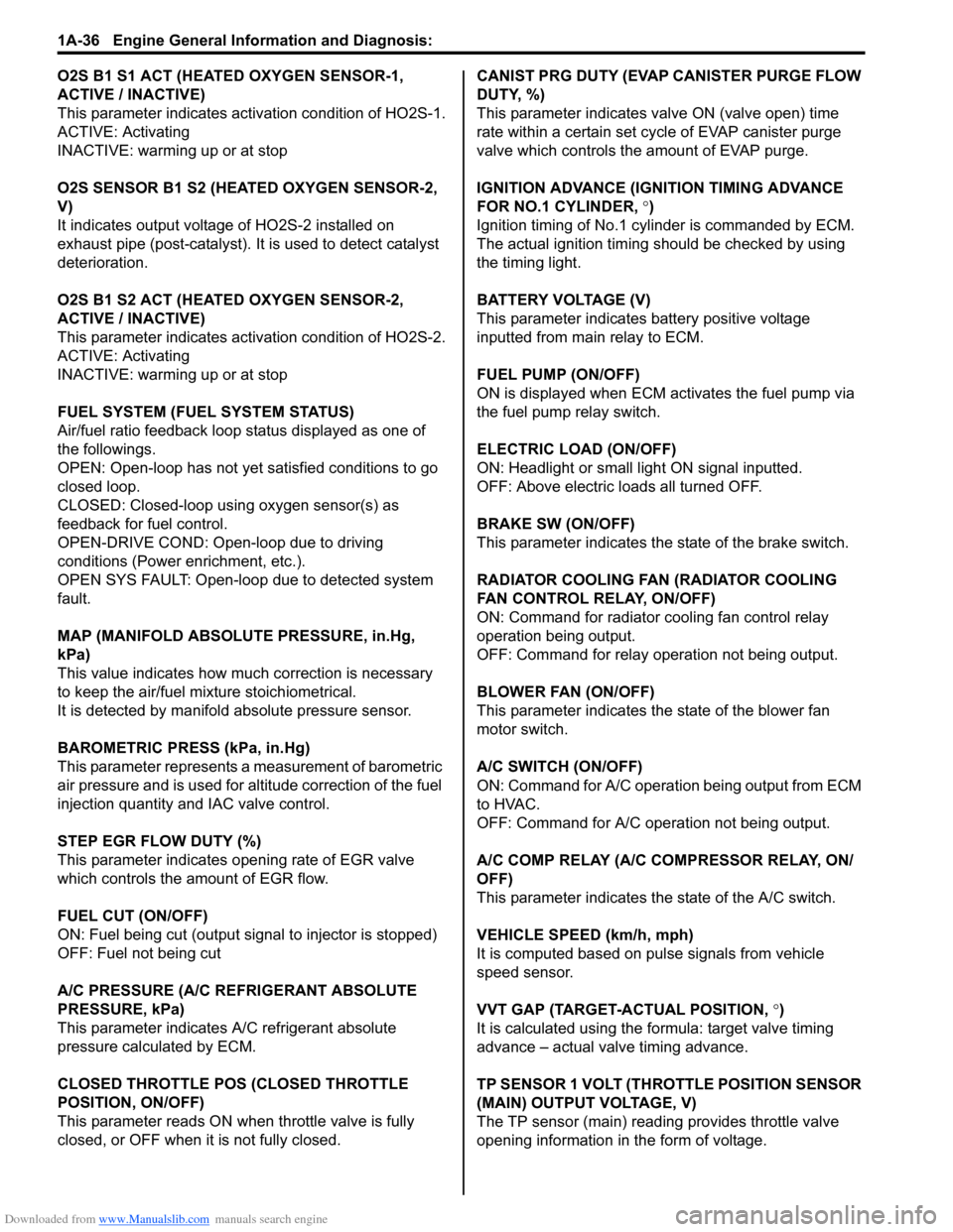
O2S B1 S1 ACT (HEATED OXYGEN SENSOR-1,
ACTIVE / INACTIVE)
This parameter indicates activation condition of HO2S-1.
ACTIVE: Activating
INACTIVE: warming up or at stop
O2S SENSOR B1 S2 (HEATED OXYGEN SENSOR-2,
V)
It indicates output voltage of HO2S-2 installed on
exhaust pipe (post-catalyst). It is used to detect catalyst
deterioration.
O2S B1 S2 ACT (HEATED OXYGEN SENSOR-2,
ACTIVE / INACTIVE)
This parameter indicates acti vation condition of HO2S-2.
ACTIVE: Activating
INACTIVE: warming up or at stop
FUEL SYSTEM (FUEL SYSTEM STATUS)
Air/fuel ratio feedback loop status displayed as one of
the followings.
OPEN: Open-loop has not yet satisfied conditions to go
closed loop.
CLOSED: Closed-loop using oxygen sensor(s) as
feedback for fuel control.
OPEN-DRIVE COND: Open-loop due to driving
conditions (Power enrichment, etc.).
OPEN SYS FAULT: Open-loop due to detected system
fault.
MAP (MANIFOLD ABSOLUTE PRESSURE, in.Hg,
kPa)
This value indicates how much correction is necessary
to keep the air/fuel mixture stoichiometrical.
It is detected by manifold absolute pressure sensor.
BAROMETRIC PRESS (kPa, in.Hg)
This parameter represents a measurement of barometric
air pressure and is used for al titude correction of the fuel
injection quantity and IAC valve control.
STEP EGR FLOW DUTY (%)
This parameter indicates opening rate of EGR valve
which controls the amount of EGR flow.
FUEL CUT (ON/OFF)
ON: Fuel being cut (output signal to injector is stopped)
OFF: Fuel not being cut
A/C PRESSURE (A/C REFRIGERANT ABSOLUTE
PRESSURE, kPa)
This parameter indicates A/C refrigerant absolute
pressure calculated by ECM.
CLOSED THROTTLE PO S (CLOSED THROTTLE
POSITION, ON/OFF)
This parameter reads ON wh en throttle valve is fully
closed, or OFF when it is not fully closed. CANIST PRG DUTY (EVAP CANISTER PURGE FLOW
DUTY, %)
This parameter indicates valve ON (valve open) time
rate within a certain set cycle of EVAP canister purge
valve which controls the amount of EVAP purge.
IGNITION ADVANCE (IGNITION TIMING ADVANCE
FOR NO.1 CYLINDER,
°)
Ignition timing of No.1 cylinder is commanded by ECM.
The actual ignition timing should be checked by using
the timing light.
BATTERY VOLTAGE (V)
This parameter indicates battery positive voltage
inputted from main relay to ECM.
FUEL PUMP (ON/OFF)
ON is displayed when ECM activates the fuel pump via
the fuel pump relay switch.
ELECTRIC LOAD (ON/OFF)
ON: Headlight or small light ON signal inputted.
OFF: Above electric loads all turned OFF.
BRAKE SW (ON/OFF)
This parameter indicates the state of the brake switch.
RADIATOR COOLING FAN (RADIATOR COOLING
FAN CONTROL RELAY, ON/OFF)
ON: Command for radiator cooling fan control relay
operation being output.
OFF: Command for relay operation not being output.
BLOWER FAN (ON/OFF)
This parameter indicates the state of the blower fan
motor switch.
A/C SWITCH (ON/OFF)
ON: Command for A/C operatio n being output from ECM
to HVAC.
OFF: Command for A/C oper ation not being output.
A/C COMP RELAY (A/C COMPRESSOR RELAY, ON/
OFF)
This parameter indicates the state of the A/C switch.
VEHICLE SPEED (km/h, mph)
It is computed based on pulse signals from vehicle
speed sensor.
VVT GAP (TARGET-ACTUAL POSITION, °)
It is calculated using the formula: target valve timing
advance – actual valve timing advance.
TP SENSOR 1 VOLT (THROTTLE POSITION SENSOR
(MAIN) OUTPUT VOLTAGE, V)
The TP sensor (main) reading provides throttle valve
opening information in the form of voltage.
Page 91 of 1496
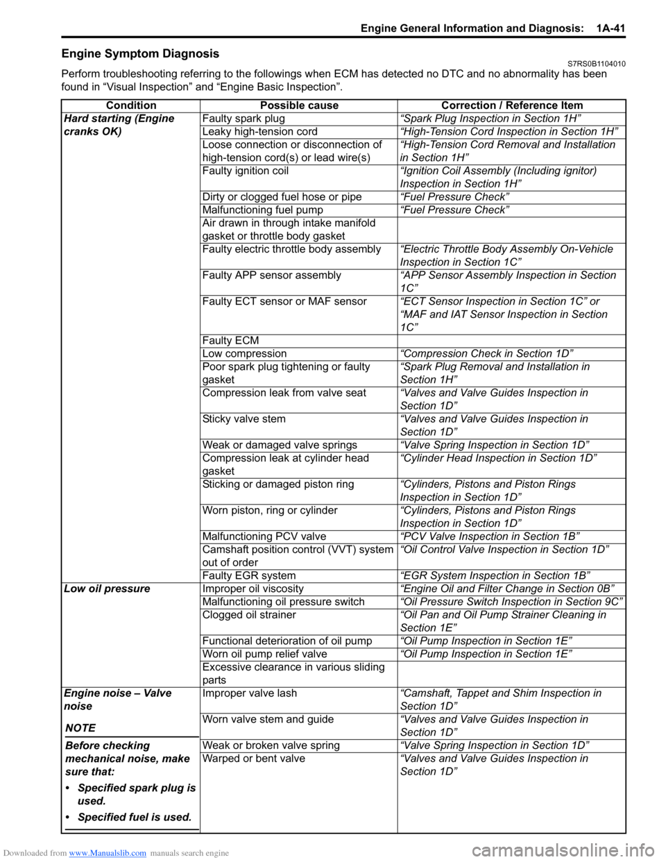
Downloaded from www.Manualslib.com manuals search engine Engine General Information and Diagnosis: 1A-41
Engine Symptom DiagnosisS7RS0B1104010
Perform troubleshooting referring to the followings when ECM has detected no DTC and no abnormality has been
found in “Visual Inspection” and “Engine Basic Inspection”.
Condition Possible cause Correction / Reference Item
Hard starting (Engine
cranks OK) Faulty spark plug
“Spark Plug Inspection in Section 1H”
Leaky high-tension cord “High-Tension Cord Inspection in Section 1H”
Loose connection or disconnection of
high-tension cord(s) or lead wire(s) “High-Tension Cord Removal and Installation
in Section 1H”
Faulty ignition coil “Ignition Coil Assembly (Including ignitor)
Inspection in Section 1H”
Dirty or clogged fuel hose or pipe “Fuel Pressure Check”
Malfunctioning fuel pump “Fuel Pressure Check”
Air drawn in through intake manifold
gasket or throttle body gasket
Faulty electric throttle body assembly “Electric Throttle Body Assembly On-Vehicle
Inspection in Section 1C”
Faulty APP sensor assembly “APP Sensor Assembly Inspection in Section
1C”
Faulty ECT sensor or MAF sensor “ECT Sensor Inspection in Section 1C” or
“MAF and IAT Sensor Inspection in Section
1C”
Faulty ECM
Low compression “Compression Check in Section 1D”
Poor spark plug tightening or faulty
gasket “Spark Plug Removal and Installation in
Section 1H”
Compression leak from valve seat “Valves and Valve Guides Inspection in
Section 1D”
Sticky valve stem “Valves and Valve Guides Inspection in
Section 1D”
Weak or damaged valve springs “Valve Spring Inspection in Section 1D”
Compression leak at cylinder head
gasket “Cylinder Head Inspection in Section 1D”
Sticking or damaged piston ring “Cylinders, Pistons and Piston Rings
Inspection in Section 1D”
Worn piston, ring or cylinder “Cylinders, Pistons and Piston Rings
Inspection in Section 1D”
Malfunctioning PCV valve “PCV Valve Inspection in Section 1B”
Camshaft position control (VVT) system
out of order “Oil Control Valve Inspection in Section 1D”
Faulty EGR system “EGR System Inspection in Section 1B”
Low oil pressure Improper oil viscosity “Engine Oil and Filter Change in Section 0B”
Malfunctioning oil pressure switch “Oil Pressure Switch Inspection in Section 9C”
Clogged oil strainer “Oil Pan and Oil Pump Strainer Cleaning in
Section 1E”
Functional deterioration of oil pump “Oil Pump Inspection in Section 1E”
Worn oil pump relief valve “Oil Pump Inspection in Section 1E”
Excessive clearance in various sliding
parts
Engine noise – Valve
noise
NOTE
Before checking
mechanical noise, make
sure that:
• Specified spark plug is used.
• Specified fuel is used.
Improper valve lash “Camshaft, Tappet and Shim Inspection in
Section 1D”
Worn valve stem and guide “Valves and Valve Guides Inspection in
Section 1D”
Weak or broken valve spring “Valve Spring Inspection in Section 1D”
Warped or bent valve “Valves and Valve Guides Inspection in
Section 1D”
Page 92 of 1496
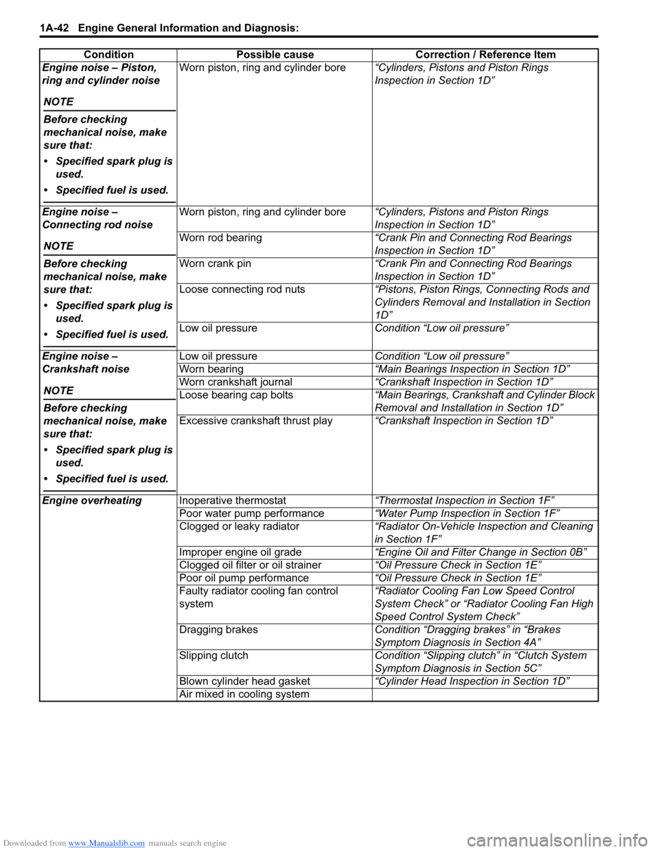
Downloaded from www.Manualslib.com manuals search engine 1A-42 Engine General Information and Diagnosis:
Engine noise – Piston,
ring and cylinder noise
NOTE
Before checking
mechanical noise, make
sure that:
• Specified spark plug is used.
• Specified fuel is used.
Worn piston, ring and cylinder bore “Cylinders, Pistons and Piston Rings
Inspection in Section 1D”
Engine noise –
Connecting rod noise
NOTE
Before checking
mechanical noise, make
sure that:
• Specified spark plug is used.
• Specified fuel is used.
Worn piston, ring and cylinder bore “Cylinders, Pistons and Piston Rings
Inspection in Section 1D”
Worn rod bearing “Crank Pin and Connecting Rod Bearings
Inspection in Section 1D”
Worn crank pin “Crank Pin and Connecting Rod Bearings
Inspection in Section 1D”
Loose connecting rod nuts “Pistons, Piston Rings, Connecting Rods and
Cylinders Removal and Installation in Section
1D”
Low oil pressure Condition “Low oil pressure”
Engine noise –
Crankshaft noise
NOTE
Before checking
mechanical noise, make
sure that:
• Specified spark plug is used.
• Specified fuel is used.
Low oil pressure Condition “Low oil pressure”
Worn bearing “Main Bearings Inspection in Section 1D”
Worn crankshaft journal “Crankshaft Inspection in Section 1D”
Loose bearing cap bolts “Main Bearings, Crankshaft and Cylinder Block
Removal and Installation in Section 1D”
Excessive crankshaft thrust play “Crankshaft Inspection in Section 1D”
Engine overheating Inoperative thermostat “Thermostat Inspection in Section 1F”
Poor water pump performance “Water Pump Inspection in Section 1F”
Clogged or leaky radiator “Radiator On-Vehicle Inspection and Cleaning
in Section 1F”
Improper engine oil grade “Engine Oil and Filter Change in Section 0B”
Clogged oil filter or oil strainer “Oil Pressure Check in Section 1E”
Poor oil pump performance “Oil Pressure Check in Section 1E”
Faulty radiator cooling fan control
system “Radiator Cooling Fan Low Speed Control
System Check” or “Rad
iator Cooling Fan High
Speed Control System Check”
Dragging brakes Condition “Dragging brakes” in “Brakes
Symptom Diagnosis in Section 4A”
Slipping clutch Condition “Slipping clutch” in “Clutch System
Symptom Diagnosis in Section 5C”
Blown cylinder head gasket “Cylinder Head Inspection in Section 1D”
Air mixed in cooling system
Condition Possible cause Correction / Reference Item