throttle body system SUZUKI SWIFT 2005 2.G Service Owner's Manual
[x] Cancel search | Manufacturer: SUZUKI, Model Year: 2005, Model line: SWIFT, Model: SUZUKI SWIFT 2005 2.GPages: 1496, PDF Size: 34.44 MB
Page 96 of 1496
Downloaded from www.Manualslib.com manuals search engine 1A-46 Engine General Information and Diagnosis:
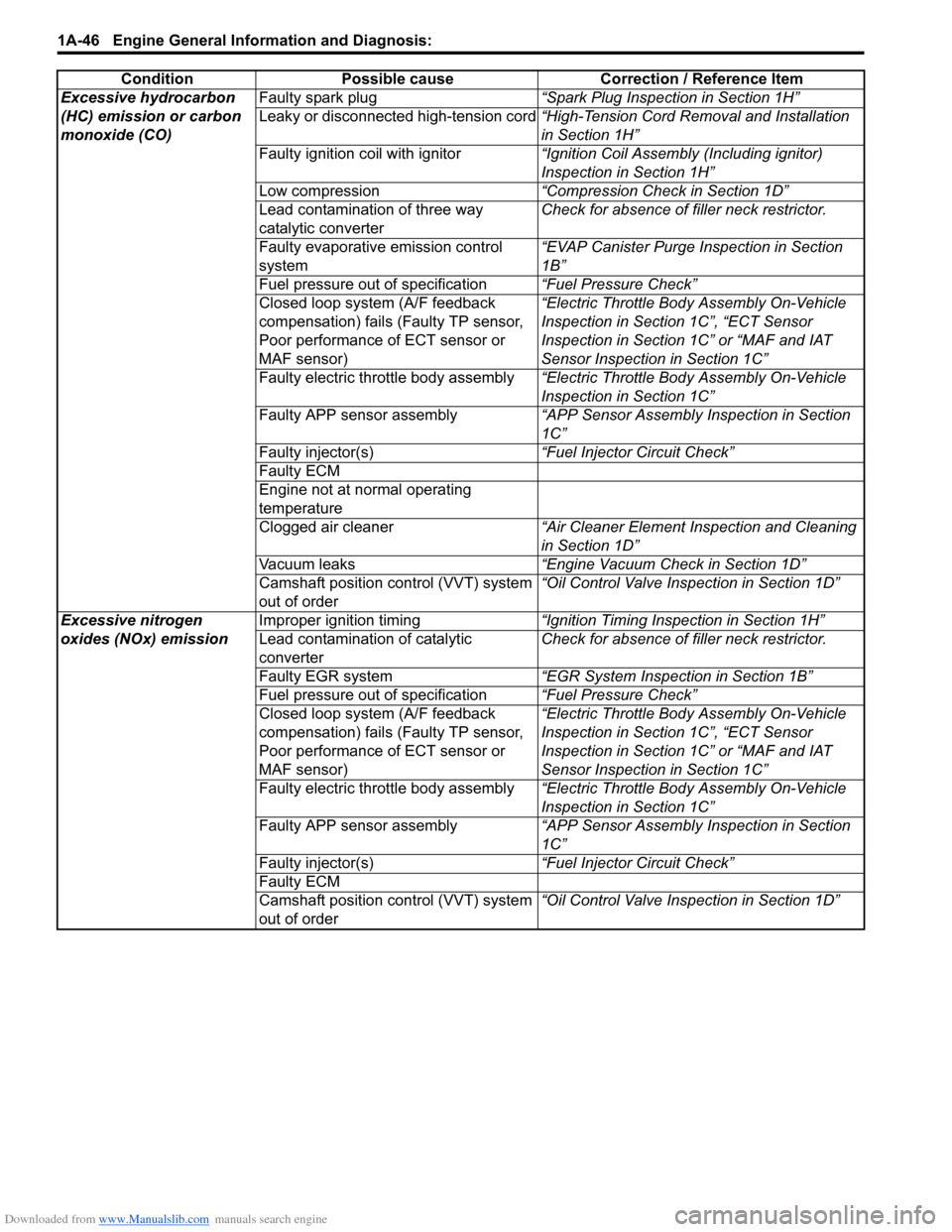
Excessive hydrocarbon
(HC) emission or carbon
monoxide (CO)Faulty spark plug
“Spark Plug Inspection in Section 1H”
Leaky or disconnected high-tension cord “High-Tension Cord Removal and Installation
in Section 1H”
Faulty ignition coil with ignitor “Ignition Coil Assembly (Including ignitor)
Inspection in Section 1H”
Low compression “Compression Check in Section 1D”
Lead contamination of three way
catalytic converter Check for absence of f
iller neck restrictor.
Faulty evaporative emission control
system “EVAP Canister Purge Inspection in Section
1B”
Fuel pressure out of specification “Fuel Pressure Check”
Closed loop system (A/F feedback
compensation) fails (Faulty TP sensor,
Poor performance of ECT sensor or
MAF sensor) “Electric Throttle Body Assembly On-Vehicle
Inspection in Section 1C”, “ECT Sensor
Inspection in Section 1C” or “MAF and IAT
Sensor Inspection in Section 1C”
Faulty electric throttle body assembly “Electric Throttle Body Assembly On-Vehicle
Inspection in Section 1C”
Faulty APP sensor assembly “APP Sensor Assembly Inspection in Section
1C”
Faulty injector(s) “Fuel Injector Circuit Check”
Faulty ECM
Engine not at normal operating
temperature
Clogged air cleaner “Air Cleaner Element Inspection and Cleaning
in Section 1D”
Vacuum leaks “Engine Vacuum Check in Section 1D”
Camshaft position control (VVT) system
out of order “Oil Control Valve Inspection in Section 1D”
Excessive nitrogen
oxides (NOx) emission Improper ignition timing
“Ignition Timing Inspection in Section 1H”
Lead contamination of catalytic
converter Check for absence of f
iller neck restrictor.
Faulty EGR system “EGR System Inspection in Section 1B”
Fuel pressure out of specification “Fuel Pressure Check”
Closed loop system (A/F feedback
compensation) fails (Faulty TP sensor,
Poor performance of ECT sensor or
MAF sensor) “Electric Throttle Body Assembly On-Vehicle
Inspection in Section 1C”, “ECT Sensor
Inspection in Section 1C” or “MAF and IAT
Sensor Inspection in Section 1C”
Faulty electric throttle body assembly “Electric Throttle Body Assembly On-Vehicle
Inspection in Section 1C”
Faulty APP sensor assembly “APP Sensor Assembly Inspection in Section
1C”
Faulty injector(s) “Fuel Injector Circuit Check”
Faulty ECM
Camshaft position control (VVT) system
out of order “Oil Control Valve Inspection in Section 1D”
Condition Possible cause Correction / Reference Item
Page 134 of 1496
Downloaded from www.Manualslib.com manuals search engine 1A-84 Engine General Information and Diagnosis:
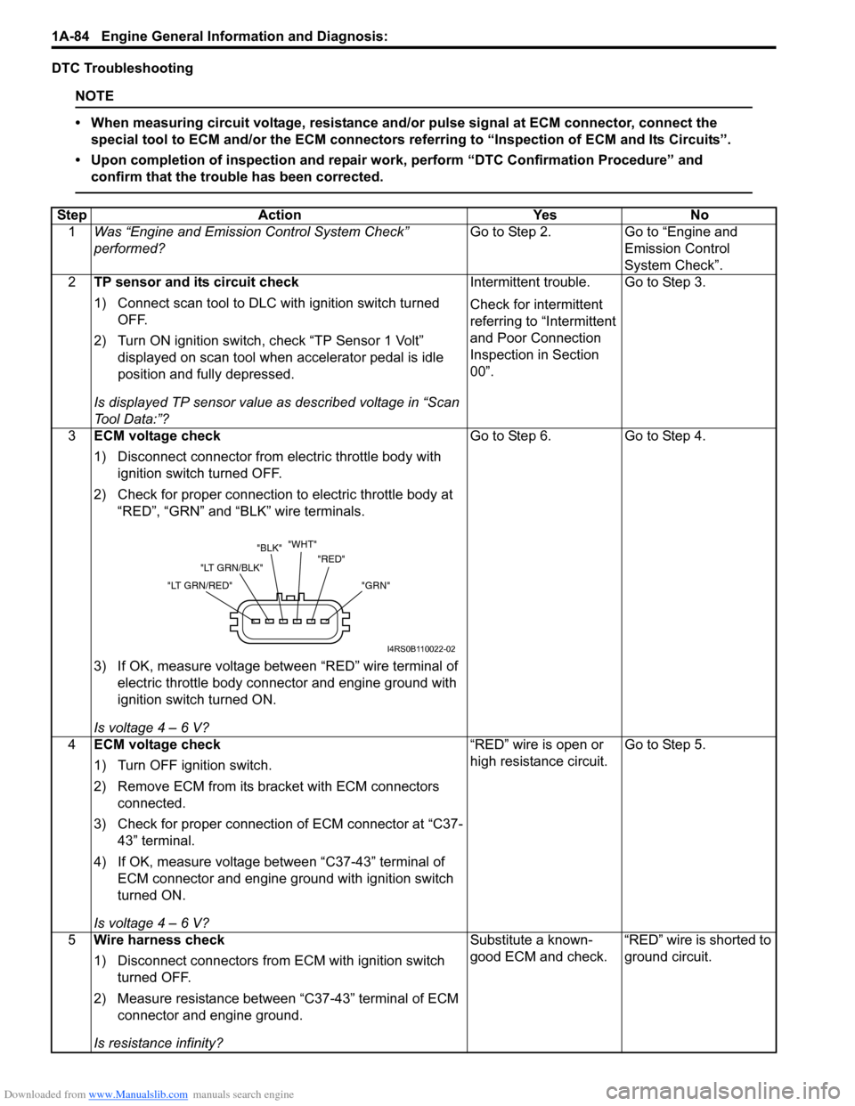
DTC Troubleshooting
NOTE
• When measuring circuit voltage, resistance and/or pulse signal at ECM connector, connect the
special tool to ECM and/or the ECM connectors re ferring to “Inspection of ECM and Its Circuits”.
• Upon completion of inspection and repair work, perform “DTC Confirmation Procedure” and confirm that the trouble has been corrected.
Step Action YesNo
1 Was “Engine and Emission Control System Check”
performed? Go to Step 2.
Go to “Engine and
Emission Control
System Check”.
2 TP sensor and its circuit check
1) Connect scan tool to DLC with ignition switch turned
OFF.
2) Turn ON ignition switch, check “TP Sensor 1 Volt” displayed on scan tool when accelerator pedal is idle
position and fully depressed.
Is displayed TP sensor value as described voltage in “Scan
Tool Data:”? Intermittent trouble.
Check for intermittent
referring to “Intermittent
and Poor Connection
Inspection in Section
00”.
Go to Step 3.
3 ECM voltage check
1) Disconnect connector from electric throttle body with
ignition switch turned OFF.
2) Check for proper connection to electric throttle body at “RED”, “GRN” and “BLK” wire terminals.
3) If OK, measure voltage between “RED” wire terminal of electric throttle body connector and engine ground with
ignition switch turned ON.
Is voltage 4 – 6 V? Go to Step 6.
Go to Step 4.
4 ECM voltage check
1) Turn OFF ignition switch.
2) Remove ECM from its br acket with ECM connectors
connected.
3) Check for proper connection of ECM connector at “C37- 43” terminal.
4) If OK, measure voltage between “C37-43” terminal of ECM connector and engine ground with ignition switch
turned ON.
Is voltage 4 – 6 V? “RED” wire is open or
high resistance circuit.
Go to Step 5.
5 Wire harness check
1) Disconnect connectors from ECM with ignition switch
turned OFF.
2) Measure resistance between “C37-43” terminal of ECM connector and engine ground.
Is resistance infinity? Substitute a known-
good ECM and check.
“RED” wire is shorted to
ground circuit.
"GRN"
"RED"
"WHT"
"BLK"
"LT GRN/BLK"
"LT GRN/RED"
I4RS0B110022-02
Page 136 of 1496
Downloaded from www.Manualslib.com manuals search engine 1A-86 Engine General Information and Diagnosis:
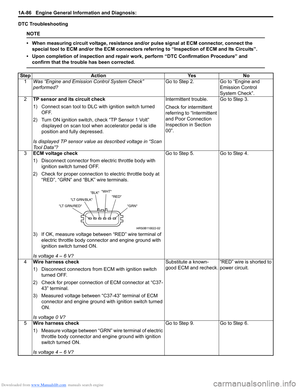
DTC Troubleshooting
NOTE
• When measuring circuit voltage, resistance and/or pulse signal at ECM connector, connect the
special tool to ECM and/or the ECM connectors re ferring to “Inspection of ECM and Its Circuits”.
• Upon completion of inspection and repair work, perform “DTC Confirmation Procedure” and confirm that the trouble has been corrected.
Step Action YesNo
1 Was “Engine and Emission Control System Check”
performed? Go to Step 2.
Go to “Engine and
Emission Control
System Check”.
2 TP sensor and its circuit check
1) Connect scan tool to DLC with ignition switch turned
OFF.
2) Turn ON ignition switch, check “TP Sensor 1 Volt” displayed on scan tool when accelerator pedal is idle
position and fully depressed.
Is displayed TP sensor value as described voltage in “Scan
To o l D a t a ” ? Intermittent trouble.
Check for intermittent
referring to “Intermittent
and Poor Connection
Inspection in Section
00”.
Go to Step 3.
3 ECM voltage check
1) Disconnect connector from electric throttle body with
ignition switch turned OFF.
2) Check for proper connection to electric throttle body at “RED”, “GRN” and “BLK” wire terminals.
3) If OK, measure voltage between “RED” wire terminal of electric throttle body connector and engine ground with
ignition switch turned ON.
Is voltage 4 – 6 V? Go to Step 5.
Go to Step 4.
4 Wire harness check
1) Disconnect connectors from ECM with ignition switch
turned OFF.
2) Check for proper connection of ECM connector at “C37- 43” terminal.
3) Measured voltage between “C37-43” terminal of ECM connector and engine ground with ignition switch turned
ON.
Is voltage 0 V? Substitute a known-
good ECM and recheck.
“RED” wire is shorted to
power circuit.
5 Wire harness check
1) Measure voltage between “GRN” wire terminal of electric
throttle body connector and engine ground with ignition
switch turned ON.
Is voltage 4 – 6 V? Go to Step 9.
Go to Step 6.
"GRN"
"RED"
"WHT"
"BLK"
"LT GRN/BLK"
"LT GRN/RED"
I4RS0B110022-02
Page 151 of 1496
Downloaded from www.Manualslib.com manuals search engine Engine General Information and Diagnosis: 1A-101
NOTE
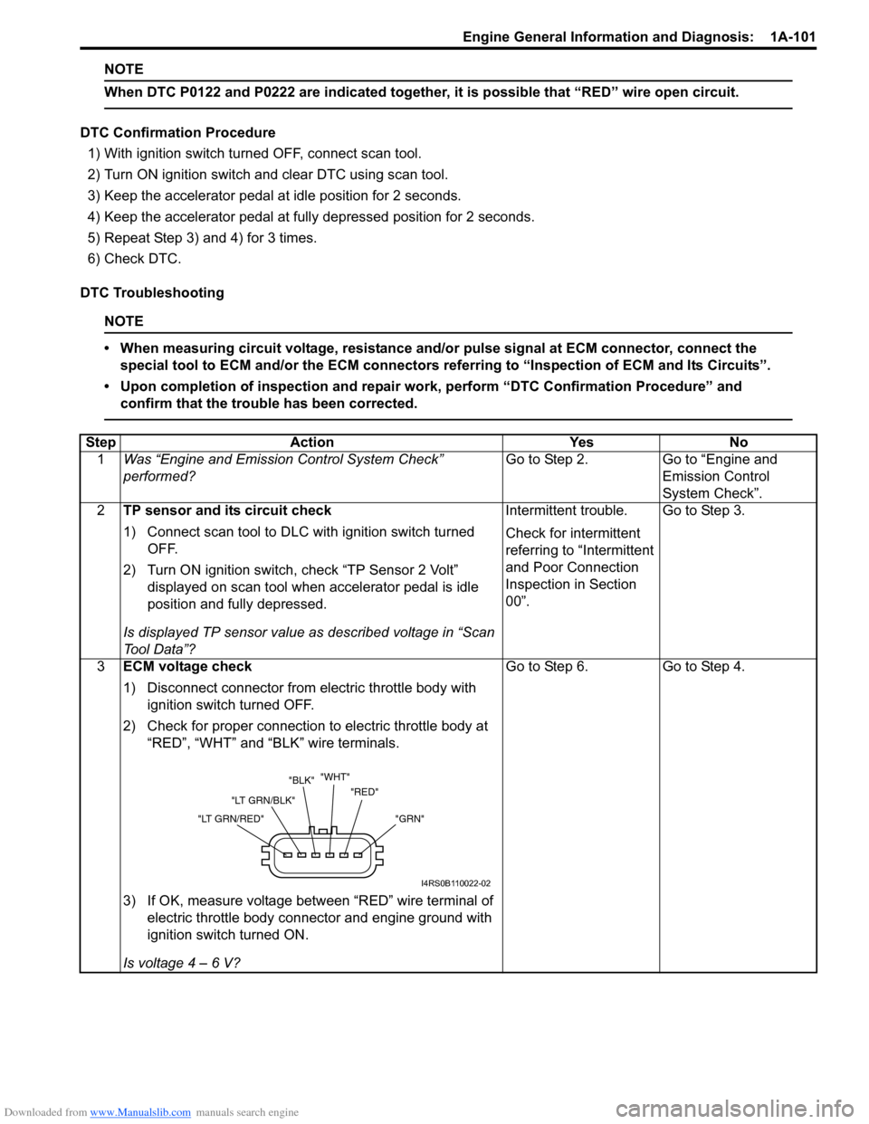
When DTC P0122 and P0222 are indicated together, it is possible that “RED” wire open circuit.
DTC Confirmation Procedure
1) With ignition switch turned OFF, connect scan tool.
2) Turn ON ignition switch and clear DTC using scan tool.
3) Keep the accelerator pedal at idle position for 2 seconds.
4) Keep the accelerator pedal at fully depressed position for 2 seconds.
5) Repeat Step 3) and 4) for 3 times.
6) Check DTC.
DTC Troubleshooting
NOTE
• When measuring circuit voltage, resistance and/ or pulse signal at ECM connector, connect the
special tool to ECM and/or the ECM connectors re ferring to “Inspection of ECM and Its Circuits”.
• Upon completion of inspection and repair work, perform “DTC Confirmation Procedure” and confirm that the trouble has been corrected.
Step Action YesNo
1 Was “Engine and Emission Control System Check”
performed? Go to Step 2.
Go to “Engine and
Emission Control
System Check”.
2 TP sensor and its circuit check
1) Connect scan tool to DLC with ignition switch turned
OFF.
2) Turn ON ignition switch, check “TP Sensor 2 Volt” displayed on scan tool when accelerator pedal is idle
position and fully depressed.
Is displayed TP sensor value as described voltage in “Scan
To o l D a t a ” ? Intermittent trouble.
Check for intermittent
referring to “Intermittent
and Poor Connection
Inspection in Section
00”.
Go to Step 3.
3 ECM voltage check
1) Disconnect connector from electric throttle body with
ignition switch turned OFF.
2) Check for proper connection to electric throttle body at “RED”, “WHT” and “BLK” wire terminals.
3) If OK, measure voltage between “RED” wire terminal of electric throttle body connector and engine ground with
ignition switch turned ON.
Is voltage 4 – 6 V? Go to Step 6.
Go to Step 4.
"GRN"
"RED"
"WHT"
"BLK"
"LT GRN/BLK"
"LT GRN/RED"
I4RS0B110022-02
Page 153 of 1496
Downloaded from www.Manualslib.com manuals search engine Engine General Information and Diagnosis: 1A-103
NOTE
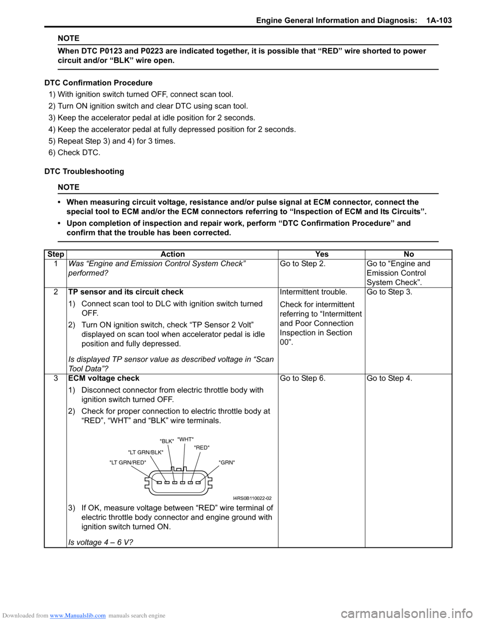
When DTC P0123 and P0223 are indicated together, it is possible that “RED” wire shorted to power
circuit and/or “BLK” wire open.
DTC Confirmation Procedure
1) With ignition switch turned OFF, connect scan tool.
2) Turn ON ignition switch and clear DTC using scan tool.
3) Keep the accelerator pedal at idle position for 2 seconds.
4) Keep the accelerator pedal at fully depressed position for 2 seconds.
5) Repeat Step 3) and 4) for 3 times.
6) Check DTC.
DTC Troubleshooting
NOTE
• When measuring circuit voltage, resistance and/ or pulse signal at ECM connector, connect the
special tool to ECM and/or the ECM connectors re ferring to “Inspection of ECM and Its Circuits”.
• Upon completion of inspection and repair work, perform “DTC Confirmation Procedure” and confirm that the trouble has been corrected.
Step Action YesNo
1 Was “Engine and Emission Control System Check”
performed? Go to Step 2.
Go to “Engine and
Emission Control
System Check”.
2 TP sensor and its circuit check
1) Connect scan tool to DLC with ignition switch turned
OFF.
2) Turn ON ignition switch, check “TP Sensor 2 Volt” displayed on scan tool when accelerator pedal is idle
position and fully depressed.
Is displayed TP sensor value as described voltage in “Scan
To o l D a t a ” ? Intermittent trouble.
Check for intermittent
referring to “Intermittent
and Poor Connection
Inspection in Section
00”.
Go to Step 3.
3 ECM voltage check
1) Disconnect connector from electric throttle body with
ignition switch turned OFF.
2) Check for proper connection to electric throttle body at “RED”, “WHT” and “BLK” wire terminals.
3) If OK, measure voltage between “RED” wire terminal of electric throttle body connector and engine ground with
ignition switch turned ON.
Is voltage 4 – 6 V? Go to Step 6.
Go to Step 4.
"GRN"
"RED"
"WHT"
"BLK"
"LT GRN/BLK"
"LT GRN/RED"
I4RS0B110022-02
Page 155 of 1496
Downloaded from www.Manualslib.com manuals search engine Engine General Information and Diagnosis: 1A-105
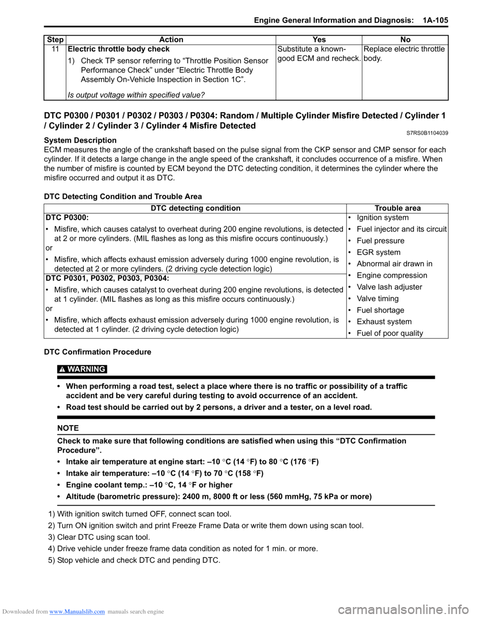
DTC P0300 / P0301 / P0302 / P0303 / P0304: Random / Multiple Cylinder Misfire Detected / Cylinder 1
/ Cylinder 2 / Cylinder 3 / Cylinder 4 Misfire Detected
S7RS0B1104039
System Description
ECM measures the angle of the crankshaft based on the pulse signal from the CKP sensor and CMP sensor for each
cylinder. If it detects a large change in the angle speed of the crankshaft, it concludes occurrence of a misfire. When
the number of misfire is counted by ECM beyond the DTC de tecting condition, it determines the cylinder where the
misfire occurred and output it as DTC.
DTC Detecting Condition and Trouble Area
DTC Confirmation Procedure
WARNING!
• When performing a road test, select a place where there is no traffic or possibility of a traffic accident and be very careful during testing to avoid occurrence of an accident.
• Road test should be carried out by 2 persons, a driver and a tester, on a level road.
NOTE
Check to make sure that following conditions ar e satisfied when using this “DTC Confirmation
Procedure”.
• Intake air temperature at engine start: –10 °C (14 ° F) to 80 °C (176 °F)
• Intake air temperature: –10 °C (14 °F) to 70 °C (158 °F)
• Engine coolant temp.: –10 °C, 14 °F or higher
• Altitude (barometric pressure): 2400 m, 8000 ft or less (560 mmHg, 75 kPa or more)
1) With ignition switch turned OFF, connect scan tool.
2) Turn ON ignition switch and print Freeze Frame Data or write them down using scan tool.
3) Clear DTC using scan tool.
4) Drive vehicle under freeze frame data condition as noted for 1 min. or more.
5) Stop vehicle and check DTC and pending DTC. 11
Electric throttle body check
1) Check TP sensor referring to “Throttle Position Sensor
Performance Check” under “Electric Throttle Body
Assembly On-Vehicle Inspection in Section 1C”.
Is output voltage within specified value? Substitute a known-
good ECM and recheck.
Replace electric throttle
body.
Step Action Yes No
DTC detecting condition
Trouble area
DTC P0300:
• Misfire, which causes catalyst to overheat during 200 engine revolutions, is detected at 2 or more cylinders. (MIL flashes as lo ng as this misfire occurs continuously.)
or
• Misfire, which affects exhaust emission adv ersely during 1000 engine revolution, is
detected at 2 or more cylinders. (2 driving cycle detection logic) • Ignition system
• Fuel injector and its circuit
• Fuel pressure
• EGR system
• Abnormal air drawn in
• Engine compression
• Valve lash adjuster
• Valve timing
• Fuel shortage
• Exhaust system
• Fuel of poor quality
DTC P0301, P0302, P0303, P0304:
• Misfire, which causes catalyst to overheat during 200 engine revolutions, is detected
at 1 cylinder. (MIL flashes as long as this misfire occurs continuously.)
or
• Misfire, which affects exhaust emission adv ersely during 1000 engine revolution, is
detected at 1 cylinder. (2 driving cycle detection logic)
Page 203 of 1496
Downloaded from www.Manualslib.com manuals search engine Engine General Information and Diagnosis: 1A-153
DTC Troubleshooting
NOTE
• When measuring circuit voltage, resistance and/or pulse signal at ECM connector, connect the
special tool to ECM and/or the ECM connectors re ferring to “Inspection of ECM and Its Circuits”.
• Upon completion of inspection and repair work, perform “DTC Confirmation Procedure” and confirm that the trouble has been corrected.
Step Action YesNo
1 Was “Engine and Emission Control System Check”
performed? Go to Step 2.
Go to “Engine and
Emission Control
System Check”.
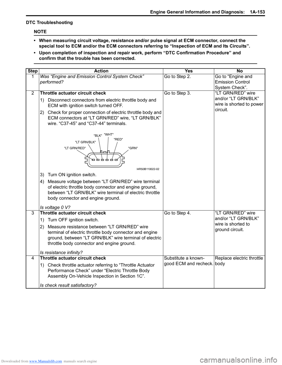
2 Throttle actuator circuit check
1) Disconnect connectors from electric throttle body and
ECM with ignition switch turned OFF.
2) Check for proper connection of electric throttle body and ECM connectors at “LT GRN/RED” wire, “LT GRN/BLK”
wire. “C37-45” and “C37-44” terminals.
3) Turn ON ignition switch.
4) Measure voltage between “LT GRN/RED” wire terminal of electric throttle body connector and engine ground,
between “LT GRN/BLK” wire terminal of electric throttle
body connector and engine ground.
Is voltage 0 V? Go to Step 3.
“LT GRN/RED” wire
and/or “LT GRN/BLK”
wire is shorted to power
circuit.
3 Throttle actuator circuit check
1) Turn OFF ignition switch.
2) Measure resistance between “LT GRN/RED” wire
terminal of electric throttle body connector and engine
ground, between “LT GRN/BLK” wire terminal of electric
throttle body connector and engine ground.
Is resistance infinity? Go to Step 4.
“LT GRN/RED” wire
and/or “LT GRN/BLK”
wire is shorted to
ground circuit.
4 Throttle actuator circuit check
1) Check throttle actuator refe rring to “Throttle Actuator
Performance Check” under “Electric Throttle Body
Assembly On-Vehicle Inspection in Section 1C”.
Is check result satisfactory? Substitute a known-
good ECM and recheck.
Replace electric throttle
body
"GRN"
"RED"
"WHT"
"BLK"
"LT GRN/BLK"
"LT GRN/RED"
I4RS0B110022-02
Page 206 of 1496
Downloaded from www.Manualslib.com manuals search engine 1A-156 Engine General Information and Diagnosis:
DTC Troubleshooting
NOTE
• When measuring circuit voltage, resistance and/or pulse signal at ECM connector, connect the
special tool to ECM and/or the ECM connectors re ferring to “Inspection of ECM and Its Circuits”.
• Upon completion of inspection and repair work, perform “DTC Confirmation Procedure” and confirm that the trouble has been corrected.
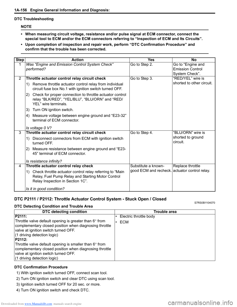
DTC P2111 / P2112: Throttle Actuator Control System - Stuck Open / ClosedS7RS0B1104070
DTC Detecting Condition and Trouble Area
DTC Confirmation Procedure
1) With ignition switch turned OFF, connect scan tool.
2) Turn ON ignition switch and clear DTC using scan tool.
3) Ignition switch turned OFF for 20 sec. or more.
4) Turn ON ignition switch and check DTC.
Step Action Yes No
1 Was “Engine and Emission Control System Check”
performed? Go to Step 2. Go to “Engine and
Emission Control
System Check”.
2 Throttle actuator cont rol relay circuit check
1) Remove throttle actuator co ntrol relay from individual
circuit fuse box No.1 with ignition switch turned OFF.
2) Check for proper connection to throttle actuator control relay “BLK/RED”, “YEL/BLU”, “BLU/ORN” and “RED/
YEL” wire terminals.
3) Turn ON ignition switch.
4) Measure voltage between engine ground and “E23-32” terminal of ECM connector.
Is voltage 0 V? Go to Step 3. “RED/YEL” wire is
shorted to other circuit.
3 Throttle actuator cont rol relay circuit check
1) Disconnect connectors from ECM with ignition switch turned OFF.
2) Measure resistance between engine ground and “E23- 45” terminal of ECM connector.
Is resistance infinity? Go to Step 4. “BLU/ORN” wire is
shorted to ground
circuit.
4 Throttle actuator control relay check
1) Check throttle actuator control relay referring to “Main Relay, Fuel Pump Relay an d Starting Motor Control
Relay Inspection in Section 1C”.
Is it in good condition? Substitute a known-
good ECM and recheck.
Replace throttle
actuator control relay.
DTC detecting condition
Trouble area
P2111:
Throttle valve default opening is greater than 6 ° from
complementary closed position when diagnosing throttle
valve at ignition switch turned OFF.
(1 driving detection logic)
P2112:
Throttle valve default opening is smaller than 6 ° from
complementary closed position when diagnosing throttle
valve at ignition switch turned OFF.
(1 driving detection logic) • Electric throttle body
•ECM
Page 207 of 1496
Downloaded from www.Manualslib.com manuals search engine Engine General Information and Diagnosis: 1A-157
DTC Troubleshooting
NOTE
• When measuring circuit voltage, resistance and/or pulse signal at ECM connector, connect the
special tool to ECM and/or the ECM connectors re ferring to “Inspection of ECM and Its Circuits”.
• Upon completion of inspection and repair work, perform “DTC Confirmation Procedure” and confirm that the trouble has been corrected.
DTC P2119: Throttle Actuator Control Throttle Body Range / PerformanceS7RS0B1104071
Wiring Diagram
Refer to “DTC P2101: Throttle Actuator Control Motor Circuit Range / Performance”.
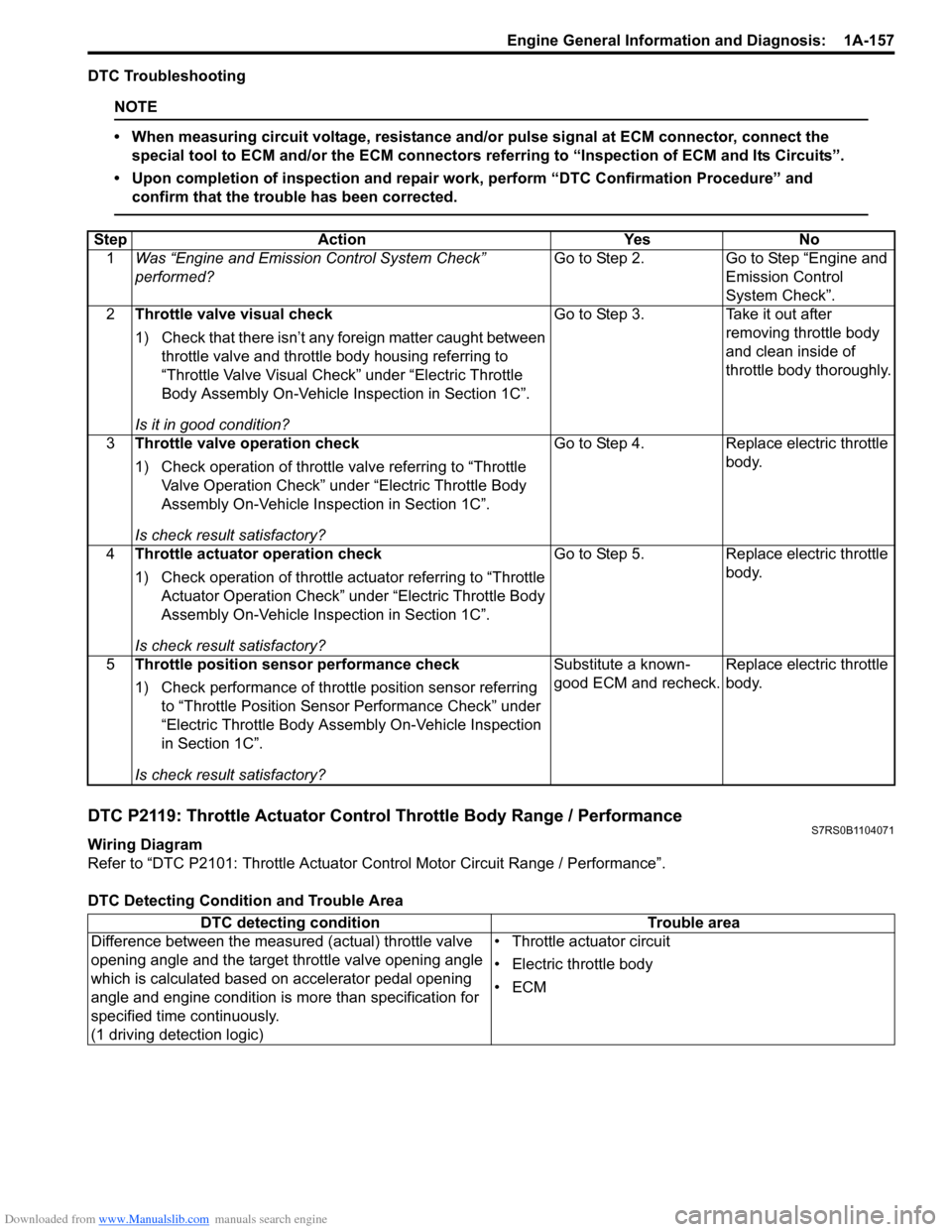
DTC Detecting Condition and Trouble Area Step Action Yes No
1 Was “Engine and Emission Control System Check”
performed? Go to Step 2. Go to Step “Engine and
Emission Control
System Check”.
2 Throttle valve visual check
1) Check that there isn’t any foreign matter caught between
throttle valve and throttle body housing referring to
“Throttle Valve Visual Check” under “Electric Throttle
Body Assembly On-Vehicle Inspection in Section 1C”.
Is it in good condition? Go to Step 3. Take it out after
removing throttle body
and clean inside of
throttle body thoroughly.
3 Throttle valve operation check
1) Check operation of throttle valve referring to “Throttle
Valve Operation Check” under “Electric Throttle Body
Assembly On-Vehicle Inspection in Section 1C”.
Is check result satisfactory? Go to Step 4. Replace electric throttle
body.
4 Throttle actuator operation check
1) Check operation of throttle ac tuator referring to “Throttle
Actuator Operation Check” under “Electric Throttle Body
Assembly On-Vehicle Inspection in Section 1C”.
Is check result satisfactory? Go to Step 5. Replace electric throttle
body.
5 Throttle position sensor performance check
1) Check performance of throttle position sensor referring
to “Throttle Position Sensor Performance Check” under
“Electric Throttle Body Assembly On-Vehicle Inspection
in Section 1C”.
Is check result satisfactory? Substitute a known-
good ECM and recheck.
Replace electric throttle
body.
DTC detecting condition
Trouble area
Difference between the measured (actual) throttle valve
opening angle and the target throttle valve opening angle
which is calculated based on accelerator pedal opening
angle and engine condition is more than specification for
specified time continuously.
(1 driving detection logic) • Throttle actuator circuit
• Electric throttle body
•ECM
Page 208 of 1496
Downloaded from www.Manualslib.com manuals search engine 1A-158 Engine General Information and Diagnosis:
DTC Confirmation Procedure1) With ignition switch turned OFF, connect scan tool.
2) Turn ON ignition switch and clear DTC using scan tool.
3) Keep the accelerator pedal at idle position for 2 seconds.
4) Keep the accelerator pedal at fully depressed position for 2 seconds.
5) Repeat Step 3) and 4) for 3 times.
6) Check DTC.
DTC Troubleshooting
NOTE
• When measuring circuit voltage, resistance and/ or pulse signal at ECM connector, connect the
special tool to ECM and/or the ECM connectors re ferring to “Inspection of ECM and Its Circuits”.
• Upon completion of inspection and repair work, perform “DTC Confirmation Procedure” and confirm that the trouble has been corrected.
Step Action YesNo
1 Was “Engine and Emission Control System Check”
performed? Go to Step 2.
Go to “Engine and
Emission Control
System Check”.
2 Electric throttle body assembly system check
1) Connect scan tool to DLC with ignition switch turned
OFF.
2) Turn ON ignition switch, check each voltage of “TP Sensor 1 Volt” and “TP Sensor 2 Volt” displayed on scan
tool when accelerator pedal is idle position and fully
depressed.
Is displayed each TP sensor value as described voltage in
“Scan Tool Data”? Intermittent trouble.
Check for intermittent
referring to “Intermittent
and Poor Connection
Inspection in Section
00”.
Go to Step 3.
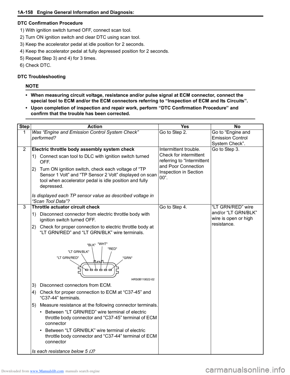
3 Throttle actuator circuit check
1) Disconnect connector from electric throttle body with
ignition switch turned OFF.
2) Check for proper connection to electric throttle body at “LT GRN/RED” and “LT G RN/BLK” wire terminals.
3) Disconnect connectors from ECM.
4) Check for proper connection to ECM at “C37-45” and “C37-44” terminals.
5) Measure resistance at the following connector terminals. • Between “LT GRN/RED” wire terminal of electric throttle body connector and “C37-45” terminal of ECM
connector
• Between “LT GRN/BLK” wire terminal of electric throttle body connector and “C37-44” terminal of ECM
connector
Is each resistance below 5
Ω? Go to Step 4. “LT GRN/RED” wire
and/or “LT GRN/BLK”
wire is open or high
resistance.
"GRN"
"RED"
"WHT"
"BLK"
"LT GRN/BLK"
"LT GRN/RED"
I4RS0B110022-02