Rear end door SUZUKI SWIFT 2005 2.G Service Owner's Guide
[x] Cancel search | Manufacturer: SUZUKI, Model Year: 2005, Model line: SWIFT, Model: SUZUKI SWIFT 2005 2.GPages: 1496, PDF Size: 34.44 MB
Page 1371 of 1496
Downloaded from www.Manualslib.com manuals search engine Hood / Fenders / Doors: 9J-2
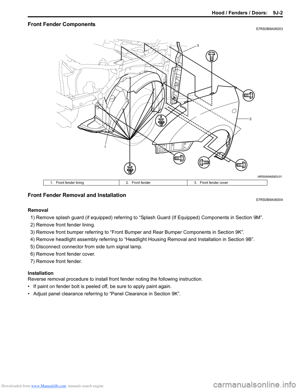
Front Fender ComponentsS7RS0B9A06003
Front Fender Removal and InstallationS7RS0B9A06004
Removal1) Remove splash guard (if equipped) referring to “Splash Guard (If Equipped) Components in Section 9M”.
2) Remove front fender lining.
3) Remove front bumper referring to “Front Bumper and Rear Bumper Components in Section 9K”.
4) Remove headlight assembly referring to “Headlig ht Housing Removal and Installation in Section 9B”.
5) Disconnect connector from side turn signal lamp.
6) Remove front fender cover.
7) Remove front fender.
Installation
Reverse removal procedure to install fron t fender noting the following instruction.
• If paint on fender bolt is peeled off, be sure to apply paint again.
• Adjust panel clearance referring to “Panel Clearance in Section 9K”.
1 2
3
I4RS0A9A0003-01
1. Front fender lining
2. Front fender3. Front fender cover
Page 1374 of 1496
Downloaded from www.Manualslib.com manuals search engine 9J-5 Hood / Fenders / Doors:
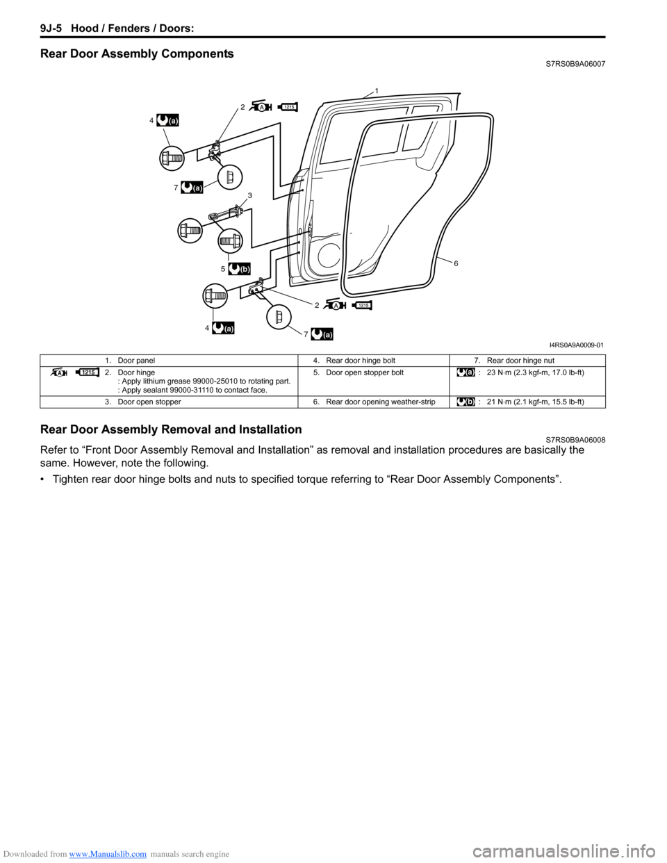
Rear Door Assembly ComponentsS7RS0B9A06007
Rear Door Assembly Removal and InstallationS7RS0B9A06008
Refer to “Front Door Assembly Removal and Installation” as removal and installation procedures are basically the
same. However, note the following.
• Tighten rear door hinge bolts and nuts to specified torque referring to “Rear Door Assembly Components”.
2
2
(a)4
(a)4
(a)7
(a)7
(b)53
6
1
I4RS0A9A0009-01
1. Door panel 4. Rear door hinge bolt7. Rear door hinge nut
2. Door hinge : Apply lithium grease 99000-25010 to rotating part.
: Apply sealant 99000-31110 to contact face. 5. Door open stopper bolt
: 23 N⋅m (2.3 kgf-m, 17.0 lb-ft)
3. Door open stopper 6. Rear door opening weather-strip: 21 N⋅m (2.1 kgf-m, 15.5 lb-ft)
Page 1375 of 1496
Downloaded from www.Manualslib.com manuals search engine Hood / Fenders / Doors: 9J-6
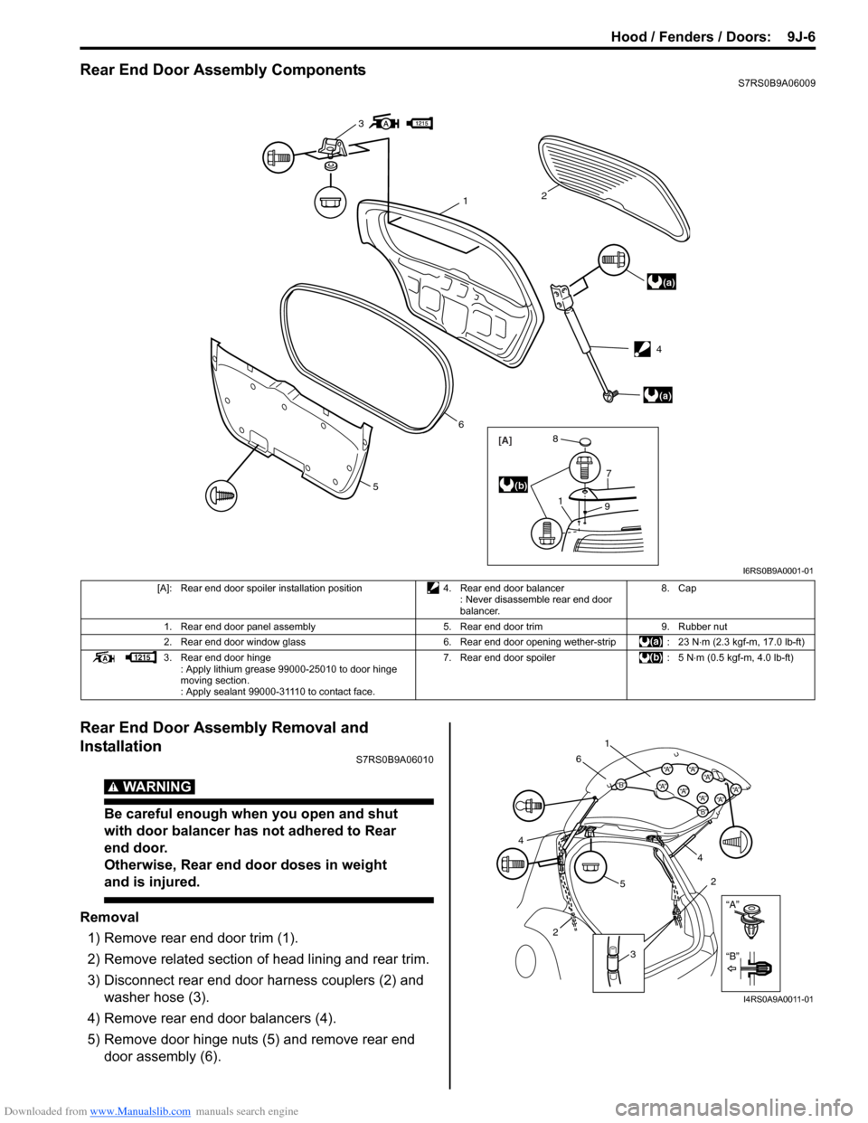
Rear End Door Assembly ComponentsS7RS0B9A06009
Rear End Door Assembly Removal and
Installation
S7RS0B9A06010
WARNING!
Be careful enough when you open and shut
with door balancer has not adhered to Rear
end door.
Otherwise, Rear end door doses in weight
and is injured.
Removal1) Remove rear end door trim (1).
2) Remove related section of head lining and rear trim.
3) Disconnect rear end door harness couplers (2) and washer hose (3).
4) Remove rear end door balancers (4).
5) Remove door hinge nuts (5) and remove rear end door assembly (6).
3
(a)
(a)
12
6
5
[A]
1
7
9
8
(b)
4
I6RS0B9A0001-01
[A]: Rear end door spoiler installation position 4. Rear end door balancer
: Never disassemble rear end door
balancer. 8. Cap
1. Rear end door panel assembly 5. Rear end door trim9. Rubber nut
2. Rear end door window glass 6. Rear end door opening wether-strip: 23 N⋅m (2.3 kgf-m, 17.0 lb-ft)
3. Rear end door hinge : Apply lithium grease 99000-25010 to door hinge
moving section.
: Apply sealant 99000-31110 to contact face. 7. Rear end door spoiler
: 5 N⋅m (0.5 kgf-m, 4.0 lb-ft)
“A”
“B”
“B”
“A”“B”“A”“A”“A”
“A”“A”“A”
“A”
1
6
5 4
2
3
2
4
I4RS0A9A0011-01
Page 1376 of 1496
Downloaded from www.Manualslib.com manuals search engine 9J-7 Hood / Fenders / Doors:
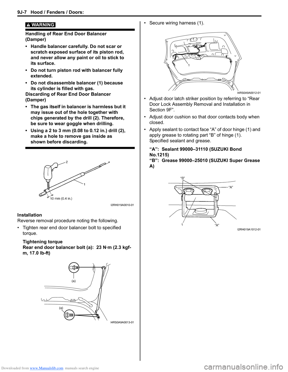
WARNING!
Handling of Rear End Door Balancer
(Damper)
• Handle balancer carefully. Do not scar or scratch exposed surface of its piston rod,
and never allow any paint or oil to stick to
its surface.
• Do not turn piston rod with balancer fully extended.
• Do not disassemble balancer (1) because its cylinder is filled with gas.
Discarding of Rear End Door Balancer
(Damper)
• The gas itself in balancer is harmless but it may issue out of the hole together with
chips generated by th e drill (2). Therefore,
be sure to wear goggle when drilling.
• Using a 2 to 3 mm (0.08 to 0.12 in.) drill (2),
make a hole to remove gas inside as
shown before discarding.
Installation
Reverse removal procedure noting the following.
• Tighten rear end door balancer bolt to specified torque.
Tightening torque
Rear end door balancer bolt (a): 23 N·m (2.3 kgf-
m, 17.0 lb-ft) • Secure wiring harness (1).
• Adjust door latch striker position by referring to “Rear
Door Lock Assembly Removal and Installation in
Section 9F”.
• Adjust door cushion so that door contacts body when closed.
• Apply sealant to contact face “A” of door hinge (1) and apply grease to rotating part “B” of hinge (1).
Specified sealant and grease.
“A”: Sealant 99000–31110 (SUZUKI Bond
No.1215)
“B”: Grease 99000–25010 (SUZUKI Super Grease
A)
I2RH019A0010-01
(a)
(a)
I4RS0A9A0013-01
1
I4RS0A9A0012-01
I2RH019A1012-01
Page 1377 of 1496
Downloaded from www.Manualslib.com manuals search engine Hood / Fenders / Doors: 9J-8
Specifications
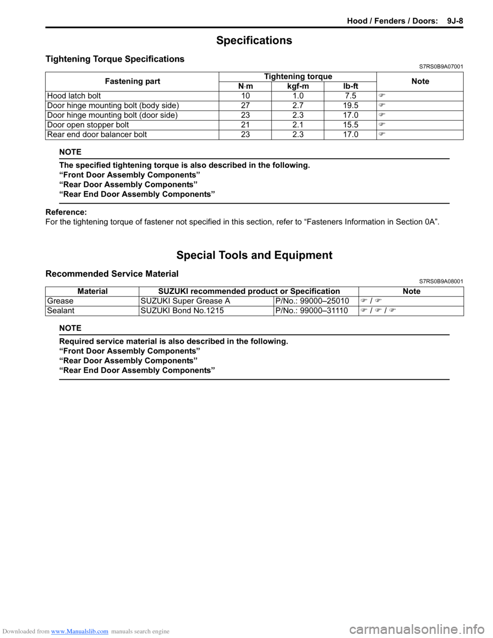
Tightening Torque SpecificationsS7RS0B9A07001
NOTE
The specified tightening torque is also described in the following.
“Front Door Assembly Components”
“Rear Door Assembly Components”
“Rear End Door Assembly Components”
Reference:
For the tightening torque of fastener not specified in this section, refer to “Fasteners Information in Section 0A”.
Special Tools and Equipment
Recommended Service MaterialS7RS0B9A08001
NOTE
Required service material is also described in the following.
“Front Door Assembly Components”
“Rear Door Assembly Components”
“Rear End Door Assembly Components”
Fastening part Tightening torque
Note
N ⋅mkgf-mlb-ft
Hood latch bolt 10 1.0 7.5 �)
Door hinge mounting bolt (body side) 27 2.7 19.5 �)
Door hinge mounting bolt (door side) 23 2.3 17.0 �)
Door open stopper bolt 21 2.1 15.5 �)
Rear end door balancer bolt 23 2.3 17.0 �)
MaterialSUZUKI recommended product or Specification Note
Grease SUZUKI Super Grease A P/No.: 99000–25010�) / �)
Sealant SUZUKI Bond No.1215 P/No.: 99000–31110�) / �) / �)
Page 1381 of 1496
Downloaded from www.Manualslib.com manuals search engine Body Structure: 9K-4
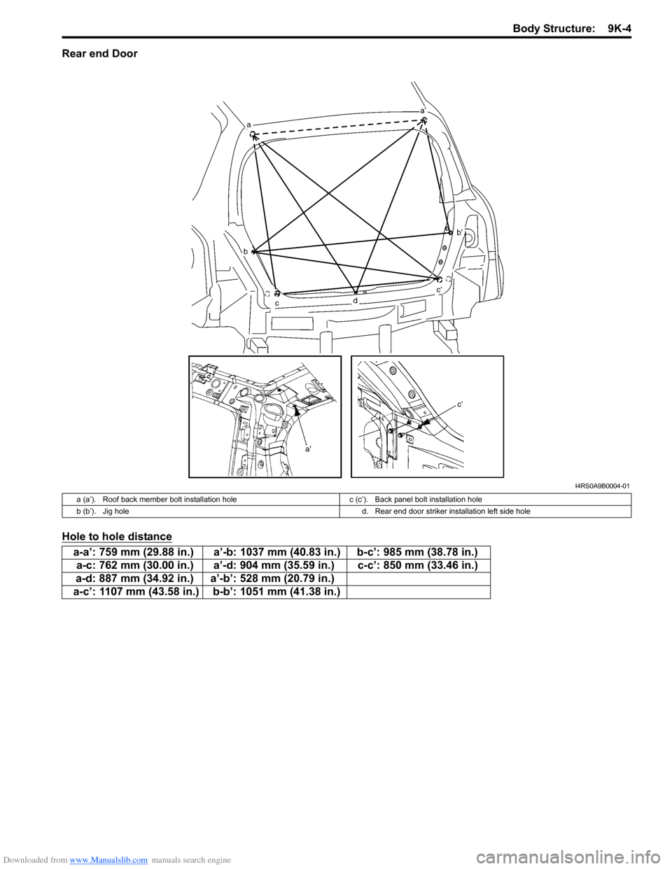
Rear end Door
Hole to hole distance
I4RS0A9B0004-01
a (a’). Roof back member bolt installation holec (c’). Back panel bolt installation hole
b (b’). Jig hole d. Rear end door striker installation left side hole
a-a’: 759 mm (29.88 in.) a’-b: 1037 mm (40.83 in.) b-c’: 985 mm (38.78 in.)
a-c: 762 mm (30.00 in.) a’-d: 904 mm (35.59 in.) c-c’: 850 mm (33.46 in.)
a-d: 887 mm (34.92 in.) a’-b’: 528 mm (20.79 in.)
a-c’: 1107 mm (43.58 in.) b-b’: 1051 mm (41.38 in.)
Page 1402 of 1496
Downloaded from www.Manualslib.com manuals search engine 10-ii Table of Contents
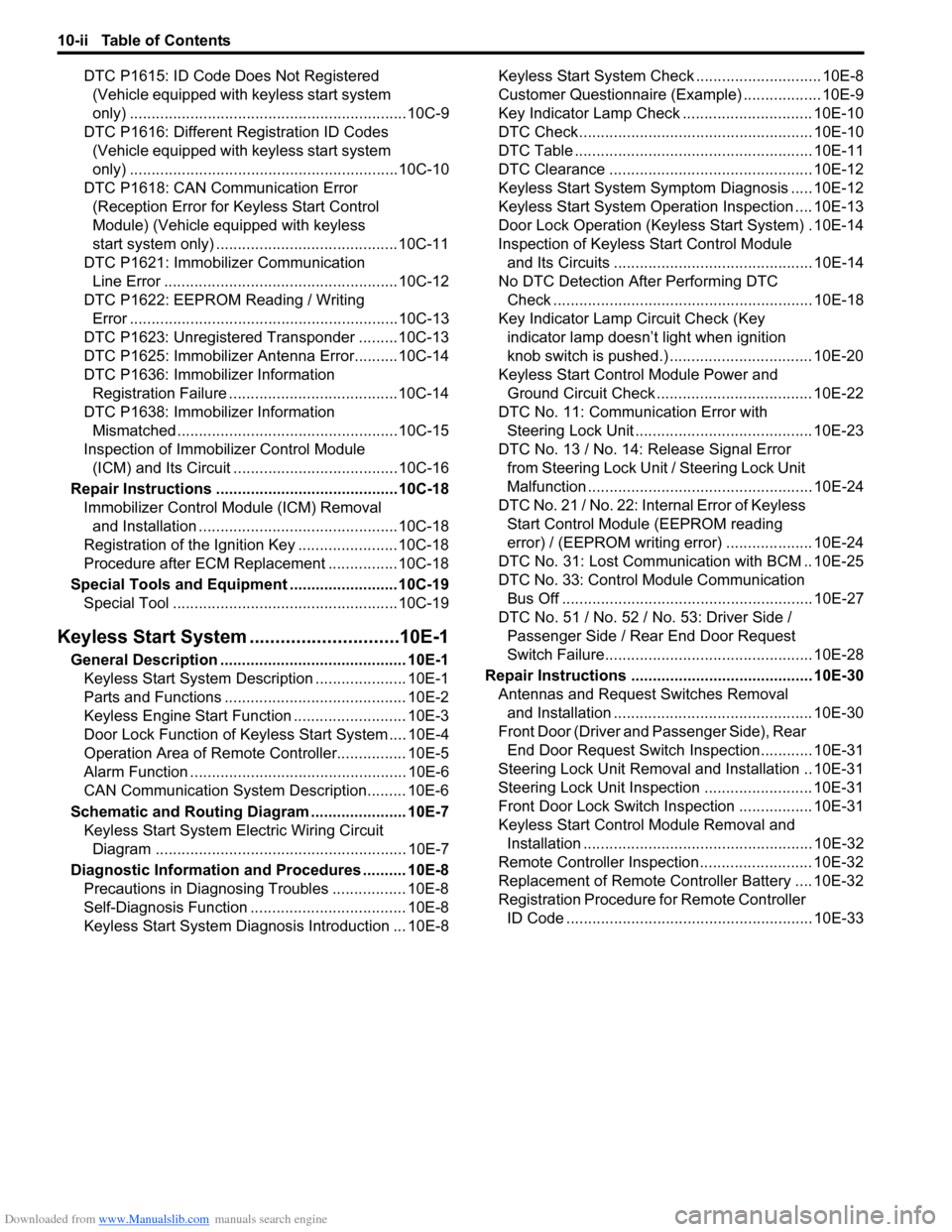
DTC P1615: ID Code Does Not Registered (Vehicle equipped with keyless start system
only) ................................................................10C-9
DTC P1616: Different Registration ID Codes (Vehicle equipped with keyless start system
only) ..............................................................10C-10
DTC P1618: CAN Communication Error (Reception Error for Keyless Start Control
Module) (Vehicle equipped with keyless
start system only) ..........................................10C-11
DTC P1621: Immobilizer Communication Line Error ......................................................10C-12
DTC P1622: EEPROM Reading / Writing Error ..............................................................10C-13
DTC P1623: Unregistered Transponder .........10C-13
DTC P1625: Immobilizer An tenna Error..........10C-14
DTC P1636: Immobilizer Information Registration Failure .......................................10C-14
DTC P1638: Immobilizer Information Mismatched ...................................................10C-15
Inspection of Immobilizer Control Module (ICM) and Its Circuit ....... ...............................10C-16
Repair Instructions ........... ...............................10C-18
Immobilizer Control Mo dule (ICM) Removal
and Installation ..............................................10C-18
Registration of the Ignition Key .......................10C-18
Procedure after ECM Replacement ................10C-18
Special Tools and Equipmen t .........................10C-19
Special Tool ....................................................10C-19
Keyless Start System ....... ......................10E-1
General Description ........................................... 10E-1
Keyless Start System Description ..................... 10E-1
Parts and Functions .......................................... 10E-2
Keyless Engine Start Function .......................... 10E-3
Door Lock Function of Keyless Start System .... 10E-4
Operation Area of Remote Controller................ 10E-5
Alarm Function .................................................. 10E-6
CAN Communication System Description......... 10E-6
Schematic and Routing Diagram ...................... 10E-7 Keyless Start System El ectric Wiring Circuit
Diagram .......................................................... 10E-7
Diagnostic Information and Procedures .......... 10E-8 Precautions in Diagnosing Troubles ................. 10E-8
Self-Diagnosis Function .................................... 10E-8
Keyless Start System Diagn osis Introduction ... 10E-8 Keyless Start System Chec
k ............................. 10E-8
Customer Questionnaire (E xample) .................. 10E-9
Key Indicator Lamp Check .............................. 10E-10
DTC Check...................................................... 10E-10
DTC Table ....................................................... 10E-11
DTC Clearance ............................................... 10E-12
Keyless Start System Symp tom Diagnosis ..... 10E-12
Keyless Start System Operation Inspection .... 10E-13
Door Lock Operation (Keyless Start System) . 10E-14
Inspection of Keyless Start Control Module and Its Circuits .............................................. 10E-14
No DTC Detection After Performing DTC Check ............................................................ 10E-18
Key Indicator Lamp Circuit Check (Key indicator lamp doesn’t light when ignition
knob switch is pushed.) ................................. 10E-20
Keyless Start Control Module Power and Ground Circuit Check .................................... 10E-22
DTC No. 11: Communi cation Error with
Steering Lock Unit ......................................... 10E-23
DTC No. 13 / No. 14: Release Signal Error from Steering Lock Unit / Steering Lock Unit
Malfunction .................................................... 10E-24
DTC No. 21 / No. 22: Internal Error of Keyless Start Control Module (EEPROM reading
error) / (EEPROM writing error) ............ ........ 10E-24
DTC No. 31: Lost Commun ication with BCM .. 10E-25
DTC No. 33: Control Module Communication
Bus Off .......................................................... 10E-27
DTC No. 51 / No. 52 / No. 53: Driver Side / Passenger Side / Rear End Door Request
Switch Failure................................................ 10E-28
Repair Instructions ............ .............................. 10E-30
Antennas and Request Switches Removal and Installation .............................................. 10E-30
Front Door (Driver and Passenger Side), Rear End Door Request Switch Inspection............ 10E-31
Steering Lock Unit Removal and Installation .. 10E-31
Steering Lock Unit Inspection ......................... 10E-31
Front Door Lock Switch In spection ................. 10E-31
Keyless Start Control Module Removal and Installation ..................................................... 10E-32
Remote Controller Inspection.......................... 10E-32
Replacement of Remote Controller Battery .... 10E-32
Registration Procedure for Remote Controller
ID Code ......................................................... 10E-33
Page 1404 of 1496
Downloaded from www.Manualslib.com manuals search engine 10B-1 Body Electrical Control System:
Control Systems
Body Electrical Control System
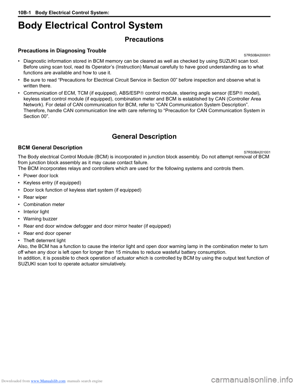
Precautions
Precautions in Diagnosing TroubleS7RS0BA200001
• Diagnostic information stored in BCM memory can be cleared as well as checked by using SUZUKI scan tool.
Before using scan tool, read its Operator ’s (Instruction) Manual carefully to have good understanding as to what
functions are available and how to use it.
• Be sure to read “Precautions for Electrical Circuit Serv ice in Section 00” before inspection and observe what is
written there.
• Communication of ECM, TCM (if equipped), ABS/ESP ® control module, steering angle sensor (ESP ® model),
keyless start control module (if equipped), combinatio n meter and BCM is established by CAN (Controller Area
Network). For detail of CAN communication for BCM, refer to “CAN Communication System Description”.
Therefore, handle CAN communication line with care referr ing to “Precaution for CAN Communication System in
Section 00”.
General Description
BCM General DescriptionS7RS0BA201001
The Body electrical Control Module (BCM) is incorporated in junction block assembly. Do not attempt removal of BCM
from junction block assembly as it may cause contact failure.
The BCM incorporates relays and controllers which are used for the following systems and controls them.
• Power door lock
• Keyless entry (if equipped)
• Door lock function of keyle ss start system (if equipped)
• Rear wiper
• Combination meter
• Interior light
• Warning buzzer
• Rear end door window defogger and door mirror heater (if equipped)
• Rear end door opener
• Theft deterrent light
Also, the BCM has a function to cause the interior light and open door warning lamp in the combination meter to turn
off when any door is left open for longer than 15 minutes to reduce wasteful battery consumption.
In addition, it is possible to check operation of actuator whic h is controlled by BCM by using the output test function of
SUZUKI scan tool to operate actuator simulatively.
Page 1409 of 1496
![SUZUKI SWIFT 2005 2.G Service Owners Guide Downloaded from www.Manualslib.com manuals search engine Body Electrical Control System: 10B-6
[A]: Vehicle not equipped with diagnosis connector 19. Door key cylinder switch (included in door lock a SUZUKI SWIFT 2005 2.G Service Owners Guide Downloaded from www.Manualslib.com manuals search engine Body Electrical Control System: 10B-6
[A]: Vehicle not equipped with diagnosis connector 19. Door key cylinder switch (included in door lock a](/img/20/7607/w960_7607-1408.png)
Downloaded from www.Manualslib.com manuals search engine Body Electrical Control System: 10B-6
[A]: Vehicle not equipped with diagnosis connector 19. Door key cylinder switch (included in door lock actuator)40. SDM
[B]: Vehicle equipped with diagnosis conn ector 20. Manual door lock switch 41. Rear end door window defogger relay
[C]: ESP ® model 21. Rear end door window defogger switch 42. Rear end door window defogger
1. BCM (included in junction block assembly) 22. Rear end door opener switch 43. Rear end door window defogger indicator lamp
2. Rear washer motor 23. “3” position switch (A/T model)44. Horn relay
3. Rear wiper motor 24. A/C switch45. Horn switch
4. Rear wiper relay 25. Rear end door opener relay46. Horn
5. Rear wiper and washer switch 26. Rear end door opener actuator47. Lighting switch
6. Outside air temperature sensor 27. TCM (A/T model)48. Ignition switch
7. Key reminder switch 28. ECM49. Battery
8. Theft deterrent light 29. Combination meter50. To turn signal light
9. Oil pressure switch 30. Data link connector (DLC)51. Body ground
10. Generator 31. To ECM, ABS/ESP®, P/S control module 52. Engine ground
11. Information display (if equipped) 32. To SDM53. Keyless start control module (if equipped)
12. Keyless entry receiver (if equipped) 33. Door lock actuator relay 54. Right side door mirror heater (if equipped)
13. Driver side door switch 34. Driver side door lock actuator55. Left side door mirror heater (if equipped)
14. Other than driver side door switch 35. Passenger side door lock actuator56. ABS/ESP® control module
15. Rear end door switch 36. Rear door lock actuator57. To HVAC control module
16. Driver side seat belt switch 37. Turn signal and hazard warning relay 58. CAN junction connector
17. Brake fluid level switch 38. Hazard warning switch59. Steering angle sensor
18. Parking brake switch 39. Interior light
Page 1410 of 1496
Downloaded from www.Manualslib.com manuals search engine 10B-7 Body Electrical Control System:
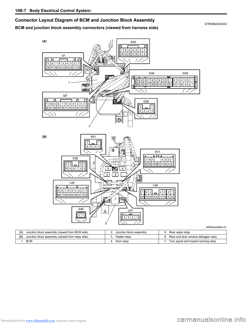
Connector Layout Diagram of BCM and Junction Block AssemblyS7RS0BA202002
BCM and junction block assembly connectors (viewed from harness side)
I4RS0AA20004-01
[A]: Junction block assembly (viewed from BCM side)2. Junction block assembly5. Rear wiper relay
[B]: Junction block assembly (viewed from relay side) 3.Heater relay 6. Rear end door window defogger relay
1. BCM 4. Horn relay7. Turn signal and hazard warning relay