front suspension SUZUKI SWIFT 2005 2.G Service Owner's Guide
[x] Cancel search | Manufacturer: SUZUKI, Model Year: 2005, Model line: SWIFT, Model: SUZUKI SWIFT 2005 2.GPages: 1496, PDF Size: 34.44 MB
Page 456 of 1496
Downloaded from www.Manualslib.com manuals search engine 2C-2 Rear Suspension:
Repair Instructions
Rear Wheel Alignment InspectionS7RS0B2306017
Measure toe and camber referring to “Front Wheel
Alignment Inspection and Adjustment in Section 2B”.
NOTE
Rear suspension is not adjustable structure.
Rear toe (total)
: IN 3.8 ± 3.8 mm (IN 0.1969 ± 0.1969 in)
Rear camber
: –1 ° ± 1
If measured value is out of specified value, check
following items for damage, deformation and crack.
• Rear axle (torsion beam)
• Spindle, wheel hub or wheel bearing
• Vehicle body
Rear Shock Absorber Removal and InstallationS7RS0B2306001
Removal 1) Hoist vehicle and remove rear wheels.
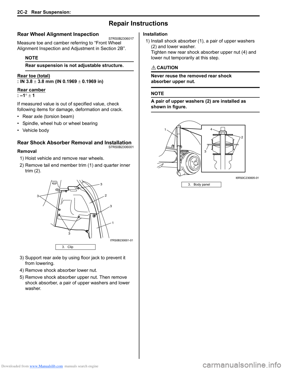
2) Remove tail end member trim (1) and quarter inner trim (2).
3) Support rear axle by using floor jack to prevent it from lowering.
4) Remove shock absorber lower nut.
5) Remove shock absorber upper nut. Then remove shock absorber, a pair of upper washers and lower
washer. Installation
1) Install shock absorber (1), a pair of upper washers (2) and lower washer.
Tighten new rear shock absorber upper nut (4) and
lower nut temporarily at this step.
CAUTION!
Never reuse the removed rear shock
absorber upper nut.
NOTE
A pair of upper washers (2) are installed as
shown in figure.
3. Clip
3
3 2
3
1
3
I7RS0B230001-01
3. Body panel
14
3 2
I6RS0C230005-01
Page 459 of 1496
Downloaded from www.Manualslib.com manuals search engine Rear Suspension: 2C-5
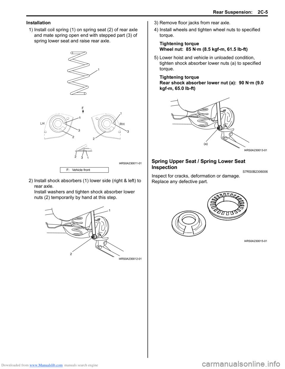
Installation1) Install coil spring (1) on spring seat (2) of rear axle and mate spring open end with stepped part (3) of
spring lower seat and raise rear axle.
2) Install shock absorbers (1) lower side (right & left) to rear axle.
Install washers and tighten shock absorber lower
nuts (2) temporarily by hand at this step. 3) Remove floor jacks from rear axle.
4) Install wheels and tighten wheel nuts to specified
torque.
Tightening torque
Wheel nut: 85 N·m (8.5 kgf-m, 61.5 lb-ft)
5) Lower hoist and vehicle in unloaded condition, tighten shock absorber lower nuts (a) to specified
torque.
Tightening torque
Rear shock absorber lower nut (a): 90 N·m (9.0
kgf-m, 65.0 lb-ft)
Spring Upper Seat / Spring Lower Seat
Inspection
S7RS0B2306006
Inspect for cracks, deformation or damage.
Replace any defective part.
F: Vehicle front
I4RS0A230011-01
1
2
I4RS0A230012-01
(a)
I4RS0A230013-01
I4RS0A230015-01
Page 460 of 1496
Downloaded from www.Manualslib.com manuals search engine 2C-6 Rear Suspension:
Spring Upper Seat and Lower Seat Removal and
Installation
S7RS0B2306007
Removal1) Remove coil spring referring to “Rear Coil Spring Removal and Installation”.
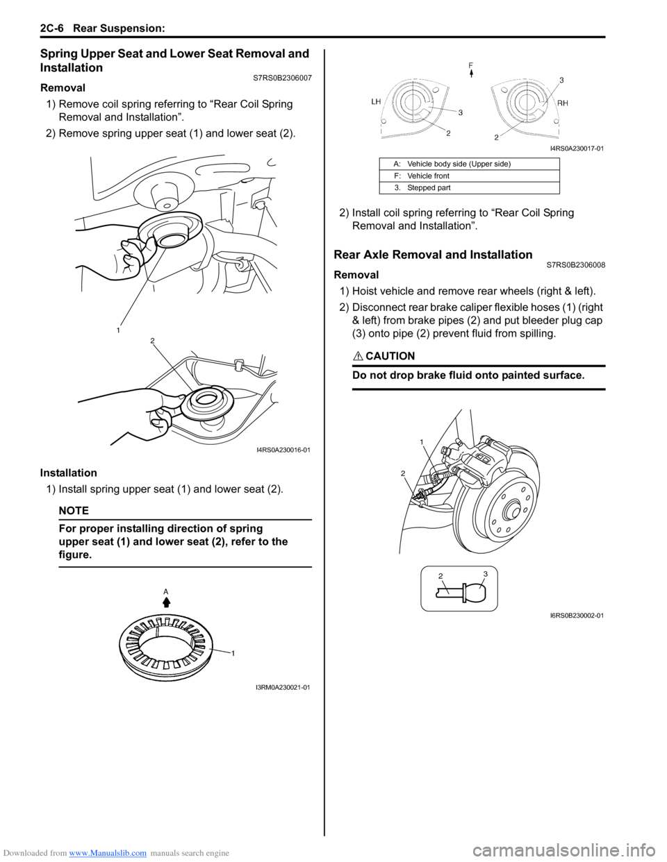
2) Remove spring upper seat (1) and lower seat (2).
Installation 1) Install spring upper seat (1) and lower seat (2).
NOTE
For proper installing direction of spring
upper seat (1) and lower seat (2), refer to the
figure.
2) Install coil spring referr ing to “Rear Coil Spring
Removal and Installation”.
Rear Axle Removal and InstallationS7RS0B2306008
Removal
1) Hoist vehicle and remove rear wheels (right & left).
2) Disconnect rear brake caliper flexible hoses (1) (right & left) from brake pipes (2) and put bleeder plug cap
(3) onto pipe (2) prevent fluid from spilling.
CAUTION!
Do not drop brake fluid onto painted surface.
1
2
I4RS0A230016-01
I3RM0A230021-01
A: Vehicle body side (Upper side)
F: Vehicle front3. Stepped part
I4RS0A230017-01
1
2
2 3
I6RS0B230002-01
Page 482 of 1496
Downloaded from www.Manualslib.com manuals search engine 3A-4 Drive Shaft / Axle:
Front Drive Shaft Assembly On-Vehicle
Inspection
S7RS0B3106002
• Check boots for breakage or deterioration.
• Check wheel side joint for rattle or smooth rotation.
• Check differential side (or center shaft side) joint for smooth rotation.
If any abnormality is found, replace.
Front Drive Shaft Assembly Removal and
Installation
S7RS0B3106003
Removal
1) Hoist vehicle and remove wheel.
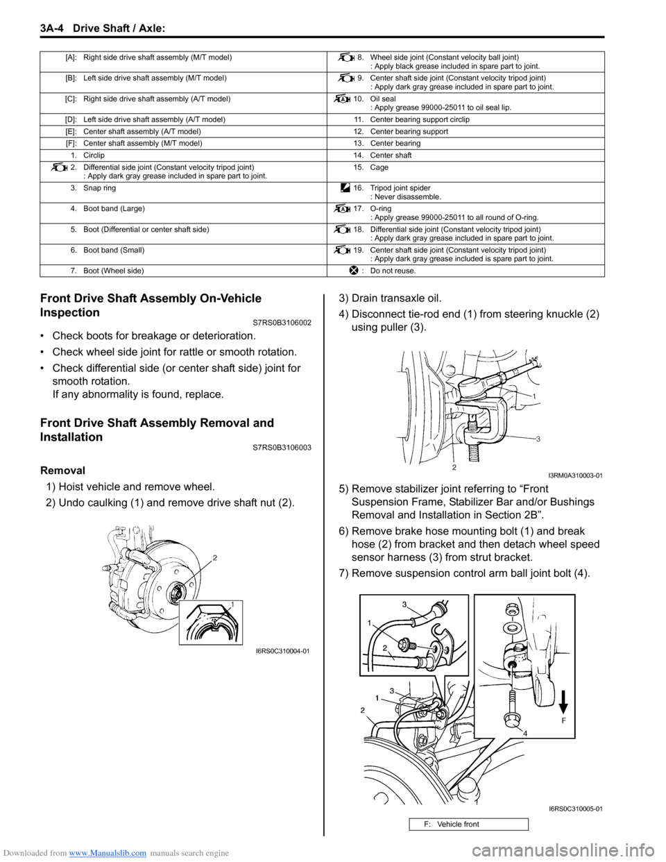
2) Undo caulking (1) and remove drive shaft nut (2). 3) Drain transaxle oil.
4) Disconnect tie-rod end (1) from steering knuckle (2)
using puller (3).
5) Remove stabilizer join t referring to “Front
Suspension Frame, Stabiliz er Bar and/or Bushings
Removal and Installati on in Section 2B”.
6) Remove brake hose mounting bolt (1) and break hose (2) from bracket and then detach wheel speed
sensor harness (3) from strut bracket.
7) Remove suspension contro l arm ball joint bolt (4).
[A]: Right side drive shaft assembly (M/T model) 8. Wheel side joint (Constant velocity ball joint)
: Apply black grease included in spare part to joint.
[B]: Left side drive shaft assembly (M/T model) 9. Center shaft side joint (Constant velocity tripod joint)
: Apply dark gray grease included in spare part to joint.
[C]: Right side drive shaft assembly (A/T model) 10. Oil seal
: Apply grease 99000-25011 to oil seal lip.
[D]: Left side drive shaft assembly (A/T model) 11. Center bearing support circlip
[E]: Center shaft assembly (A/T model) 12. Center bearing support
[F]: Center shaft assembly (M/T model) 13. Center bearing
1. Circlip 14. Center shaft
2. Differential side joint (Constant velocity tripod joint) : Apply dark gray grease included in spare part to joint. 15. Cage
3. Snap ring 16. Tripod joint spider
: Never disassemble.
4. Boot band (Large) 17. O-ring
: Apply grease 99000-25011 to all round of O-ring.
5. Boot (Differential or center shaft side) 18. Differential side joint (Constant velocity tripod joint)
: Apply dark gray grease included in spare part to joint.
6. Boot band (Small) 19. Center shaft side joint (Constant velocity tripod joint)
: Apply dark gray grease included is spare part to joint.
7. Boot (Wheel side) : Do not reuse.
I6RS0C310004-01
F: Vehicle front
I3RM0A310003-01
I6RS0C310005-01
Page 483 of 1496
Downloaded from www.Manualslib.com manuals search engine Drive Shaft / Axle: 3A-5
8) Disconnect front suspension control arm ball joint
stud from steering knuckle.
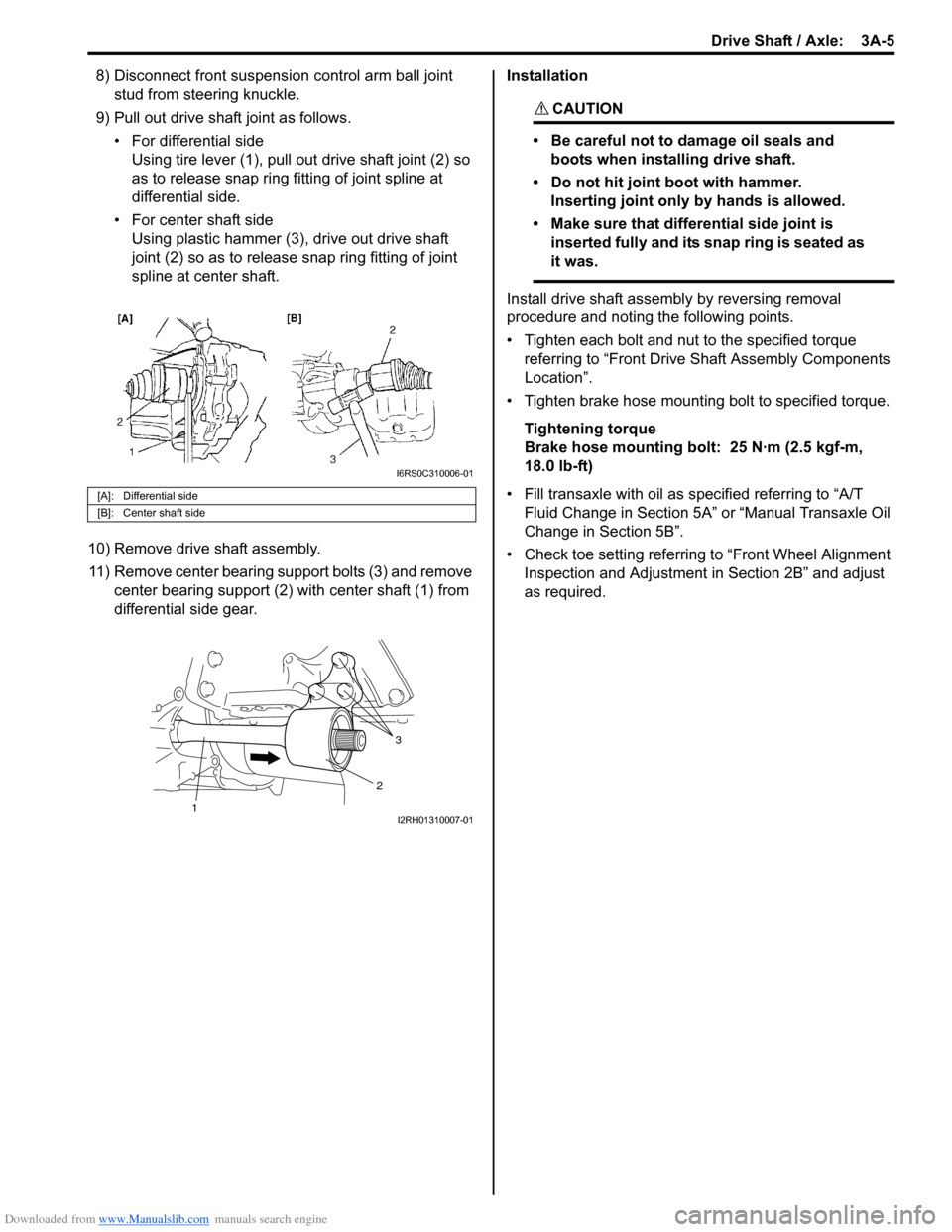
9) Pull out drive shaft joint as follows. • For differential sideUsing tire lever (1), pull out drive shaft joint (2) so
as to release snap ring fitting of joint spline at
differential side.
• For center shaft side Using plastic hammer (3), drive out drive shaft
joint (2) so as to release snap ring fitting of joint
spline at center shaft.
10) Remove drive shaft assembly. 11) Remove center bearing support bolts (3) and remove center bearing support (2) with center shaft (1) from
differential side gear. Installation
CAUTION!
• Be careful not to damage oil seals and
boots when installing drive shaft.
• Do not hit joint boot with hammer. Inserting joint only by hands is allowed.
• Make sure that differential side joint is inserted fully and its snap ring is seated as
it was.
Install drive shaft assemb ly by reversing removal
procedure and noting the following points.
• Tighten each bolt and nut to the specified torque referring to “Front Drive Shaft Assembly Components
Location”.
• Tighten brake hose mounting bolt to specified torque.
Tightening torque
Brake hose mounting bolt: 25 N·m (2.5 kgf-m,
18.0 lb-ft)
• Fill transaxle with oil as sp ecified referring to “A/T
Fluid Change in Section 5A” or “Manual Transaxle Oil
Change in Section 5B”.
• Check toe setting referring to “Front Wheel Alignment Inspection and Adjustment in Section 2B” and adjust
as required.
[A]: Differential side
[B]: Center shaft side
I6RS0C310006-01
3
2
1I2RH01310007-01
Page 502 of 1496
Downloaded from www.Manualslib.com manuals search engine 4A-4 Brake Control System and Diagnosis:
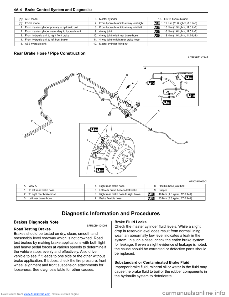
Rear Brake Hose / Pipe ConstructionS7RS0B4101003
Diagnostic Information and Procedures
Brakes Diagnosis NoteS7RS0B4104001
Road Testing Brakes
Brakes should be tested on dry, clean, smooth and
reasonably level roadway which is not crowned. Road
test brakes by making brake applications with both light
and heavy pedal forces at vari ous speeds to determine if
the vehicle stops evenly and effectively. Also drive
vehicle to see if it leads to one side or the other without
brake application. If it does, check the tire pressure, front
wheel alignment and front suspension attachments for
looseness. See diagnosis table for other causes. Brake Fluid Leaks
Check the master cylinder fl
uid levels. While a slight
drop in reservoir level does result from normal lining
wear, an abnormally low leve l indicates a leak in the
system. In such a case, chec k the entire brake system
for leakage. If even a slight ev idence of leakage is noted,
the cause should be corrected or defective parts should
be replaced.
Substandard or Contaminated Brake Fluid
Improper brake fluid, mineral oil or water in the fluid may
cause the brake fluid to boil or the rubber components in
the hydraulic system to deteriorate.
[A]: ABS model 6. Master cylinder13. ESP® hydraulic unit
[B]: ESP ® model 7. From hydraulic unit to 4-way joint right : 11 N⋅m (11.0 kgf-m, 8.0 lb-ft)
1. From master cylinder primary to hydraulic unit 8. From hydraulic unit to 4-way joint left: 15 N⋅m (1.5 kgf-m, 11.0 lb-ft)
2. From master cylinder secondary to hydraulic unit 9. 4-way joint: 16 N⋅m (1.6 kgf-m, 11.5 lb-ft)
3. From hydraulic unit to right front brake 10.4-way joint to left rear brake hose : 19 N⋅m (1.9 kgf-m, 14.0 lb-ft)
4. From hydraulic unit to left front brake 11. 4-way joint to right rear brake hose
5. ABS hydraulic unit 12. Master cylinder fixing nut
I6RS0C410003-01
A: View A4. Right rear brake hose8. Flexible hose joint bolt
1. To left rear brake hose 5. Left rear brake hose to left brake9. Caliper
2. To right rear brake hose 6. Right rear brake hose to right brake: 16 N⋅m (1.6 kgf-m, 12.0 lb-ft)
3. Left rear brake hose 7. Brake flexible hose: 23 N⋅m (2.3 kgf-m, 17.0 lb-ft)
Page 503 of 1496
Downloaded from www.Manualslib.com manuals search engine Brake Control System and Diagnosis: 4A-5
If deterioration of rubber is evident, disassemble all
hydraulic parts and wash with alcohol. Dry these parts
with compressed air before assembly to keep alcohol out
of the system. Replace all rubber parts in the system,
including hoses. Also, when working on the brake
mechanisms, check for fluid on the linings.
If excessive fluid is found, replace the pads. If master cylinder piston seals
are satisfactory, check for
leakage or excessive heat co nditions. If leakage is not
found, drain fluid, flush with brake fluid, refill and bleed
system.
The system must be flushed if there is any doubt as to
the grade of fluid in the system or if fluid has been used
which contained parts that have been subjected to
contaminated fluid.
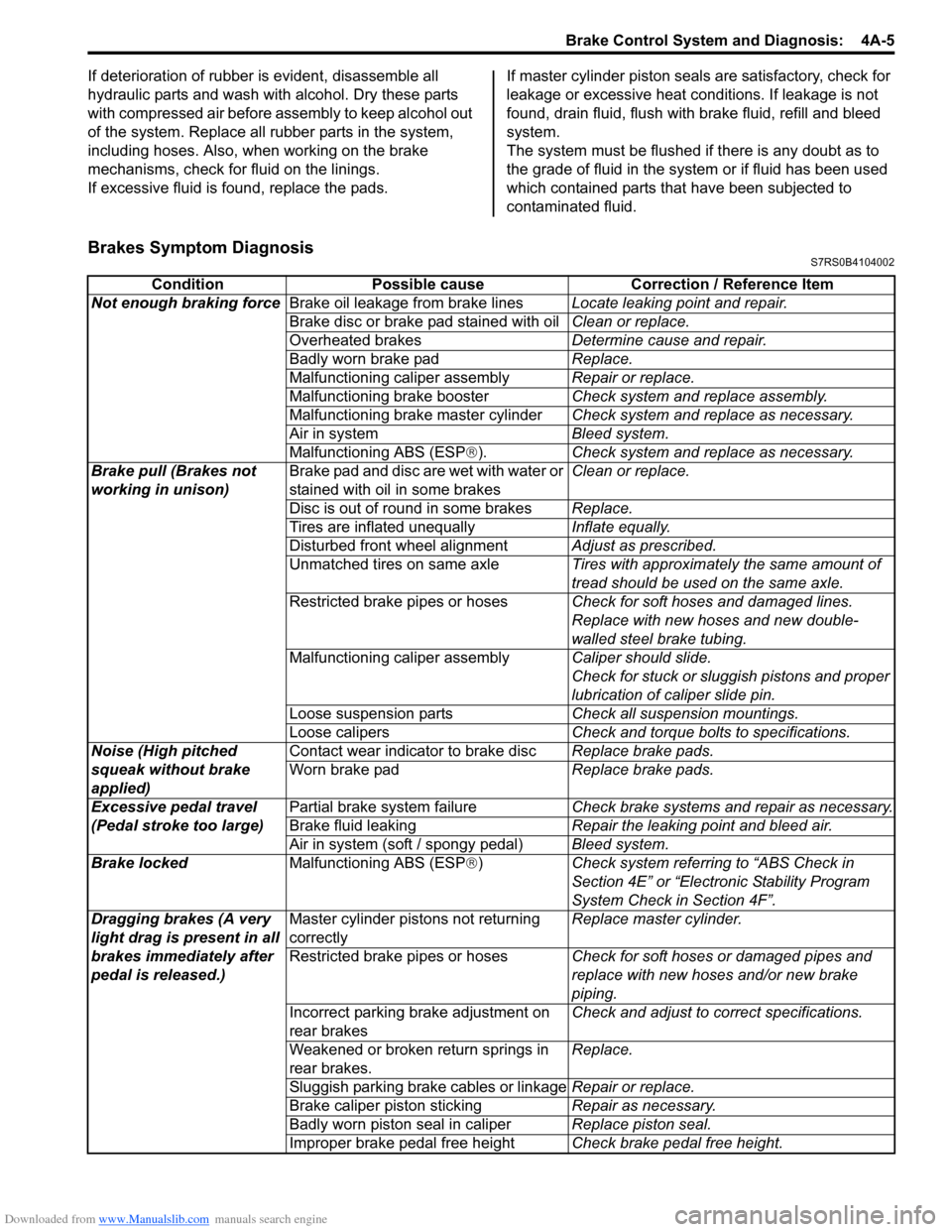
Brakes Symptom DiagnosisS7RS0B4104002
Condition Possible cause Correction / Reference Item
Not enough braking force Brake oil leakage from brake lines Locate leaking point and repair.
Brake disc or brake pad stained with oil Clean or replace.
Overheated brakes Determine cause and repair.
Badly worn brake pad Replace.
Malfunctioning caliper assembly Repair or replace.
Malfunctioning brake booster Check system and replace assembly.
Malfunctioning brake master cylinder Check system and replace as necessary.
Air in system Bleed system.
Malfunctioning ABS (ESP ®). Check system and replace as necessary.
Brake pull (Brakes not
working in unison) Brake pad and disc are wet with water or
stained with oil in some brakes Clean or replace.
Disc is out of round in some brakes Replace.
Tires are inflated unequally Inflate equally.
Disturbed front wheel alignment Adjust as prescribed.
Unmatched tires on same axle Tires with approximately the same amount of
tread should be used on the same axle.
Restricted brake pipes or hoses Check for soft hoses and damaged lines.
Replace with new hoses and new double-
walled steel brake tubing.
Malfunctioning caliper assembly Caliper should slide.
Check for stuck or sluggish pistons and proper
lubrication of caliper slide pin.
Loose suspension parts Check all suspension mountings.
Loose calipers Check and torque bolts to specifications.
Noise (High pitched
squeak without brake
applied) Contact wear indicator to brake disc
Replace brake pads.
Worn brake pad Replace brake pads.
Excessive pedal travel
(Pedal stroke too large) Partial brake system failure
Check brake systems and repair as necessary.
Brake fluid leaking Repair the leaking point and bleed air.
Air in system (soft / spongy pedal) Bleed system.
Brake locked Malfunctioning ABS (ESP®) Check system referri ng to “ABS Check in
Section 4E” or “Electronic Stability Program
System Check in Section 4F”.
Dragging brakes (A very
light drag is present in all
brakes immediately after
pedal is released.) Master cylinder pistons not returning
correctly
Replace master cylinder.
Restricted brake pipes or hoses Check for soft hoses or damaged pipes and
replace with new hoses and/or new brake
piping.
Incorrect parking brake adjustment on
rear brakes Check and adjust to correct specifications.
Weakened or broken return springs in
rear brakes. Replace.
Sluggish parking brake cables or linkage Repair or replace.
Brake caliper piston sticking Repair as necessary.
Badly worn piston seal in caliper Replace piston seal.
Improper brake pedal free height Check brake pedal free height.
Page 508 of 1496
Downloaded from www.Manualslib.com manuals search engine 4A-10 Brake Control System and Diagnosis:
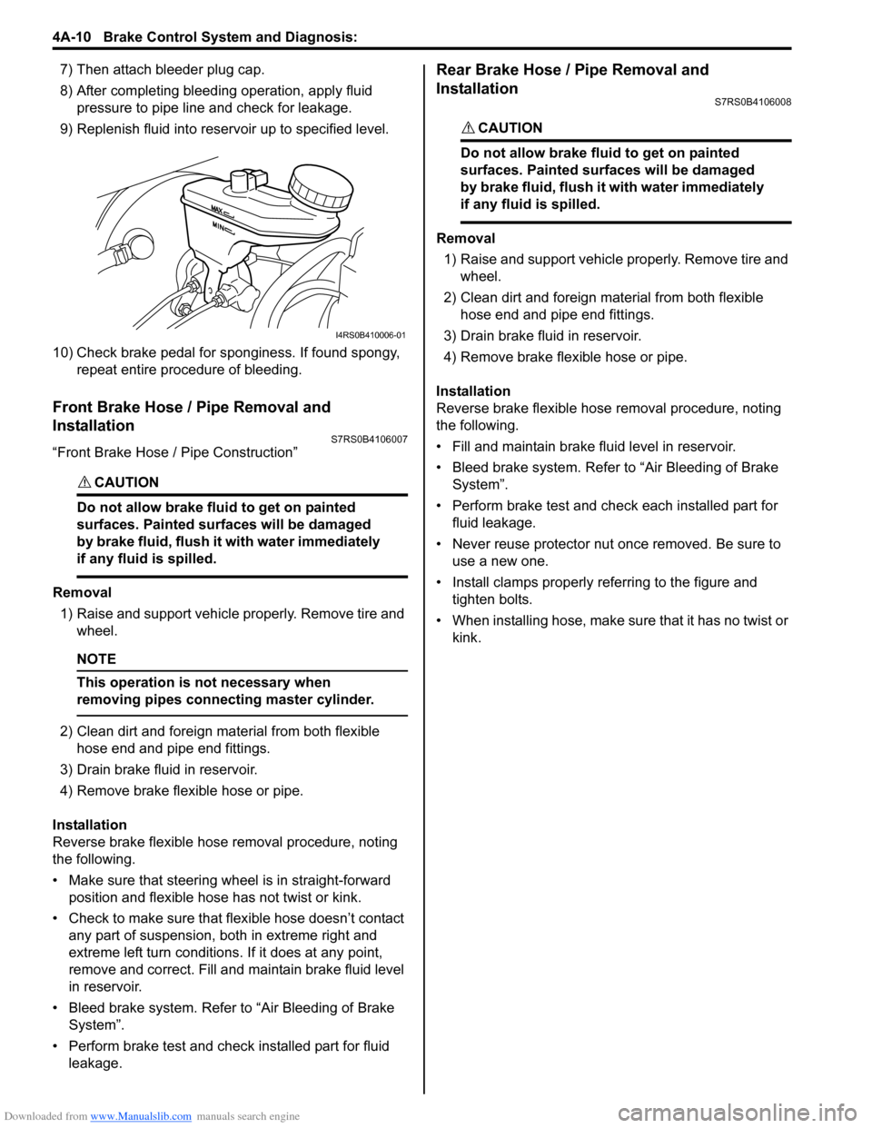
7) Then attach bleeder plug cap.
8) After completing bleeding operation, apply fluid pressure to pipe line and check for leakage.
9) Replenish fluid into reserv oir up to specified level.
10) Check brake pedal for sponginess. If found spongy, repeat entire procedure of bleeding.
Front Brake Hose / Pipe Removal and
Installation
S7RS0B4106007
“Front Brake Hose / Pipe Construction”
CAUTION!
Do not allow brake fluid to get on painted
surfaces. Painted surfaces will be damaged
by brake fluid, flush it with water immediately
if any fluid is spilled.
Removal
1) Raise and support vehicle properly. Remove tire and wheel.
NOTE
This operation is not necessary when
removing pipes connecting master cylinder.
2) Clean dirt and foreign mate rial from both flexible
hose end and pipe end fittings.
3) Drain brake fluid in reservoir.
4) Remove brake flexible hose or pipe.
Installation
Reverse brake flexible hose removal procedure, noting
the following.
• Make sure that steering wh eel is in straight-forward
position and flexible hose has not twist or kink.
• Check to make sure that flexible hose doesn’t contact any part of suspension, both in extreme right and
extreme left turn conditions. If it does at any point,
remove and correct. Fill and maintain brake fluid level
in reservoir.
• Bleed brake system. Refer to “Air Bleeding of Brake System”.
• Perform brake test and check installed part for fluid leakage.
Rear Brake Hose / Pipe Removal and
Installation
S7RS0B4106008
CAUTION!
Do not allow brake fluid to get on painted
surfaces. Painted surfaces will be damaged
by brake fluid, flush it with water immediately
if any fluid is spilled.
Removal
1) Raise and support vehicle properly. Remove tire and wheel.
2) Clean dirt and foreign material from both flexible hose end and pipe end fittings.
3) Drain brake fluid in reservoir.
4) Remove brake flexible hose or pipe.
Installation
Reverse brake flexible hose removal procedure, noting
the following.
• Fill and maintain brake fluid level in reservoir.
• Bleed brake system. Refer to “Air Bleeding of Brake System”.
• Perform brake test and check each installed part for fluid leakage.
• Never reuse protector nut once removed. Be sure to use a new one.
• Install clamps properly referring to the figure and tighten bolts.
• When installing hose, make sure that it has no twist or
kink.
I4RS0B410006-01
Page 662 of 1496

Downloaded from www.Manualslib.com manuals search engine 5A-18 Automatic Transmission/Transaxle:
Visual InspectionS7RS0B5104002
Visually check the following parts and systems.
Malfunction Indicator Lamp (MIL) CheckS7RS0B5104003
Refer to the same item in “Malfunction Indicator Lam p (MIL) Check in Section 1A” for checking procedure.
Transmission Warning Light CheckS7RS0B5104004
1) Turn ignition switch ON.
2) Check that transmission warning light lights for about 2 – 4 sec. and then goes OFF.
If anything faulty is found, advance “Transmission Warn ing Light Circuit Check – Light Does Not Come “ON” at
Ignition Switch ON” or “Transmission Warning Light Circu it Check – Light Remains “ON” at Ignition Switch ON”.
Inspection item Referring
• A/T fluid ----- level, leakage, color “Automatic Transaxle Fluid Level Inspection in Section 0B”
• A/T fluid hoses ----- disconnection, looseness, deterioration “A/T Fluid Cooler Hoses Replacement”
• A/T select cable ----- installation “S elect Cable Removal and Installation”
• Engine oil ----- level, leakage “Engine Oil and Filter Change in Section 0B”
• Engine coolant ----- level, leakage “Engine Coolant Change in Section 0B”
• Engine mountings ----- play, looseness, damage “Engine Assembly Removal and Installation in Section 1D”
• Suspension ----- play, looseness “Suspension, Wheels and Tires Symptom Diagnosis in Section 2A”
• Drive shafts ----- damage “Front Drive Shaft Assembly On-Vehicle Inspection in Section 3A”
• Battery ----- indicator condition, corrosion of terminal “Battery Inspection in Section 1J”
• Connectors of electric wire harness ----- disconnection, friction “Electronic Shift Control System Components
Location”
• Fuses ----- burning
• Parts ----- installation, damage
• Bolts ----- looseness
• Other parts that can be checked visually
Also check the following items at engine start, if possible.
• Transmission warning light (if equipped) ----- Operation “Transmission Warning Light Check”
• Malfunction indicator lamp ----- Operation “Malfunction Indicator Lamp (MIL) Check”
• Charge warning lamp ----- Operation “Generator Symptom Diagnosis in Section 1J”
• Engine oil pressure warning lamp ----- Operation “Oil Pressure Warning Ligh t Symptom Diagnosis in
Section 9C”
• Engine coolant temp. meter ----- Operation “Engine Coolant Temperature (ECT) Meter
Symptom Diagnosis in Section 9C”
• Other parts that can be checked visually
I4RS0A510008-01
Page 871 of 1496

Downloaded from www.Manualslib.com manuals search engine Steering General Diagnosis: 6A-2
Diagnostic Information and Procedures
Steering Symptom DiagnosisS7RS0B6104001
ConditionPossible cause Correction / Reference Item
Hard steering Tire not adequately inflated Inflate tires to proper pressure.
Malfunction of power steering system Check and correct.
Bind in tie-rod end ball studs or lower
ball joints Replace tie-rod end or front suspension arm.
Disturbed front wheel alignment Check and adjust front wheel alignment.
Bind in steering column Repair or replace steering column.
Rack and pinion adjustment Check and adjustment rack and pinion torque.
Too much play in steering Wheel bearings worn Replace wheel bearing.
Loose steering gear case bolts Tighten gear case bolts.
Faulty steering gear case assembly Replace steering gear case assembly.
Worn steering shaft joints Replace joint.
Worn tie-rod ends or tie-rod inside ball
joints Replace tie-rod end or tie-rod.
Worn lower ball joints Replace front suspension control arm.
Rack and pinion adjustment Check and adjustment rack and pinion torque.
Poor return ability Bind in tie-rod end ball studs Replace tie-rod end.
Bind in ball joints Replace front suspension control arm.
Bind in steering column Repair or replace steering column.
Disturbed front end alignment Check and adjust front end alignment.
Faulty steering gear case assembly Replace steering gear case assembly.
Tires not adequately inflated Adjust tire pressure.
Rack and pinion adjustment Check and adjustment rack and pinion torque.
Rack and pinion noise
(Rattle or chuckle) Loose steering gear case bolts
Tighten steering gear case bolts.
Rack and pinion adjustment Check and adjustment rack and pinion torque.
Faulty steering gear case assembly Replace steering gear case assembly.
Broken or other wise damaged wheel
bearing(s) Replace wheel bearing(s).
Wander or poor steering
stability Mismatched or uneven tires
Replace or inflate tires to proper pressure.
Loosen ball joints and tie-rod ends Replace suspension control arm or tie-rod end.
Faulty struts or mountings Replace strut or repair mounting.
Loose stabilizer bar Tighten or replace stabilizer bar or bush.
Broken or sagging springs Replace spring.
Rack and pinion adjustment Check and adjustment rack and pinion torque.
Disturbed front wheel alignment Check and adjust front wheel alignment.
Faulty steering gear case assembly Replace steering gear case assembly.
Erratic steering when
braking Worn wheel bearing(s)
Replace wheel bearing(s).
Broken or sagging spring(s) Replace coil spring(s).
Wheel tires are inflated unequally Inflate tires to proper pressure.
Disturbed front wheel alignment Check and adjust front wheel alignment.
Brakes not working in unison Check and repair brake system.
Leaking caliper Repair or replace caliper.
Warped discs Replace brake disc.
Badly worn brake pads Replace brake pads.