information display SUZUKI SWIFT 2005 2.G Service Owner's Guide
[x] Cancel search | Manufacturer: SUZUKI, Model Year: 2005, Model line: SWIFT, Model: SUZUKI SWIFT 2005 2.GPages: 1496, PDF Size: 34.44 MB
Page 222 of 1496
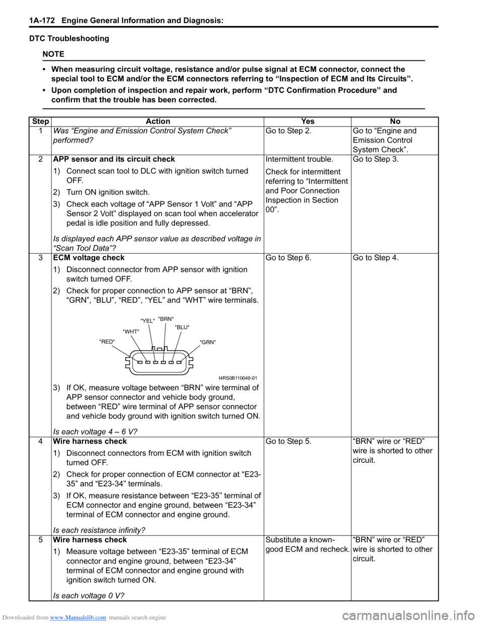
Downloaded from www.Manualslib.com manuals search engine 1A-172 Engine General Information and Diagnosis:
DTC Troubleshooting
NOTE
• When measuring circuit voltage, resistance and/or pulse signal at ECM connector, connect the
special tool to ECM and/or the ECM connectors re ferring to “Inspection of ECM and Its Circuits”.
• Upon completion of inspection and repair work, perform “DTC Confirmation Procedure” and confirm that the trouble has been corrected.
Step Action YesNo
1 Was “Engine and Emission Control System Check”
performed? Go to Step 2.
Go to “Engine and
Emission Control
System Check”.
2 APP sensor and its circuit check
1) Connect scan tool to DLC with ignition switch turned
OFF.
2) Turn ON ignition switch.
3) Check each voltage of “APP Sensor 1 Volt” and “APP Sensor 2 Volt” displayed on scan tool when accelerator
pedal is idle position and fully depressed.
Is displayed each APP sensor value as described voltage in
“Scan Tool Data”? Intermittent trouble.
Check for intermittent
referring to “Intermittent
and Poor Connection
Inspection in Section
00”.
Go to Step 3.
3 ECM voltage check
1) Disconnect connector from APP sensor with ignition
switch turned OFF.
2) Check for proper connection to APP sensor at “BRN”, “GRN”, “BLU”, “RED”, “YEL” and “WHT” wire terminals.
3) If OK, measure voltage between “BRN” wire terminal of APP sensor connector and vehicle body ground,
between “RED” wire terminal of APP sensor connector
and vehicle body ground with ignition switch turned ON.
Is each voltage 4 – 6 V? Go to Step 6.
Go to Step 4.
4 Wire harness check
1) Disconnect connectors from ECM with ignition switch
turned OFF.
2) Check for proper connection of ECM connector at “E23- 35” and “E23-34” terminals.
3) If OK, measure resistance between “E23-35” terminal of ECM connector and engine ground, between “E23-34”
terminal of ECM connector and engine ground.
Is each resistance infinity? Go to Step 5.
“BRN” wire or “RED”
wire is shorted to other
circuit.
5 Wire harness check
1) Measure voltage between “E23-35” terminal of ECM
connector and engine ground, between “E23-34”
terminal of ECM connector and engine ground with
ignition switch turned ON.
Is each voltage 0 V? Substitute a known-
good ECM and recheck.
“BRN” wire or “RED”
wire is shorted to other
circuit.
"GRN"
"BLU"
"BRN"
"YEL"
"WHT"
"RED"
I4RS0B110048-01
Page 227 of 1496
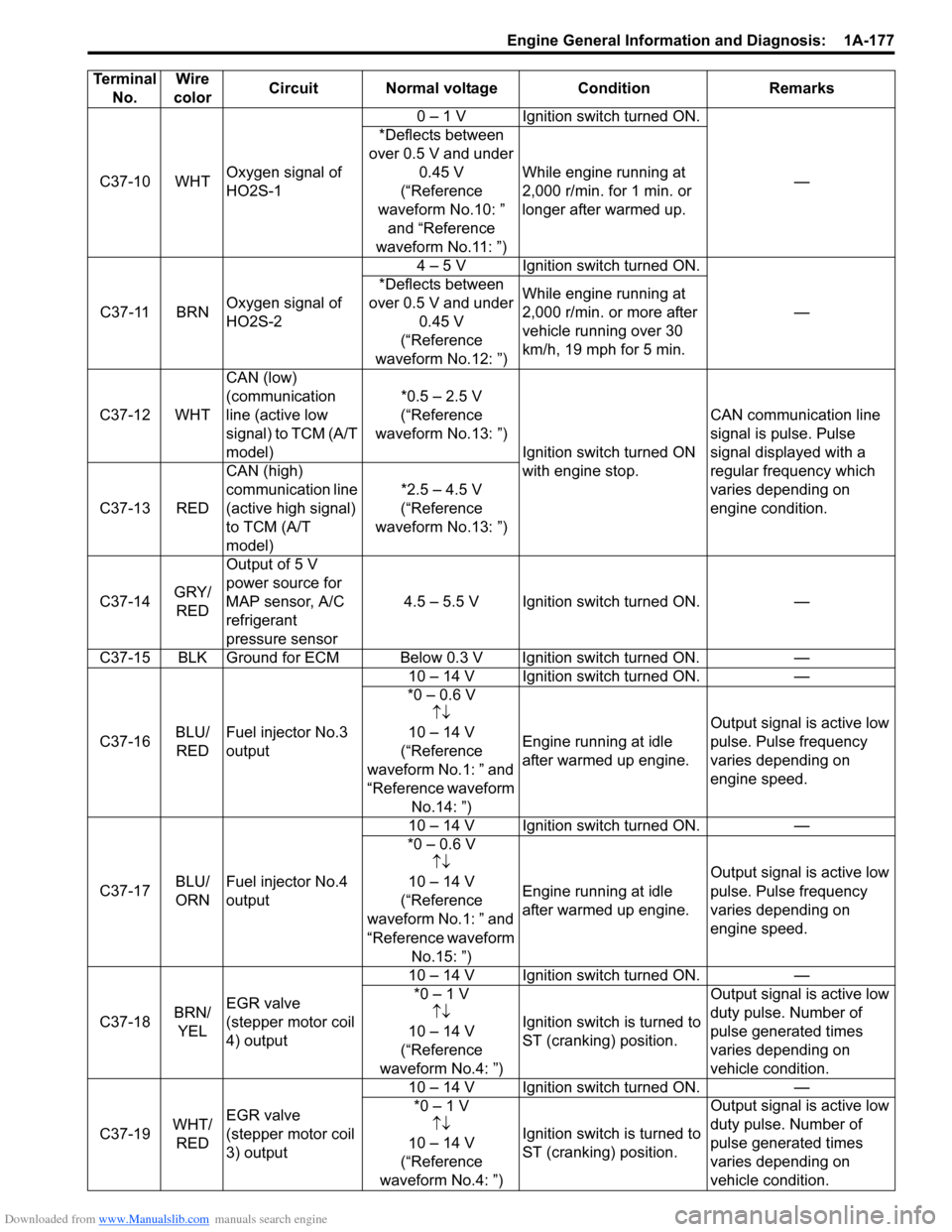
Downloaded from www.Manualslib.com manuals search engine Engine General Information and Diagnosis: 1A-177
C37-10 WHTOxygen signal of
HO2S-1 0 – 1 V Ignition switch turned ON.
—
*Deflects between
over 0.5 V and under 0.45 V
(“Reference
waveform No.10: ” and “Reference
waveform No.11: ”) While engine running at
2,000 r/min. for 1 min. or
longer after warmed up.
C37-11 BRN Oxygen signal of
HO2S-2 4 – 5 V Ignition switch turned ON.
—
*Deflects between
over 0.5 V and under 0.45 V
(“Reference
waveform No.12: ”) While engine running at
2,000 r/min. or more after
vehicle running over 30
km/h, 19 mph for 5 min.
C37-12 WHT CAN (low)
(communication
line (active low
signal) to TCM (A/T
model) *0.5 – 2.5 V
(“Reference
waveform No.13: ”) Ignition switch turned ON
with engine stop. CAN communication line
signal is pulse. Pulse
signal displayed with a
regular frequency which
varies depending on
engine condition.
C37-13 RED CAN (high)
communication line
(active high signal)
to TCM (A/T
model) *2.5 – 4.5 V
(“Reference
waveform No.13: ”)
C37-14 GRY/
RED Output of 5 V
power source for
MAP sensor, A/C
refrigerant
pressure sensor
4.5 – 5.5 V Ignition switch turned ON. —
C37-15 BLK Ground for ECM Below 0.3 V Ignition switch turned ON. —
C37-16 BLU/
RED Fuel injector No.3
output 10 – 14 V Ignition switch turned ON. —
*0 – 0.6 V ↑↓
10 – 14 V
(“Reference
waveform No.1: ” and
“Reference waveform No.14: ”) Engine running at idle
after warmed up engine.
Output signal is active low
pulse. Pulse frequency
varies depending on
engine speed.
C37-17 BLU/
ORNFuel injector No.4
output 10 – 14 V Ignition switch turned ON. —
*0 – 0.6 V ↑↓
10 – 14 V
(“Reference
waveform No.1: ” and
“Reference waveform No.15: ”) Engine running at idle
after warmed up engine.
Output signal is active low
pulse. Pulse frequency
varies depending on
engine speed.
C37-18 BRN/
YEL EGR valve
(stepper motor coil
4) output 10 – 14 V Ignition switch turned ON. —
*0 – 1 V ↑↓
10 – 14 V
(“Reference
waveform No.4: ”) Ignition switch is turned to
ST (cranking) position. Output signal is active low
duty pulse. Number of
pulse generated times
varies depending on
vehicle condition.
C37-19 WHT/
RED EGR valve
(stepper motor coil
3) output 10 – 14 V Ignition switch turned ON. —
*0 – 1 V ↑↓
1
0 – 14 V
(“Reference
waveform No.4: ”) Ignition switch is turned to
ST (cranking) position. Output signal is active low
duty pulse. Number of
pulse generated times
varies depending on
vehicle condition.
Terminal
No. Wire
color Circuit Normal voltage
ConditionRemarks
Page 230 of 1496
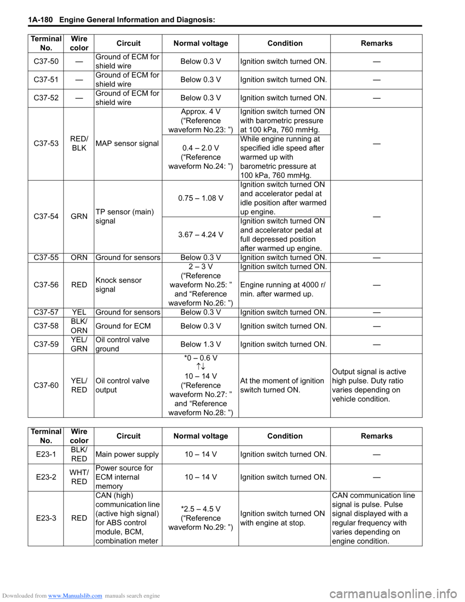
Downloaded from www.Manualslib.com manuals search engine 1A-180 Engine General Information and Diagnosis:
C37-50 —Ground of ECM for
shield wire Below 0.3 V Ignition switch turned ON. —
C37-51 — Ground of ECM for
shield wire Below 0.3 V Ignition switch turned ON. —
C37-52 — Ground of ECM for
shield wire Below 0.3 V Ignition switch turned ON. —
C37-53 RED/
BLK MAP sensor signal Approx. 4 V
(“Reference
waveform No.23: ”) Ignition switch turned ON
with barometric pressure
at 100 kPa, 760 mmHg.
—
0.4 – 2.0 V
(“Reference
waveform No.24: ”) While engine running at
specified idle speed after
warmed up with
barometric pressure at
100 kPa, 760 mmHg.
C37-54 GRN TP sensor (main)
signal 0.75 – 1.08 V
Ignition switch turned ON
and accelerator pedal at
idle position after warmed
up engine.
—
3.67 – 4.24 V Ignition switch turned ON
and accelerator pedal at
full depressed position
after warmed up engine.
C37-55 ORN Ground for sensors Below 0.3 V Ignition switch turned ON. —
C37-56 RED Knock sensor
signal 2 – 3 V
(“Reference
waveform No.25: ” and “Reference
waveform No.26: ”) Ignition switch turned ON.
—
Engine running at 4000 r/
min. after warmed up.
C37-57 YEL Ground for sensors Below 0.3 V Ignition switch turned ON. —
C37-58 BLK/
ORN Ground for ECM Below 0.3 V Ignition switch turned ON.
—
C37-59 YEL/
GRN Oil control valve
ground
Below 1.3 V Ignition switch turned ON.
—
C37-60 YEL/
RED Oil control valve
output *0 – 0.6 V
↑↓
10 – 14 V
(“Reference
waveform No.27: ” and “Reference
waveform No.28: ”) At the moment of ignition
switch turned ON.
Output signal is active
high pulse. Duty ratio
varies depending on
vehicle condition.
Terminal
No. Wire
color Circuit Normal voltage
ConditionRemarks
Terminal
No. Wire
color Circuit Normal voltage Condition Remarks
E23-1 BLK/
RED Main power supply 10 – 14 V Ignition switch turned ON. —
E23-2 WHT/
RED Power source for
ECM internal
memory
10 – 14 V Ignition switch turned ON. —
E23-3 RED CAN (high)
communication line
(active high signal)
for ABS control
module, BCM,
combination meter *2.5 – 4.5 V
(“Reference
waveform No.29: ”) Ignition switch turned ON
with engine at stop. CAN communication line
signal is pulse. Pulse
signal displayed with a
regular frequency with
varies depending on
engine condition.
Page 231 of 1496
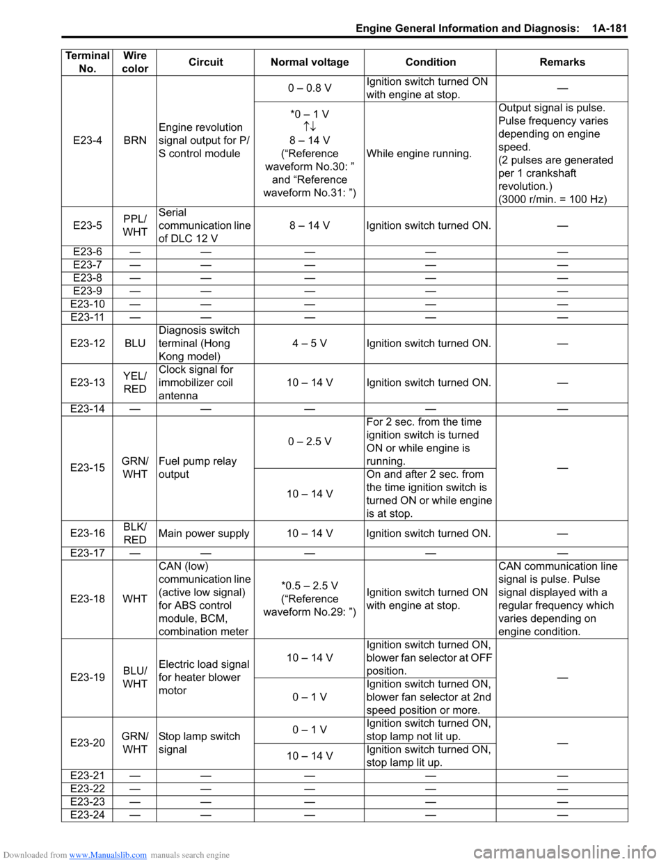
Downloaded from www.Manualslib.com manuals search engine Engine General Information and Diagnosis: 1A-181
E23-4 BRNEngine revolution
signal output for P/
S control module 0 – 0.8 V
Ignition switch turned ON
with engine at stop. —
*0 – 1 V ↑↓
8 – 14 V
(“Reference
waveform No.30: ” and “Reference
waveform No.31: ”) While engine running. Output signal is pulse.
Pulse frequency varies
depending on engine
speed.
(2 pulses are generated
per 1 crankshaft
revolution.)
(3000 r/min. = 100 Hz)
E23-5 PPL/
WHT Serial
communication line
of DLC 12 V
8 – 14 V Ignition switch turned ON. —
E23-6 — — — — —
E23-7 — — — — —
E23-8 — — — — —
E23-9 — — — — —
E23-10 — — — — — E23-11 — — — — —
E23-12 BLU Diagnosis switch
terminal (Hong
Kong model) 4 – 5 V Ignition switch turned ON. —
E23-13 YEL/
RED Clock signal for
immobilizer coil
antenna
10 – 14 V Ignition switch turned ON. —
E23-14 — — — — —
E23-15 GRN/
WHT Fuel pump relay
output 0 – 2.5 V
For 2 sec. from the time
ignition switch is turned
ON or while engine is
running.
—
10 – 14 V On and after 2 sec. from
the time ignition switch is
turned ON or while engine
is at stop.
E23-16 BLK/
RED Main power supply 10 – 14 V Ignition switch turned ON. —
E23-17 — — — — —
E23-18 WHT CAN (low)
communication line
(active low signal)
for ABS control
module, BCM,
combination meter *0.5 – 2.5 V
(“Reference
waveform No.29: ”) Ignition switch turned ON
with engine at stop. CAN communication line
signal is pulse. Pulse
signal displayed with a
regular frequency which
varies depending on
engine condition.
E23-19 BLU/
WHT Electric load signal
for heater blower
motor 10 – 14 V
Ignition switch turned ON,
blower fan selector at OFF
position.
—
0 – 1 V Ignition switch turned ON,
blower fan selector at 2nd
speed position or more.
E23-20 GRN/
WHT Stop lamp switch
signal 0 – 1 V
Ignition switch turned ON,
stop lamp not lit up.
—
10 – 14 V Ignition switch turned ON,
stop lamp lit up.
E23-21 — — — — —
E23-22 — — — — —
E23-23 — — — — —
E23-24 — — — — —
Terminal
No. Wire
color Circuit Normal voltage Condition Remarks
Page 256 of 1496
Downloaded from www.Manualslib.com manuals search engine 1A-206 Engine General Information and Diagnosis:
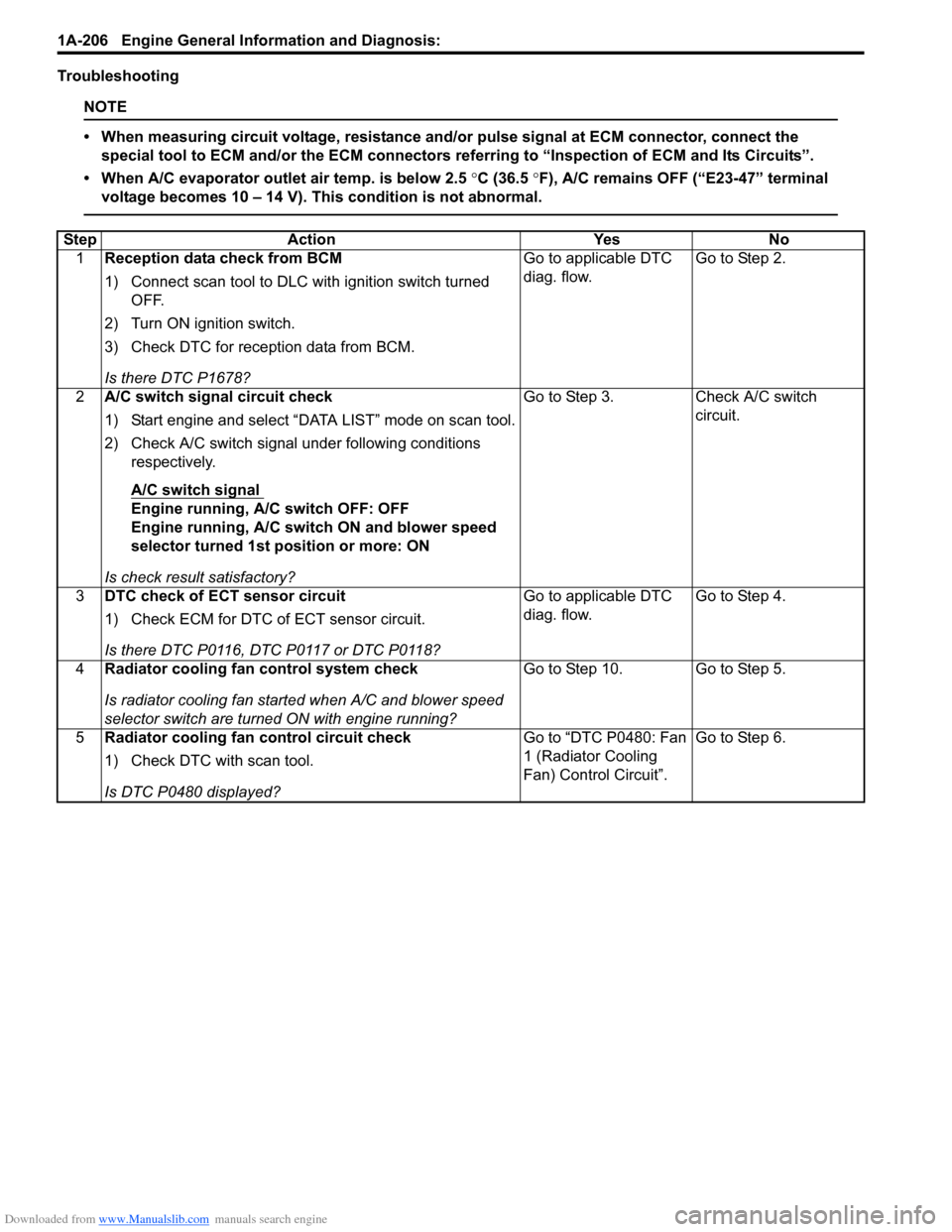
Troubleshooting
NOTE
• When measuring circuit voltage, resistance and/or pulse signal at ECM connector, connect the
special tool to ECM and/or the ECM connectors re ferring to “Inspection of ECM and Its Circuits”.
• When A/C evaporator outlet air temp. is below 2.5 °C (36.5 °F), A/C remains OFF (“E23-47” terminal
voltage becomes 10 – 14 V). This condition is not abnormal.
Step Action YesNo
1 Reception data check from BCM
1) Connect scan tool to DLC with ignition switch turned
OFF.
2) Turn ON ignition switch.
3) Check DTC for reception data from BCM.
Is there DTC P1678? Go to applicable DTC
diag. flow.
Go to Step 2.
2 A/C switch signal circuit check
1) Start engine and select “DATA LIST” mode on scan tool.
2) Check A/C switch signal under following conditions
respectively.
A/C switch signal
Engine running, A/C switch OFF: OFF
Engine running, A/C switch ON and blower speed
selector turned 1st position or more: ON
Is check result satisfactory? Go to Step 3. Check A/C switch
circuit.
3 DTC check of ECT sensor circuit
1) Check ECM for DTC of ECT sensor circuit.
Is there DTC P0116, DTC P0117 or DTC P0118? Go to applicable DTC
diag. flow.
Go to Step 4.
4 Radiator cooling fan control system check
Is radiator cooling fan started when A/C and blower speed
selector switch are turned ON with engine running? Go to Step 10. Go to Step 5.
5 Radiator cooling fan control circuit check
1) Check DTC with scan tool.
Is DTC P0480 displayed? Go to “DTC P0480: Fan
1 (Radiator Cooling
Fan) Control Circuit”.
Go to Step 6.
Page 268 of 1496
Downloaded from www.Manualslib.com manuals search engine 1B-1 Aux. Emission Control Devices:
Engine
Aux. Emission Control Devices
Diagnostic Information and Procedures
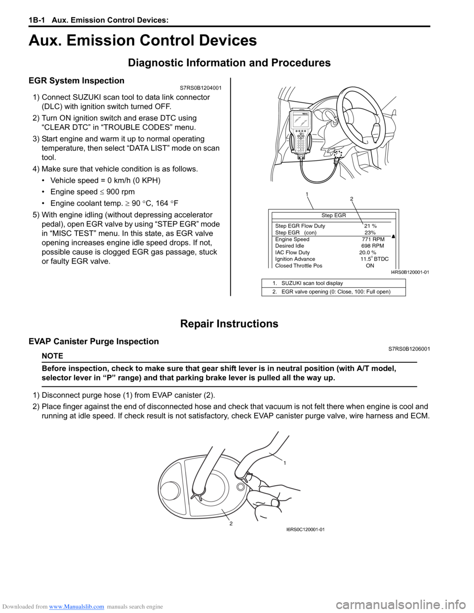
EGR System InspectionS7RS0B1204001
1) Connect SUZUKI scan tool to data link connector (DLC) with ignition switch turned OFF.
2) Turn ON ignition switch and erase DTC using “CLEAR DTC” in “TROUBLE CODES” menu.
3) Start engine and warm it up to normal operating temperature, then select “DATA LIST” mode on scan
tool.
4) Make sure that vehicle condition is as follows.
• Vehicle speed = 0 km/h (0 KPH)
• Engine speed ≤ 900 rpm
• Engine coolant temp. ≥ 90 °C, 164 °F
5) With engine idling (without depressing accelerator pedal), open EGR valve by using “STEP EGR” mode
in “MISC TEST” menu. In this state, as EGR valve
opening increases engine idle speed drops. If not,
possible cause is clogged EGR gas passage, stuck
or faulty EGR valve.
Repair Instructions
EVAP Canister Purge InspectionS7RS0B1206001
NOTE
Before inspection, check to make sure that gear shift lever is in neutral position (with A/T model,
selector lever in “P” range) and that parking brake lever is pulled all the way up.
1) Disconnect purge hose (1) from EVAP canister (2).
2) Place finger against the end of disconne cted hose and check that vacuum is not felt there when engine is cool and
running at idle speed. If check result is not satisfacto ry, check EVAP canister purge valve, wire harness and ECM.
1. SUZUKI scan tool display
2. EGR valve opening (0: Close, 100: Full open)
Step EGR
Step EGR Flow Duty 21 %
Step EGR (con) 23%
Engine Speed 771 RPM
Desired Idle 698 RPM
IAC Flow Duty 20.0 %
Ignition Advance 11.5 BTDC
Closed Throttle Pos ON
1 2
I4RS0B120001-01
1
2
I6RS0C120001-01
Page 645 of 1496
Downloaded from www.Manualslib.com manuals search engine Automatic Transmission/Transaxle: 5A-1
Transmission / Transaxle
Automatic Transmission/Transaxle
Precautions
Precautions in Diagnosing TroubleS7RS0B5100001
• Do not disconnect couplers from TCM, battery cable from battery, TCM ground wire harness from engine or
main fuse before checking the diagnostic information
(DTC, freeze frame data, etc.) stored in TCM memory.
Such disconnection will clea r memorized information
in TCM memory.
• Diagnostic information stored in TCM memory can be cleared as well as checked by using SUZUKI scan
tool or generic scan tool. Before using scan tool, read
its Operator’s (Instruction) Manual carefully to have
good understanding as to what functions are available
and how to use it.
It is indistinguishable wh ich module turns on MIL
because not only ECM but also TCM turns on MIL.
Therefore, check both ECM and TCM for DTC when
MIL lights on.
When checking TCM for DTC, keep in mind that DTC
is displayed on the scan tool as follows depending on
the scan tool used.
– SUZUKI scan tool displays DTC detected by TCM.
– Generic scan tool displays DTC detected by each of ECM and TCM simultaneously.
• Using SUZUKI scan tool the diagnostic information stored in TCM memory can be checked and cleared
as well. Before its use, be sure to read Operator’s
Manual supplied with it carefully to have good
understanding of its functions and usage.
• Be sure to read “Precautions for Electrical Circuit Service in Section 00” befo re inspection and observe
what is written there.
• TCM replacement
– When substituting a known-good TCM, check that all relays and actuators have resistance of
specified value.
Neglecting this check may result in damage to good
TCM.
• Communication of ECUs , ECM, TCM, ABS control
module, keyless start control module and BCM is
established by CAN (Controller Area Network).
Therefore, handle CAN communication line with care
referring to “Precaution for CAN Communication
System in Section 00”.
Precautions for Disassembly and ReassemblyS7RS0B5100002
When repairing automatic transaxle, it is necessary to
conduct the on-vehicle test to investigate where the
cause of the trouble lies first.
Then whether overhaul should be done or not is
determined. If the transaxle is disassembled without
such preliminary procedure, not only the cause of the
trouble would be unknown, but also a secondary trouble
may occur and often time would be wasted.
As the automatic transaxle consists of high precision
component, the following cautions should be strictly
observed when handling its parts in disassembly and
reassembly.
• Disassembling valve body assembly is prohibited
essentially. However, a few parts can be
disassembled. When disassembling valve body
component parts, confirm whether their parts are
allowed to disassemble or not referring to “Valve Body
Assembly Disassembly and Reassembly”.
• When component part of forward clutch, direct clutch, 2nd brake and/or O/D and 2nd coast brake, namely
clutch disc, brake disc, retaining plate and/or
separator plate, have been replaced, all learned
contents, which have been stored in TCM memory by
executing learning control, should be initialized
referring to “Learning Control Initialization”.
• Make sure to wash dirt off from the transaxle so that no such dirt will enter the transaxle during
dismounting and remounting.
• Select a clean place free from dust and dirt for overhauling.
• Place a rubber mat on the work bench to protect parts from damage.
• Work gloves or shop cloth should not be used. (Use a nylon cloth or a paper towel.)
• When separating the case joint, do not pry with a screwdriver or such but tap with a plastic hammer
lightly.
• Make sure to wash dirt off from the transaxle so that no such dirt will enter the transaxle during
disassembly and reassembly.
• Wash the disassembled parts in ATF (Automatic Transaxle Fluid) or kerosene (using care not to allow
ATF or kerosene to get on your face, etc.) and confirm
that each fluid passage is not clogged by blowing air
into it. But use kerosene to wash the discs, resin
washers and rubber parts.
• Replace each gasket, oil seal and O-ring with a new one.
• Apply ATF to sliding or rotating parts before
reassembly.
Page 982 of 1496
Downloaded from www.Manualslib.com manuals search engine 7B-34 Air Conditioning System: Automatic Type
Automatic Type
Precautions
A/C System CautionS7RS0B7220001
Refer to “A/C System Caution”.
Precautions in Diagnosing TroubleS7RS0B7220002
• Do not disconnect couplers from HVAC control module, battery cable from battery, HVAC control module ground
wire harness from body or main fuse before confirming diagnostic information (diagnostic trouble code) stored in
HVAC control module memory.
• Diagnostic information (diagnostic trouble code) stored in HVAC control module can be checked by display of HVAC
control module. Also, it can be checked by using SU ZUKI scan tool. Before checking diagnostic information
(diagnostic trouble code), read this manual and operator's manual for SUZUKI scan tool to know how to read
diagnostic information (diagnostic trouble code).
• When trouble is diagnosed using diagnostic information (diagnostic trouble code) on display of HVAC control
module, keep in your mind that each diagnostic inform ation (diagnostic trouble code) has priority, and only
diagnostic information (diagnostic troub le code) which has the highest priority is indicated. Therefore, after
troubleshooting the malfunction, make sure if there exists any other diagnostic information (diagnostic trouble
code).
• Be sure to read “Precautions for Electrical Circuit Service in Section 00” before inspection.
Precautions on Servicing A/C SystemS7RS0B7220003
Refer to “Precautions on Servicing A/C System”.
General Description
Auto A/C System DescriptionS7RS0B7221001
The automatic type air conditioning system (auto A/C) is pr ovided with the function to automatically control the inside
air temperature, fan speed, air flow outl et direction and air intake position by HVAC control module in addition to
functions of the manual type air conditioning system (manua l A/C). Once the inside air temperature is set using the
temperature selector, HVAC control module automatically controls the inside air temperature at the constant level at all
times based on the inside air temperature, outside ai r temperature, amount of sunlight and engine coolant
temperature detected respectively by the inside air te mperature sensor, outside air temperature sensor, sunload
sensor and ECT sensor. At this time, “FULL AUTO A/ C” appears on the display of HVAC control module.
With the air intake selector pushed in the above state, it is possible to select any position of the air intake actuator.
Then, “FULL AUTO A/C” on the display changes to “AUTO A/C”.
Page 987 of 1496
Downloaded from www.Manualslib.com manuals search engine Air Conditioning System: Automatic Type 7B-39
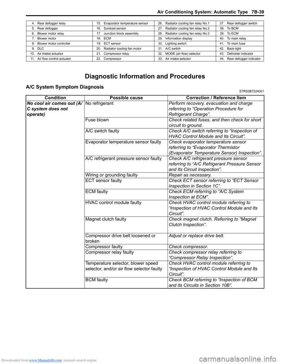
Diagnostic Information and Procedures
A/C System Symptom DiagnosisS7RS0B7224001
4. Rear defogger relay 15. Evaporator temperature sensor 26. Radiator cooling fan relay No.1 37. Rear defogger switch
5. Rear defogger 16. Sunload sensor 27. Radiator cooling fan relay No.2 38. To BCM
6. Blower motor relay 17. Junction block assembly 28. Radiator cooling fan relay No.3 39. To ECM
7. Blower motor 18. ECM 29. Information display 40. To main relay
8. Blower motor controller 19. ECT sensor 30. Lighting switch 41. To main fuse
9. DLC 20. Radiator cooling fan motor 31. A/C switch 42. Back-light
10. Air intake actuator 21. Compressor relay 32. MODE (air flow) selector 43. Defroster indicator 11. Air flow control actuator 22. Compressor 33. Air intake selector 44. Rear defogger indicator
Condition Possible cause Correction / Reference Item
No cool air comes out (A/
C system does not
operate) No refrigerant
Perform recovery, evacuation and charge
referring to “Operation Procedure for
Refrigerant Charge”.
Fuse blown Check related fuses, and then check for short
circuit to ground.
A/C switch faulty Check A/C switch referring to “Inspection of
HVAC Control Module and Its Circuit”.
Evaporator temperature sensor faulty Check evaporator temperature sensor
referring to “Evaporator Thermistor
(Evaporator Temperature Sensor) Inspection”.
A/C refrigerant pressure sensor faulty Check A/C refrigerant pressure sensor
referring to “A/C Refrigerant Pressure Sensor
and Its Circuit Inspection”.
Wiring or grounding faulty Repair as necessary.
ECT sensor faulty Check ECT sensor referring to “ECT Sensor
Inspection in Section 1C”.
ECM faulty Check ECM referring to “A/C System
Inspection at ECM”.
HVAC control module faulty Check HVAC control module referring to
“Inspection of HVAC Control Module and Its
Circuit”.
Magnet clutch faulty Check magnet clutch. Referring to “Magnet
Clutch Inspection”.
Compressor drive belt loosened or
broken Adjust or replace drive belt.
Compressor faulty Check compressor.
Compressor relay faulty Check compressor relay referring to
“Compressor Relay Inspection”.
Temperature selector, blower speed
selector, and/or air flow selector faulty Check HVAC control module referring to
“Inspection of HVAC Control Module and Its
Circuit”.
BCM faulty Check BCM referring to “Inspection of BCM
and its Circuits in Section 10B”.
Page 1011 of 1496
Downloaded from www.Manualslib.com manuals search engine Air Conditioning System: Automatic Type 7B-63
DTC B1546: A/C Refrigerant Pressure MalfunctionS7RS0B7224018
DTC Detecting Condition and Trouble Area
DTC Troubleshooting
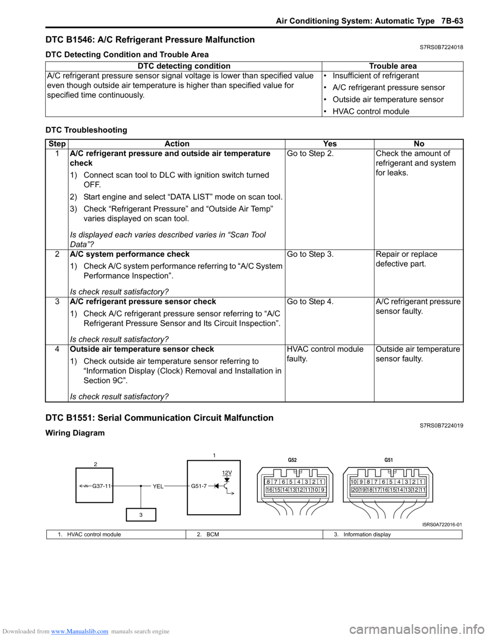
DTC B1551: Serial Communication Circuit MalfunctionS7RS0B7224019
Wiring DiagramDTC detecting condition Trouble area
A/C refrigerant pressure sensor signal voltage is lower t han specified value
even though outside air temperature is higher than specified value for
specified time continuously. • Insufficient of refrigerant
• A/C refrigerant pressure sensor
• Outside air temperature sensor
• HVAC control module
Step
Action YesNo
1 A/C refrigerant pressure and outside air temperature
check
1) Connect scan tool to DLC with ignition switch turned
OFF.
2) Start engine and select “DATA LIST” mode on scan tool.
3) Check “Refrigerant Pressure” and “Outside Air Temp” varies displayed on scan tool.
Is displayed each va ries described varies in “Scan Tool
Data”? Go to Step 2.
Check the amount of
refrigerant and system
for leaks.
2 A/C system performance check
1) Check A/C system performance referring to “A/C System
Performance Inspection”.
Is check result satisfactory? Go to Step 3.
Repair or replace
defective part.
3 A/C refrigerant pressure sensor check
1) Check A/C refrigerant pressure sensor referring to “A/C
Refrigerant Pressure Sensor and Its Circuit Inspection”.
Is check result satisfactory? Go to Step 4.
A/C refrigerant pressure
sensor faulty.
4 Outside air temperature sensor check
1) Check outside air temperature sensor referring to
“Information Display (Clock) Removal and Installation in
Section 9C”.
Is check result satisfactory? HVAC control module
faulty.
Outside air temperature
sensor faulty.
YEL17812910
65 431516 14 13 12 11
G52
789101920121112
65 431718 16 15 14 13
G51
G51-7
12V
2
3
G37-11
I5RS0A722016-01
1. HVAC control module 2. BCM3. Information display