oil change SUZUKI SWIFT 2005 2.G Service Owner's Guide
[x] Cancel search | Manufacturer: SUZUKI, Model Year: 2005, Model line: SWIFT, Model: SUZUKI SWIFT 2005 2.GPages: 1496, PDF Size: 34.44 MB
Page 817 of 1496
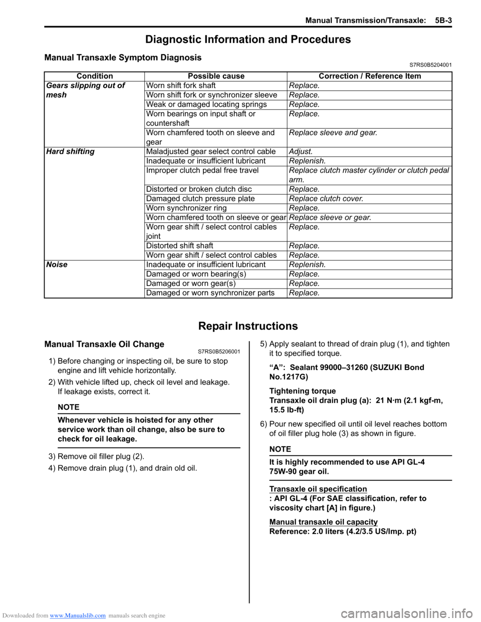
Downloaded from www.Manualslib.com manuals search engine Manual Transmission/Transaxle: 5B-3
Diagnostic Information and Procedures
Manual Transaxle Symptom DiagnosisS7RS0B5204001
Repair Instructions
Manual Transaxle Oil ChangeS7RS0B5206001
1) Before changing or inspecting oil, be sure to stop engine and lift vehicle horizontally.
2) With vehicle lifted up, check oil level and leakage. If leakage exists, correct it.
NOTE
Whenever vehicle is hoisted for any other
service work than oil change, also be sure to
check for oil leakage.
3) Remove oil filler plug (2).
4) Remove drain plug (1), and drain old oil. 5) Apply sealant to thread of drain plug (1), and tighten
it to specified torque.
“A”: Sealant 99000–31260 (SUZUKI Bond
No.1217G)
Tightening torque
Transaxle oil drain plug (a): 21 N·m (2.1 kgf-m,
15.5 lb-ft)
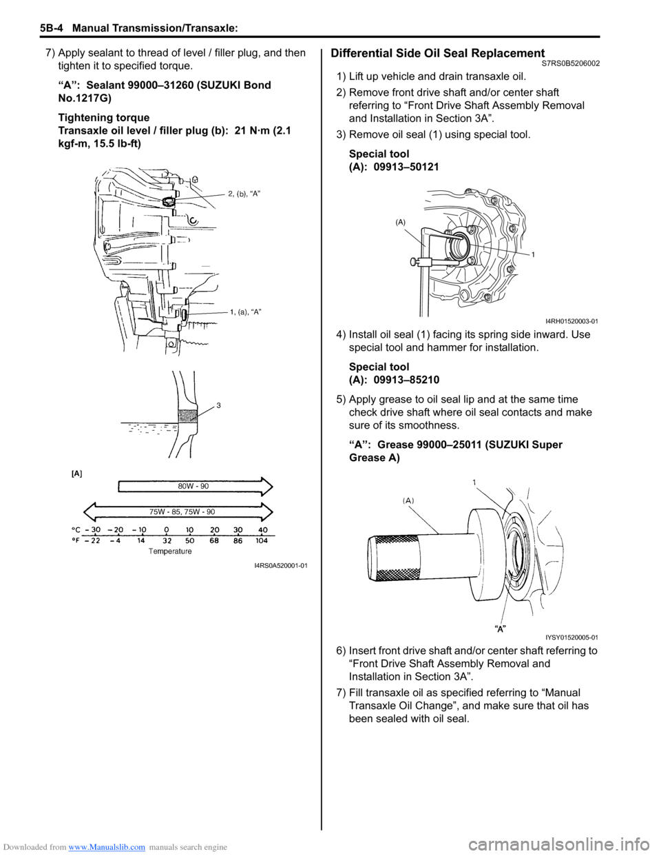
6) Pour new specified oil unt il oil level reaches bottom
of oil filler plug hole (3) as shown in figure.NOTE
It is highly recommended to use API GL-4
75W-90 gear oil.
Transaxle oil specification
: API GL-4 (For SAE classification, refer to
viscosity chart [A] in figure.)
Manual transaxle oil capacity
Reference: 2.0 liters (4.2/3.5 US/Imp. pt)
Condition Possible cause Correction / Reference Item
Gears slipping out of
mesh Worn shift fork shaft
Replace.
Worn shift fork or synchronizer sleeve Replace.
Weak or damaged locating springs Replace.
Worn bearings on input shaft or
countershaft Replace.
Worn chamfered tooth on sleeve and
gear Replace sleeve and gear.
Hard shifting Maladjusted gear select control cable Adjust.
Inadequate or insufficient lubricant Replenish.
Improper clutch pedal free travel Replace clutch master cylinder or clutch pedal
arm.
Distorted or broken clutch disc Replace.
Damaged clutch pressure plate Replace clutch cover.
Worn synchronizer ring Replace.
Worn chamfered tooth on sleeve or gear Replace sleeve or gear.
Worn gear shift / select control cables
joint Replace.
Distorted shift shaft Replace.
Worn gear shift / select control cables Replace.
Noise Inadequate or insufficient lubricant Replenish.
Damaged or worn bearing(s) Replace.
Damaged or worn gear(s) Replace.
Damaged or worn synchronizer parts Replace.
Page 818 of 1496
Downloaded from www.Manualslib.com manuals search engine 5B-4 Manual Transmission/Transaxle:
7) Apply sealant to thread of level / filler plug, and then
tighten it to specified torque.
“A”: Sealant 99000–31260 (SUZUKI Bond
No.1217G)
Tightening torque
Transaxle oil level / filler plug (b): 21 N·m (2.1
kgf-m, 15.5 lb-ft)Differential Side Oil Seal ReplacementS7RS0B5206002
1) Lift up vehicle and drain transaxle oil.
2) Remove front drive shaft and/or center shaft referring to “Front Driv e Shaft Assembly Removal
and Installation in Section 3A”.
3) Remove oil seal (1) using special tool.
Special tool
(A): 09913–50121
4) Install oil seal (1) facing its spring side inward. Use special tool and hammer for installation.
Special tool
(A): 09913–85210
5) Apply grease to oil seal lip and at the same time check drive shaft where oil seal contacts and make
sure of its smoothness.
“A”: Grease 99000–25011 (SUZUKI Super
Grease A)
6) Insert front drive shaft and/or center shaft referring to “Front Drive Shaft A ssembly Removal and
Installation in Section 3A”.
7) Fill transaxle oil as specified referring to “Manual Transaxle Oil Change”, and make sure that oil has
been sealed with oil seal.
I4RS0A520001-01
(A)
1
I4RH01520003-01
IYSY01520005-01
Page 824 of 1496
Downloaded from www.Manualslib.com manuals search engine 5B-10 Manual Transmission/Transaxle:
16) Remove engine under covers.
17) Support transaxle with transmission jack.
18) Remove transaxle to engine bolts and nut of lower side.
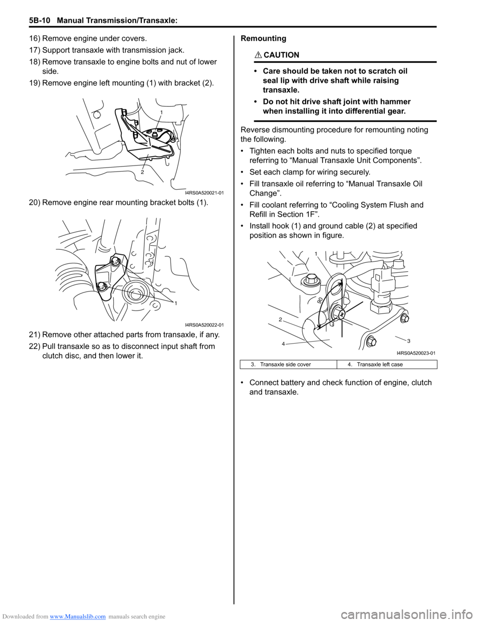
19) Remove engine left mounting (1) with bracket (2).
20) Remove engine rear mounting bracket bolts (1).
21) Remove other attached parts from transaxle, if any.
22) Pull transaxle so as to disconnect input shaft from clutch disc, and then lower it. Remounting
CAUTION!
• Care should be taken not to scratch oil
seal lip with drive shaft while raising
transaxle.
• Do not hit drive shaft joint with hammer when installing it into differential gear.
Reverse dismounting procedure for remounting noting
the following.
• Tighten each bolts and nuts to specified torque referring to “Manual Transaxle Unit Components”.
• Set each clamp for wiring securely.
• Fill transaxle oil referring to “Manual Transaxle Oil
Change”.
• Fill coolant referring to “Cooling System Flush and
Refill in Section 1F”.
• Install hook (1) and ground cable (2) at specified position as shown in figure.
• Connect battery and check function of engine, clutch
and transaxle.
1
2
I4RS0A520021-01
1
I4RS0A520022-01
3. Transaxle side cover 4. Transaxle left case
90
1
2 3
4
I4RS0A520023-01
Page 949 of 1496
Downloaded from www.Manualslib.com manuals search engine Air Conditioning System: Manual Type 7B-1
HVAC
Air Conditioning System
Manual Type
Precautions
A/C System CautionS7RS0B7210001
CAUTION!
• The air conditioning system of this vehicle uses refrigerant HFC-134a (R-134a).
None of refrigerant, compressor oil and component parts is interchangeable between two types of
A/C: one using refrigerant HFC-134a (R-134a) and the other using refrigerant CFC-12 (R-12).
Be sure to check which refrigerant is used be fore any service work including inspection and
maintenance. For identification between these two types, refer to “Refrigerant Type Identification”.
When replenishing or changing refrigerant and comp ressor oil and when replacing parts, make sure
that the material or the part to be used is appropriate to the A/C installed in the vehicle being
serviced.
Use of incorrect one will result in leakage of refrigerant, damage in parts or other faulty condition.
• When servicing the compressor, keep dirt or foreign material away from getting on or into the compressor parts and system. Clean tools and a clean work area are important for proper service.
The compressor connection and the outside of the compressor should be cleaned before any “On
vehicle” repair or before removal of the compressor. The parts must be kept clean at all times and
any parts to be reassembled should be cleaned with trichloromethane, naphtha, kerosene or
equivalent solvent and dried with dry air. Use only lint free cloths to wipe parts.
• When compressor is removed from the vehicle for servicing, the oil remaining in the compressor
should be discarded and new refrigerant oil added to the compressor.
Minor repair procedures may be done on the vehicle without discharging the system. Major repair
procedures require that the system be discharged of refrigerant.
Precautions on Servicing A/C SystemS7RS0B7210002
WARNING!
Should refrigerant HFC-134a (R-134a) is exposed to your eye(s), consult a doctor immediately.
• Do not use your hand to rub affected eye(s). Instead, use fresh cold water to splash it over affected area to thus gradually raise its temperature above the freezing point.
• Obtain proper treatment as soon as possible from a doctor or eye specialist. Should liquid refrigerant HFC-134a (R-134a) is exposed to your skin, such affected part should be treated in the
same manner as when skin is frostbitten or frozen.
Handling Refrigerant HFC-134a (R-134a)
• Always wear goggles to protect your eyes.
• Avoid direct contact to liquid refrigerant.
• Do not heat refrigerant container higher than 40 °C (104 ° F).
• Do not discharge refrigerant into atmosphere.
• Do not expose bright metals to liquid refrigerant. Refrig erant combined with moisture is corrosive and tarnishes
surfaces of bright metals including chrome.
Page 966 of 1496
Downloaded from www.Manualslib.com manuals search engine 7B-18 Air Conditioning System: Manual Type
When replacing other parts
Replenish the following amount of oil to compressor.
Amount of compressor oil to be replenished
Evaporator: 25 cm3 (25 ml, 0.85 US. oz, 0.88 Imp. oz)
Condenser: 15 cm3 (15 ml, 0.51 US. oz, 0.53 Imp. oz)
Receiver/dryer: 10 cm3 (10 ml, 0.34 US. oz, 0.35 lmp.
oz)
Hoses: 10 cm
3 (10 ml, 0.34 US. oz, 0.35 Imp. oz) each
Pipes: 10 cm3 (10 ml, 0.34 US. oz, 0.35 Imp. oz) each
Evacuation
CAUTION!
Do not evacuate before recovering
refrigerant in A/C system.
NOTE
Once air conditioning system circuit is
opened (exposed) to atmospheric air, system
must be evacuated by using a vacuum pump.
The A/C system should be attached with a
manifold gauge set, and should be evacuated
for approximately 15 minutes.
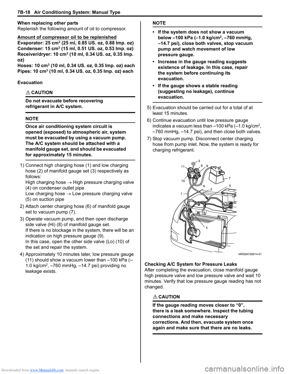
1) Connect high charging hose (1) and low charging hose (2) of manifold gauge set (3) respectively as
follows:
High charging hose → High pressure charging valve
(4) on condenser outlet pipe
Low charging hose → Low pressure charging valve
(5) on suction pipe
2) Attach center charging hose (6) of manifold gauge set to vacuum pump (7).
3) Operate vacuum pump, and then open discharge
side valve (Hi) (8) of manifold gauge set.
If there is no blockage in the system, there will be an
indication on high pressure gauge (9).
In this case, open the other side valve (Lo) (10) of
the set and repair the system.
4) Approximately 10 minutes later, low pressure gauge (11) should show a vacuum lower than –100 kPa (–
1.0 kg/cm
2, –760 mmHg, –14.7 psi) providing no
leakage exists.
NOTE
• If the system does not show a vacuum below –100 kPa (–1.0 kg/cm
2, –760 mmHg,
–14.7 psi), close both valves, stop vacuum
pump and watch movement of low
pressure gauge.
• Increase in the gauge reading suggests existence of leakage. In this case, repair
the system before continuing its
evacuation.
• If the gauge shows a stable reading (suggesting no leakage), continue
evacuation.
5) Evacuation should be carried out for a total of at least 15 minutes.
6) Continue evacuation until low pressure gauge indicates a vacuum less than –100 kPa (–1.0 kg/cm
2,
–760 mmHg, –14.7 psi), and then close both valves.
7) Stop vacuum pump. Disconnect center charging hose from pump inlet. No w, the system is ready for
charging refrigerant.
Checking A/C System for Pressure Leaks
After completing the evacuation, close manifold gauge
high pressure valve and low pressure valve and wait 10
minutes. Verify that low pressure gauge reading has not
changed.
CAUTION!
If the gauge reading moves closer to “0”,
there is a leak somewhere. Inspect the tubing
connections and make necessary
corrections. And then, evacuate system once
again and make sure that there are no leaks.
7 5
2
4
1
10
11
3
9 8
6
I4RS0A720014-01
Page 1308 of 1496
Downloaded from www.Manualslib.com manuals search engine 9C-13 Instrumentation / Driver Info. / Horn:
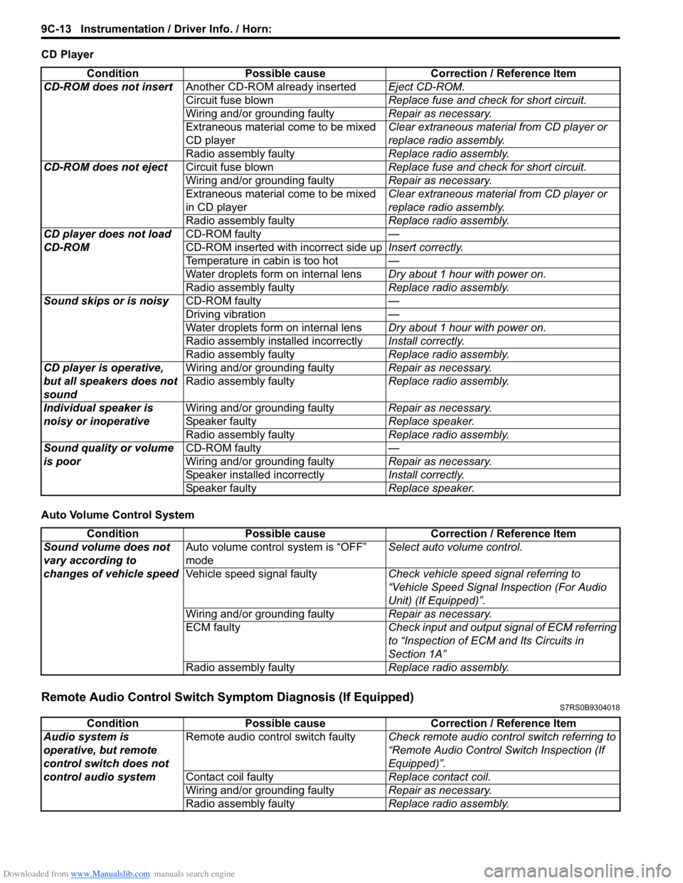
CD Player
Auto Volume Control System
Remote Audio Control Switch Symptom Diagnosis (If Equipped)S7RS0B9304018
ConditionPossible cause Correction / Reference Item
CD-ROM does not insert Another CD-ROM already inserted Eject CD-ROM.
Circuit fuse blown Replace fuse and check for short circuit.
Wiring and/or grounding faulty Repair as necessary.
Extraneous material come to be mixed
CD player Clear extraneous material from CD player or
replace radio assembly.
Radio assembly faulty Replace radio assembly.
CD-ROM does not eject Circuit fuse blown Replace fuse and check for short circuit.
Wiring and/or grounding faulty Repair as necessary.
Extraneous material come to be mixed
in CD player Clear extraneous material from CD player or
replace radio assembly.
Radio assembly faulty Replace radio assembly.
CD player does not load
CD-ROM CD-ROM faulty
—
CD-ROM inserted wit h incorrect side upInsert correctly.
Temperature in cabin is too hot —
Water droplets form on internal lens Dry about 1 hour with power on.
Radio assembly faulty Replace radio assembly.
Sound skips or is noisy CD-ROM faulty —
Driving vibration —
Water droplets form on internal lens Dry about 1 hour with power on.
Radio assembly installed incorrectly Install correctly.
Radio assembly faulty Replace radio assembly.
CD player is operative,
but all speakers does not
sound Wiring and/or grounding faulty
Repair as necessary.
Radio assembly faulty Replace radio assembly.
Individual speaker is
noisy or inoperative Wiring and/or grounding faulty
Repair as necessary.
Speaker faulty Replace speaker.
Radio assembly faulty Replace radio assembly.
Sound quality or volume
is poor CD-ROM faulty
—
Wiring and/or grounding faulty Repair as necessary.
Speaker installed incorrectly Install correctly.
Speaker faulty Replace speaker.
ConditionPossible cause Correction / Reference Item
Sound volume does not
vary according to
changes of vehicle speed Auto volume control system is “OFF”
mode
Select auto volume control.
Vehicle speed signal faulty Check vehicle speed signal referring to
“Vehicle Speed Signal Inspection (For Audio
Unit) (If Equipped)”.
Wiring and/or grounding faulty Repair as necessary.
ECM faulty Check input and output signal of ECM referring
to “Inspection of ECM and Its Circuits in
Section 1A”
Radio assembly faulty Replace radio assembly.
ConditionPossible cause Correction / Reference Item
Audio system is
operative, but remote
control switch does not
control audio system Remote audio control switch faulty
Check remote audio control switch referring to
“Remote Audio Control Switch Inspection (If
Equipped)”.
Contact coil faulty Replace contact coil.
Wiring and/or grounding faulty Repair as necessary.
Radio assembly faulty Replace radio assembly.
Page 1310 of 1496
Downloaded from www.Manualslib.com manuals search engine 9C-15 Instrumentation / Driver Info. / Horn:
Combination Meter Removal and InstallationS7RS0B9306003
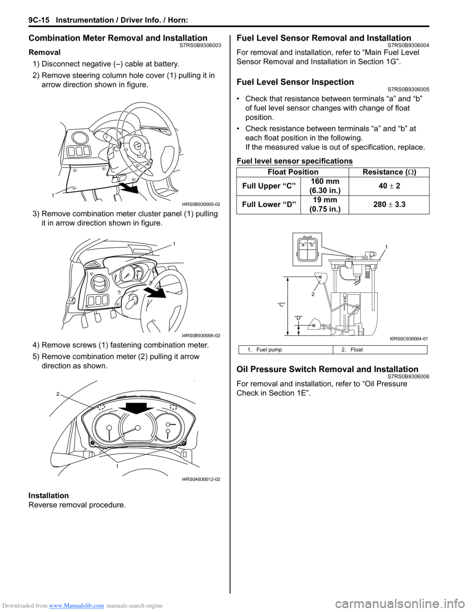
Removal1) Disconnect negative (–) cable at battery.
2) Remove steering column hole cover (1) pulling it in arrow direction shown in figure.
3) Remove combination mete r cluster panel (1) pulling
it in arrow direction shown in figure.
4) Remove screws (1) fast ening combination meter.
5) Remove combination me ter (2) pulling it arrow
direction as shown.
Installation
Reverse removal procedure.
Fuel Level Sensor Removal and InstallationS7RS0B9306004
For removal and installation, refer to “Main Fuel Level
Sensor Removal and Installation in Section 1G”.
Fuel Level Sensor InspectionS7RS0B9306005
• Check that resistance between terminals “a” and “b” of fuel level sensor changes with change of float
position.
• Check resistance between terminals “a” and “b” at each float position in the following.
If the measured value is out of specification, replace.
Fuel level sensor specifications
Oil Pressure Switch Removal and InstallationS7RS0B9306006
For removal and installation , refer to “Oil Pressure
Check in Section 1E”.
1
I4RS0B930005-02
1
I4RS0B930006-02
1
2
I4RS0A930012-02
Float Position Resistance (Ω)
Full Upper “C” 160 mm
(6.30 in.) 40
± 2
Full Lower “D” 19 mm
(0.75 in.) 280
± 3.3
1. Fuel pump 2. Float
“b”“a”
2
“C”
“D”
1
I6RS0C930004-01