Clutch torque SUZUKI SWIFT 2005 2.G Service Service Manual
[x] Cancel search | Manufacturer: SUZUKI, Model Year: 2005, Model line: SWIFT, Model: SUZUKI SWIFT 2005 2.GPages: 1496, PDF Size: 34.44 MB
Page 862 of 1496
Downloaded from www.Manualslib.com manuals search engine 5C-10 Clutch:
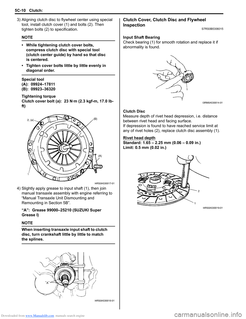
3) Aligning clutch disc to flywheel center using special
tool, install clutch cover (1) and bolts (2). Then
tighten bolts (2) to specification.
NOTE
• While tightening clutch cover bolts, compress clutch disc with special tool
(clutch center guide) by hand so that disc
is centered.
• Tighten cover bolts little by little evenly in diagonal order.
Special tool
(A): 09924–17811
(B): 09923–36320
Tightening torque
Clutch cover bolt (a): 23 N·m (2.3 kgf-m, 17.0 lb-
ft)
4) Slightly apply grease to input shaft (1), then join manual transaxle assembly with engine referring to
“Manual Transaxle Unit Dismounting and
Remounting in Section 5B”.
“A”: Grease 99000–25210 (SUZUKI Super
Grease I)
NOTE
When inserting transaxle input shaft to clutch
disc, turn crankshaft li ttle by little to match
the splines.
Clutch Cover, Clutch Disc and Flywheel
Inspection
S7RS0B5306015
Input Shaft Bearing
Check bearing (1) for smooth ro tation and replace it if
abnormality is found.
Clutch Disc
Measure depth of rivet head depression, i.e. distance
between rivet head and facing surface.
If depression is found to hav e reached service limit at
any of rivet holes (2), repl ace clutch disc assembly (1).
Rivet head depth
Standard: 1.65 – 2.25 mm (0.06 – 0.09 in.)
Limit: 0.5 mm (0.02 in.)
I4RS0A530017-01
I4RS0A530018-01
I3RM0A530014-01
I4RS0A530019-01
Page 864 of 1496
Downloaded from www.Manualslib.com manuals search engine 5C-12 Clutch:
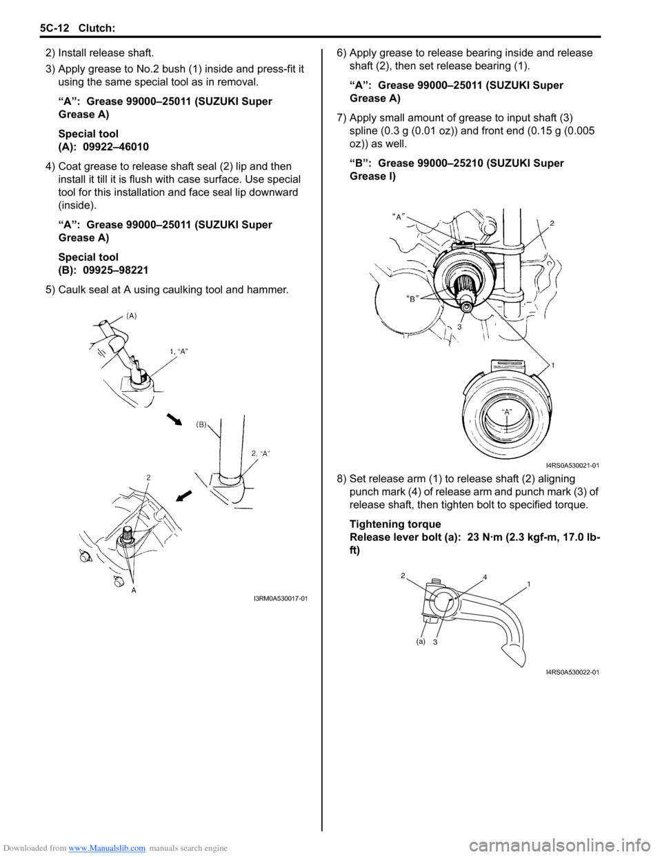
2) Install release shaft.
3) Apply grease to No.2 bush (1) inside and press-fit it using the same special tool as in removal.
“A”: Grease 99000–25011 (SUZUKI Super
Grease A)
Special tool
(A): 09922–46010
4) Coat grease to release shaft seal (2) lip and then install it till it is flush wit h case surface. Use special
tool for this installation a nd face seal lip downward
(inside).
“A”: Grease 99000–25011 (SUZUKI Super
Grease A)
Special tool
(B): 09925–98221
5) Caulk seal at A using caulking tool and hammer. 6) Apply grease to release bearing inside and release
shaft (2), then set release bearing (1).
“A”: Grease 99000–25011 (SUZUKI Super
Grease A)
7) Apply small amount of grease to input shaft (3) spline (0.3 g (0.01 oz)) and front end (0.15 g (0.005
oz)) as well.
“B”: Grease 99000–25210 (SUZUKI Super
Grease I)
8) Set release arm (1) to release shaft (2) aligning punch mark (4) of release arm and punch mark (3) of
release shaft, then tighten bolt to specified torque.
Tightening torque
Release lever bolt (a): 23 N·m (2.3 kgf-m, 17.0 lb-
ft)
I3RM0A530017-01
I4RS0A530021-01
(a)3
241
I4RS0A530022-01
Page 865 of 1496
Downloaded from www.Manualslib.com manuals search engine Clutch: 5C-13
Clutch Release System InspectionS7RS0B5306017
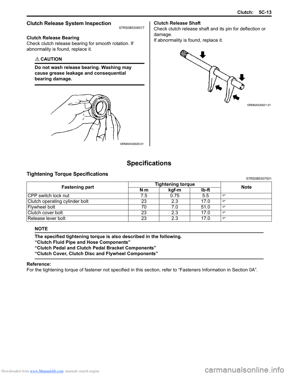
Clutch Release Bearing
Check clutch release bearing for smooth rotation. If
abnormality is found, replace it.
CAUTION!
Do not wash release bearing. Washing may
cause grease leakage and consequential
bearing damage.
Clutch Release Shaft
Check clutch release shaft and its pin for deflection or
damage.
If abnormality is found, replace it.
Specifications
Tightening Torque SpecificationsS7RS0B5307001
NOTE
The specified tightening torque is also described in the following.
“Clutch Fluid Pipe and Hose Components”
“Clutch Pedal and Clutch Pedal Bracket Components”
“Clutch Cover, Clutch Disc and Flywheel Components”
Reference:
For the tightening torque of fastener not specified in this section, refer to “Fasteners Information in Section 0A”.
I3RM0A530020-01
I3RM0A530021-01
Fastening part Tightening torque
Note
N ⋅mkgf-mlb-ft
CPP switch lock nut 7.5 0.75 5.5 �)
Clutch operating cylinder bolt 23 2.3 17.0 �)
Flywheel bolt 70 7.0 51.0 �)
Clutch cover bolt 23 2.3 17.0 �)
Release lever bolt 23 2.3 17.0 �)
Page 933 of 1496

Downloaded from www.Manualslib.com manuals search engine Table of Contents 7- i
7
Section 7
CONTENTS
HVAC
Precautions ................................................. 7-1
Precautions............................................................. 7-1
Precautions on HVAC ........................................... 7-1
Heater and Ventilation.... ......................... 7A-1
General Description ............................................. 7A-1
Heater and Ventilation Construction ................... 7A-1
Schematic and Routing Diagram ........................ 7A-2 Heater and Ventilation Wiring Circuit Diagram .... 7A-2
Diagnostic Information and Procedures ............ 7A-3 Heater and Ventilation Symptom Diagnosis........ 7A-3
Repair Instructions .............................................. 7A-4 HVAC Unit Components ..................................... 7A-4
HVAC Unit Removal and Installation .................. 7A-4
Blower Motor Removal and Installation............... 7A-4
Blower Motor Inspection ..................................... 7A-4
Blower Motor Resistor Removal and Installation ......................................................... 7A-5
Blower Motor Resistor Inspection ....................... 7A-5
Blower Motor Relay Inspection ........................... 7A-6
HVAC Control Unit Components ......................... 7A-6
HVAC Control Unit Remova l and Installation ...... 7A-7
Blower Speed Selector In spection ...................... 7A-9
Air Intake Selector Inspec tion ............................. 7A-9
Air Intake Control Actuator Removal and Installation ......................................................... 7A-9
Air Intake Control Actuator Inspection .............. 7A-10
Center Ventilation Louver Removal and Installation ....................................................... 7A-10
Side Ventilation Louver Removal and Installation ....................................................... 7A-11
HVAC Air Filter Removal and Installation (If Equipped)........................................................ 7A-12
HVAC Air Filter Inspection (If Equipped) ........... 7A-12
Air Conditioning System... ...................... 7B-1
Manual Type ............................................................ 7B-1
Precautions........................................................... 7B-1A/C System Caution ............................................ 7B-1
Precautions on Servicing A/C System ................ 7B-1
General Description ............................................. 7B-3 Refrigerant Type Identifica tion ............................ 7B-3
Sub-Cool A/C System Description ...................... 7B-4
A/C Operation Description .................................. 7B-4 Schematic and Routing Diagram ........................7B-5
Major Components of A/C System ...................... 7B-5
A/C System Wiring Diagram ............................... 7B-6
Diagnostic Information and Procedures ............7B-7 A/C System Symptom Diagnosis ........................ 7B-7
Abnormal Noise Sympto m Diagnosis of A/C
System .............................................................. 7B-9
A/C System Performance Inspection ................ 7B-10
A/C System Inspection at ECM ......................... 7B-15
Repair Instructions ........... .................................7B-16
Operation Procedure for Re frigerant Charge .... 7B-16
Condenser Assembly On-Vehicle Inspection .... 7B-21
Condenser Assembly Removal and Installation ....................................................... 7B-21
Receiver/Dryer Removal and Installation .......... 7B-22
HVAC Unit Components ................................... 7B-23
HVAC Unit Removal and In stallation ................ 7B-24
Evaporator Inspection ....................................... 7B-24
Evaporator Thermistor (Evaporator Temperature Sensor) Removal and
Installation ....................................................... 7B-25
Evaporator Thermistor (Evaporator Temperature Sensor) Inspec tion..................... 7B-25
Expansion Valve Removal and Installation ....... 7B-26
Expansion Valve Inspection .............................. 7B-26
A/C Refrigerant Pressure Sensor and Its Circuit Inspection............................................. 7B-26
A/C Refrigerant Pressu re Sensor Removal
and Installation ................................................ 7B-26
A/C Switch Inspection ....................................... 7B-27
Compressor Relay Inspection ........................... 7B-27
Compressor Drive Belt Inspection and Adjustment ...................................................... 7B-27
Compressor Drive Belt Removal and Installation ....................................................... 7B-28
Compressor Assembly Removal and Installation ....................................................... 7B-28
Compressor Assembly Components................. 7B-29
Magnet Clutch Inspection.................................. 7B-29
Magnet Clutch Removal and Installation........... 7B-29
Relief Valve Inspection...................................... 7B-31
Relief Valve Removal and Installation............... 7B-32
Specifications .................... .................................7B-32
Tightening Torque Specifications ...................... 7B-32
Special Tools and Equipmen t ...........................7B-33
Page 979 of 1496
Downloaded from www.Manualslib.com manuals search engine Air Conditioning System: Manual Type 7B-31
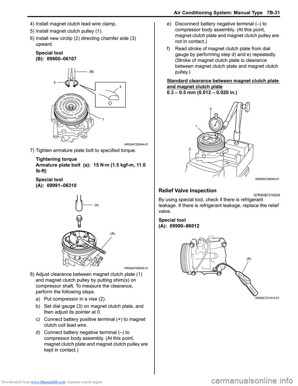
4) Install magnet clutch lead wire clamp.
5) Install magnet clutch pulley (1).
6) Install new circlip (2) directing chamfer side (3) upward.
Special tool
(B): 09900–06107
7) Tighten armature plate bolt to specified torque. Tightening torque
Armature plate bolt (a): 15 N·m (1.5 kgf-m, 11.0
lb-ft)
Special tool
(A): 09991–06310
8) Adjust clearance between magnet clutch plate (1) and magnet clutch pulley by putting shim(s) on
compressor shaft. To measure the clearance,
perform the following steps.
a) Put compressor in a vise (2).
b) Set dial gauge (3) on magnet clutch plate, and then adjust its pointer at 0.
c) Connect battery positive terminal (+) to magnet clutch coil lead wire.
d) Connect battery negative terminal (–) to compressor body assemb ly. (At this point,
magnet clutch plate and magnet clutch pulley are
kept in contact.) e) Disconnect battery negative terminal (–) to
compressor body assembly. (At this point,
magnet clutch plate and magnet clutch pulley are
not in contact.)
f) Read stroke of magnet clutch plate from dial gauge by performing step d) and e) repeatedly.
(Stroke of magnet clutch plate is clearance
between magnet clutch plate and magnet clutch
pulley.)
Standard clearance between magnet clutch plate
and magnet clutch plate
0.3 – 0.5 mm (0.012 – 0.020 in.)
Relief Valve InspectionS7RS0B7216028
By using special tool, chec k if there is refrigerant
leakage. If there is refrigerant leakage, replace the relief
valve.
Special tool
(A): 09990–86012
1
32 (B)
I4RS0A720044-01
(a)
(A)
I4RS0A720045-01
21
3
I4RS0A720046-01
(A)
I5RS0C721014-01
Page 1187 of 1496
Downloaded from www.Manualslib.com manuals search engine Wiring Systems: 9A-16
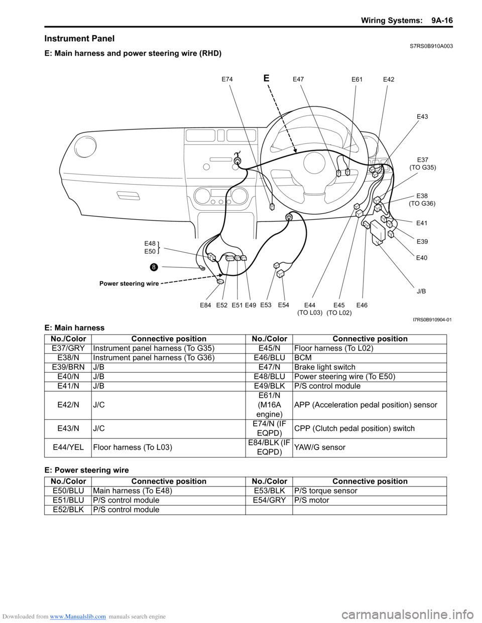
Instrument PanelS7RS0B910A003
E: Main harness and power steering wire (RHD)
E: Main harness
E: Power steering wire
J/B
E54
E53
E49
E51E52E84
E48
E50
Power steering wire
E47E74E42E61
E43
E45
(TO L02)
E44
(TO L03)E46
E40 E39
E41 E37
(TO G35)
E38
(TO G36)
8
E
I7RS0B910904-01
No./Color Connective position No./ColorConnective position
E37/GRY Instrument panel harness (To G35) E45/N Floor harness (To L02)
E38/N Instrument panel harness (To G36) E46/BLU BCM
E39/BRN J/B E47/N Brake light switch
E40/N J/B E48/BLU Power steering wire (To E50)
E41/N J/B E49/BLK P/S control module
E42/N J/C E61/N
(M16A
engine) APP (Acceleration pedal position) sensor
E43/N J/C E74/N (IF
EQPD) CPP (Clutch pedal position) switch
E44/YEL Floor harness (To L03) E84/BLK (IF
EQPD) YAW/G sensor
No./Color Connective position No./ColorConnective position
E50/BLU Main harness (To E48) E53/BLK P/S torque sensor
E51/BLU P/S control module E54/GRY P/S motor
E52/BLK P/S control module