Ac control SUZUKI SWIFT 2005 2.G Service Workshop Manual
[x] Cancel search | Manufacturer: SUZUKI, Model Year: 2005, Model line: SWIFT, Model: SUZUKI SWIFT 2005 2.GPages: 1496, PDF Size: 34.44 MB
Page 1385 of 1496
Downloaded from www.Manualslib.com manuals search engine Body Structure: 9K-8
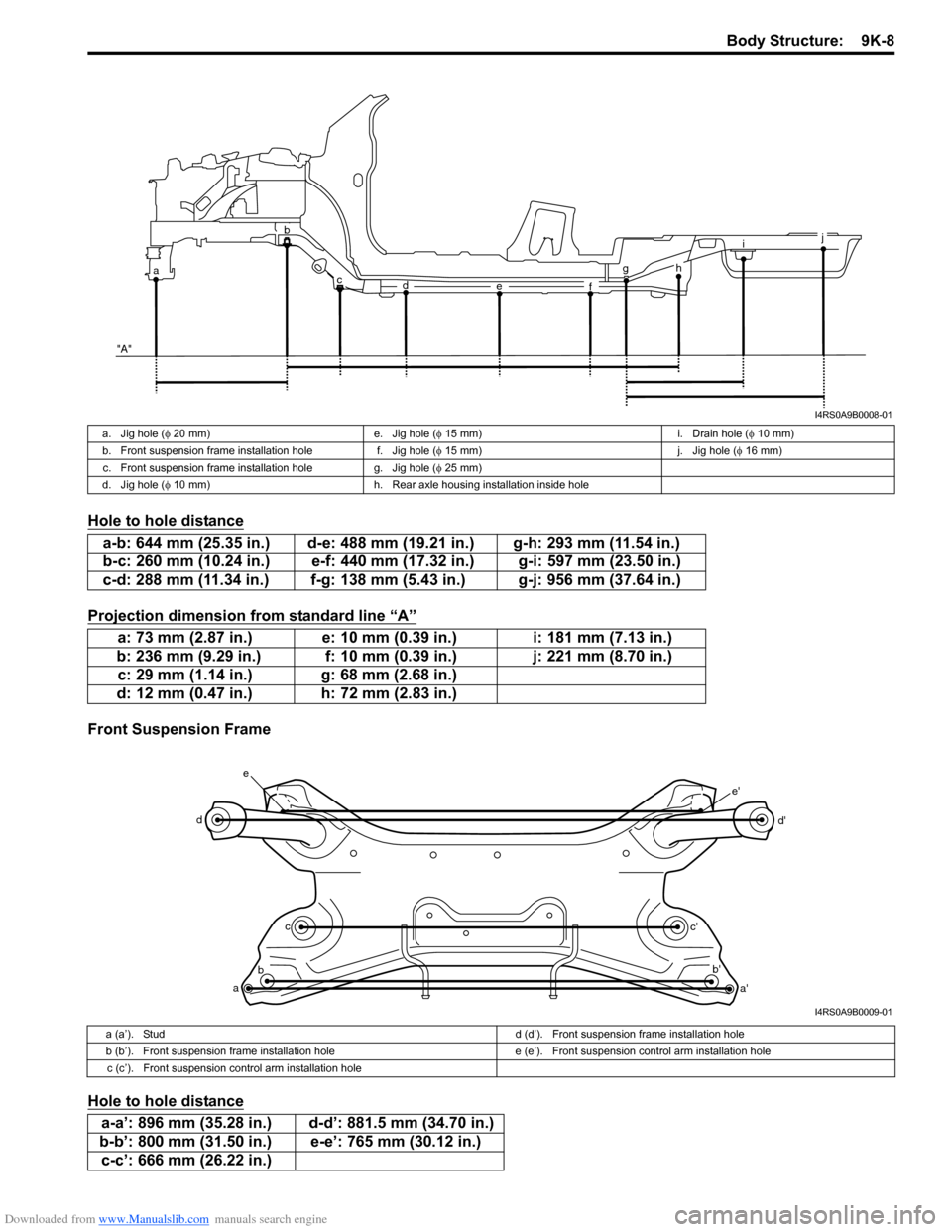
Hole to hole distance
Projection dimension from standard line “A”
Front Suspension Frame
Hole to hole distance
i
g
f
e
d
c
ab
"A"j
h
I4RS0A9B0008-01
a. Jig hole ( φ 20 mm) e. Jig hole ( φ 15 mm) i. Drain hole ( φ 10 mm)
b. Front suspension frame installation hole f. Jig hole (φ 15 mm) j. Jig hole (φ 16 mm)
c. Front suspension frame installation hole g. Jig hole ( φ 25 mm)
d. Jig hole ( φ 10 mm) h. Rear axle housing installation inside hole
a-b: 644 mm (25.35 in.) d-e: 488 mm (19.21 in.) g-h: 293 mm (11.54 in.)
b-c: 260 mm (10.24 in.) e-f: 440 mm (17.32 in.) g-i: 597 mm (23.50 in.)
c-d: 288 mm (11.34 in.) f-g: 138 mm (5.43 in.) g-j: 956 mm (37.64 in.)
a: 73 mm (2.87 in.) e: 10 mm (0.39 in.) i: 181 mm (7.13 in.)
b: 236 mm (9.29 in.) f: 10 mm (0.39 in.) j: 221 mm (8.70 in.) c: 29 mm (1.14 in.) g: 68 mm (2.68 in.)
d: 12 mm (0.47 in.) h: 72 mm (2.83 in.)
a b c
d
e
a'
b'
c' d'
e'
I4RS0A9B0009-01
a (a’). Stud
d (d’). Front suspension frame installation hole
b (b’). Front suspension frame installation hole e (e’). Front suspension control arm installation hole
c (c’). Front suspension control arm installation hole
a-a’: 896 mm (35.28 in.) d-d’: 881.5 mm (34.70 in.)
b-b’: 800 mm (31.50 in.) e-e’: 765 mm (30.12 in.) c-c’: 666 mm (26.22 in.)
Page 1386 of 1496
Downloaded from www.Manualslib.com manuals search engine 9K-9 Body Structure:
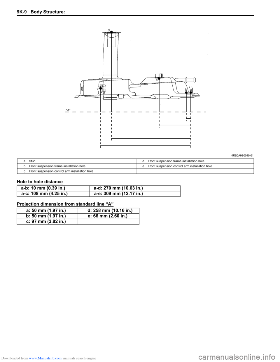
Hole to hole distance
Projection dimension from standard line “A”
I4RS0A9B0010-01
a. Studd. Front suspension frame installation hole
b. Front suspension frame installation hole e. Front suspension control arm installation hole
c. Front suspension control arm installation hole
a-b: 10 mm (0.39 in.) a-d: 270 mm (10.63 in.)
a-c: 108 mm (4.25 in.) a-e: 309 mm (12.17 in.)
a: 50 mm (1.97 in.) d: 258 mm (10.16 in.)
b: 50 mm (1.97 in.) e: 66 mm (2.60 in.)
c: 97 mm (3.82 in.)
Page 1401 of 1496
Downloaded from www.Manualslib.com manuals search engine Table of Contents 10- i
10
Section 10
CONTENTS
Control Systems
Precautions ............................................... 10-1
Precautions........................................................... 10-1
Precautions for Control Systems......................... 10-1
Body Electrical Contro l System ........... 10B-1
Precautions......................................................... 10B-1
Precautions in Diagnosing Trouble ................... 10B-1
General Description ........................................... 10B-1 BCM General Description ................................. 10B-1
CAN Communication System Description......... 10B-2
Theft Deterrent Light ......................................... 10B-3
Security Alarm Description (If Equipped) .......... 10B-3
Schematic and Routing Diagram ...................... 10B-4 Body Electrical Control System Wiring Circuit Diagram .......................................................... 10B-4
Connector Layout Diagram of BCM and Junction Block Assembly ................................ 10B-7
Component Locatio n ......................................... 10B-8
BCM and Related System Component Location .......................................................... 10B-8
Diagnostic Information an d Procedures .......... 10B-9
BCM Self-Diagnosis Function ........................... 10B-9
Body Electrical Control System Check............ 10B-10
Scan Tool Data ............................................... 10B-12
DTC Table ....................................................... 10B-14
DTC Check ..................................................... 10B-14
DTC Clearance ............................................... 10B-15
BCM Power Circuit and Ground Circuit Check 10B-16
DTC B1133 (DTC No. 1133): Battery Voltage Too High ....................................................... 10B-17
DTC B1141 / DTC B1142 (No. 1141 / No. 1142): Outside Air Temperature (Ambient
Temp.) Sensor Circuit Ma lfunction ................ 10B-18
DTC B1150 (No. 1150): Air Bag Communication Circuit Malfunction .............. 10B-19
DTC B1157 (No. 1157): Air Bag Deployment Signal Input ................................................... 10B-20
DTC B1170 (No. 1170 ): EEPROM Access
Error .............................................................. 10B-21
DTC U0155 (No. 0155): Lost Communication with Instrument Panel Cluster (IPC) Control
Module .......................................................... 10B-21
DTC U1073 (No. 1073): Control Module Communication Bus Off ................................ 10B-24 DTC U1100 (No. 1100): Lost Communication
with ECM ....................................................... 10B-25
DTC U1101 (No. 1101): Lost Communication with TCM ....................................................... 10B-27
DTC U1144 (No. 1144): Lost Communication with Keyless Start Control Module ................ 10B-29
Inspection of BCM and its Circuits .................. 10B-31
Repair Instructions ........... ...............................10B-39
BCM (Included in Junction Block Assembly) Removal and Installation ............................... 10B-39
Outside Air Temperature Sensor Removal and Installation .............................................. 10B-39
Outside Air Temperature Sensor Inspection ... 10B-39
Security Alarm Mode Selection Procedure (If Equipped) ...................................................... 10B-39
Special Tools and Equipmen t .........................10B-40
Special Tool .................................................... 10B-40
Immobilizer Control Syst em ................. 10C-1
Precautions.........................................................10C-1
Precautions in Diagnosing Troubles .................10C-1
Precaution in Replacing ECM ...........................10C-1
Precautions in Handli ng Immobilizer Control
System ............................................................10C-1
General Description ...........................................10C-2 Immobilizer Control System Introduction ..........10C-2
Immobilizer Control System Components Location...........................................................10C-3
On-Board Diagnostic System Description (Self-diagnosis Function) ................................10C-3
Schematic and Routing Diag ram ......................10C-4
Immobilizer Control System Wiring Circuit Diagram...........................................................10C-4
Diagnostic Information an d Procedures ..........10C-5
Immobilizer Control System Check ...................10C-5
Diagnostic Trouble Code (DTC) Check.............10C-5
Diagnostic Trouble Code (DTC) Clearance ......10C-6
Diagnostic Trouble Code (DTC) Table ..............10C-6
Scan Tool Data .................................................10C-7
Immobilizer Indicator Lamp Does Not Come ON with Ignition Switch ON and Engine Stop ..10C-7
Immobilizer Indicator Lamp Remains ON after Engine Starts...................................................10C-8
DTC P1614: Transponder Re sponse Error .......10C-9
Page 1402 of 1496
Downloaded from www.Manualslib.com manuals search engine 10-ii Table of Contents
DTC P1615: ID Code Does Not Registered (Vehicle equipped with keyless start system
only) ................................................................10C-9
DTC P1616: Different Registration ID Codes (Vehicle equipped with keyless start system
only) ..............................................................10C-10
DTC P1618: CAN Communication Error (Reception Error for Keyless Start Control
Module) (Vehicle equipped with keyless
start system only) ..........................................10C-11
DTC P1621: Immobilizer Communication Line Error ......................................................10C-12
DTC P1622: EEPROM Reading / Writing Error ..............................................................10C-13
DTC P1623: Unregistered Transponder .........10C-13
DTC P1625: Immobilizer An tenna Error..........10C-14
DTC P1636: Immobilizer Information Registration Failure .......................................10C-14
DTC P1638: Immobilizer Information Mismatched ...................................................10C-15
Inspection of Immobilizer Control Module (ICM) and Its Circuit ....... ...............................10C-16
Repair Instructions ........... ...............................10C-18
Immobilizer Control Mo dule (ICM) Removal
and Installation ..............................................10C-18
Registration of the Ignition Key .......................10C-18
Procedure after ECM Replacement ................10C-18
Special Tools and Equipmen t .........................10C-19
Special Tool ....................................................10C-19
Keyless Start System ....... ......................10E-1
General Description ........................................... 10E-1
Keyless Start System Description ..................... 10E-1
Parts and Functions .......................................... 10E-2
Keyless Engine Start Function .......................... 10E-3
Door Lock Function of Keyless Start System .... 10E-4
Operation Area of Remote Controller................ 10E-5
Alarm Function .................................................. 10E-6
CAN Communication System Description......... 10E-6
Schematic and Routing Diagram ...................... 10E-7 Keyless Start System El ectric Wiring Circuit
Diagram .......................................................... 10E-7
Diagnostic Information and Procedures .......... 10E-8 Precautions in Diagnosing Troubles ................. 10E-8
Self-Diagnosis Function .................................... 10E-8
Keyless Start System Diagn osis Introduction ... 10E-8 Keyless Start System Chec
k ............................. 10E-8
Customer Questionnaire (E xample) .................. 10E-9
Key Indicator Lamp Check .............................. 10E-10
DTC Check...................................................... 10E-10
DTC Table ....................................................... 10E-11
DTC Clearance ............................................... 10E-12
Keyless Start System Symp tom Diagnosis ..... 10E-12
Keyless Start System Operation Inspection .... 10E-13
Door Lock Operation (Keyless Start System) . 10E-14
Inspection of Keyless Start Control Module and Its Circuits .............................................. 10E-14
No DTC Detection After Performing DTC Check ............................................................ 10E-18
Key Indicator Lamp Circuit Check (Key indicator lamp doesn’t light when ignition
knob switch is pushed.) ................................. 10E-20
Keyless Start Control Module Power and Ground Circuit Check .................................... 10E-22
DTC No. 11: Communi cation Error with
Steering Lock Unit ......................................... 10E-23
DTC No. 13 / No. 14: Release Signal Error from Steering Lock Unit / Steering Lock Unit
Malfunction .................................................... 10E-24
DTC No. 21 / No. 22: Internal Error of Keyless Start Control Module (EEPROM reading
error) / (EEPROM writing error) ............ ........ 10E-24
DTC No. 31: Lost Commun ication with BCM .. 10E-25
DTC No. 33: Control Module Communication
Bus Off .......................................................... 10E-27
DTC No. 51 / No. 52 / No. 53: Driver Side / Passenger Side / Rear End Door Request
Switch Failure................................................ 10E-28
Repair Instructions ............ .............................. 10E-30
Antennas and Request Switches Removal and Installation .............................................. 10E-30
Front Door (Driver and Passenger Side), Rear End Door Request Switch Inspection............ 10E-31
Steering Lock Unit Removal and Installation .. 10E-31
Steering Lock Unit Inspection ......................... 10E-31
Front Door Lock Switch In spection ................. 10E-31
Keyless Start Control Module Removal and Installation ..................................................... 10E-32
Remote Controller Inspection.......................... 10E-32
Replacement of Remote Controller Battery .... 10E-32
Registration Procedure for Remote Controller
ID Code ......................................................... 10E-33
Page 1403 of 1496

Downloaded from www.Manualslib.com manuals search engine Precautions: 10-1
Control Systems
Precautions
Precautions
Precautions for Control SystemsS7RS0BA000001
Air Bag Warning
Refer to “Air Bag Warning in Section 00”.
Page 1404 of 1496
Downloaded from www.Manualslib.com manuals search engine 10B-1 Body Electrical Control System:
Control Systems
Body Electrical Control System
Precautions
Precautions in Diagnosing TroubleS7RS0BA200001
• Diagnostic information stored in BCM memory can be cleared as well as checked by using SUZUKI scan tool.
Before using scan tool, read its Operator ’s (Instruction) Manual carefully to have good understanding as to what
functions are available and how to use it.
• Be sure to read “Precautions for Electrical Circuit Serv ice in Section 00” before inspection and observe what is
written there.
• Communication of ECM, TCM (if equipped), ABS/ESP ® control module, steering angle sensor (ESP ® model),
keyless start control module (if equipped), combinatio n meter and BCM is established by CAN (Controller Area
Network). For detail of CAN communication for BCM, refer to “CAN Communication System Description”.
Therefore, handle CAN communication line with care referr ing to “Precaution for CAN Communication System in
Section 00”.
General Description
BCM General DescriptionS7RS0BA201001
The Body electrical Control Module (BCM) is incorporated in junction block assembly. Do not attempt removal of BCM
from junction block assembly as it may cause contact failure.
The BCM incorporates relays and controllers which are used for the following systems and controls them.
• Power door lock
• Keyless entry (if equipped)
• Door lock function of keyle ss start system (if equipped)
• Rear wiper
• Combination meter
• Interior light
• Warning buzzer
• Rear end door window defogger and door mirror heater (if equipped)
• Rear end door opener
• Theft deterrent light
Also, the BCM has a function to cause the interior light and open door warning lamp in the combination meter to turn
off when any door is left open for longer than 15 minutes to reduce wasteful battery consumption.
In addition, it is possible to check operation of actuator whic h is controlled by BCM by using the output test function of
SUZUKI scan tool to operate actuator simulatively.
Page 1405 of 1496
Downloaded from www.Manualslib.com manuals search engine Body Electrical Control System: 10B-2
CAN Communication System DescriptionS7RS0BA201002
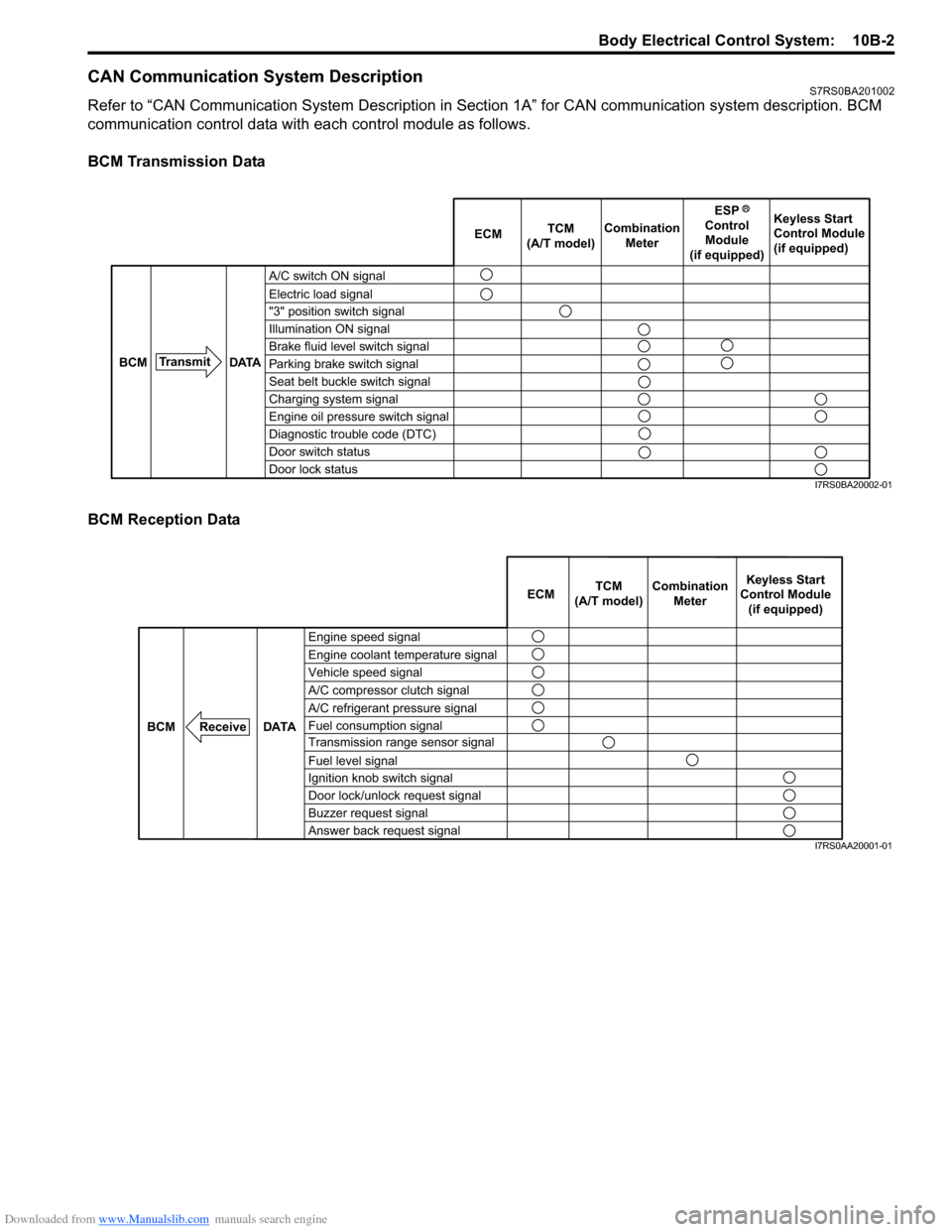
Refer to “CAN Communication System Description in Section 1A” for CAN communication system description. BCM
communication control data with ea ch control module as follows.
BCM Transmission Data
BCM Reception Data
A/C switch ON signal
Electric load signal
"3" position switch signal
Illumination ON signal
Brake fluid level switch signal
Parking brake switch signal
Seat belt buckle switch signal
Charging system signal
Engine oil pressure switch signal
Diagnostic trouble code (DTC)
Door switch status
Door lock status ECM
TCM
(A/T model) Combination
Meter Keyless Start
Control Module
(if equipped)
Transmit DATA
BCM
ESP
Control Module
(if equipped)
I7RS0BA20002-01
Engine speed signal
Vehicle speed signal Engine coolant temperature signal
A/C refrigerant pressure signal
Fuel consumption signal A/C compressor clutch signal
Transmission range sensor signal
Fuel level signal
Ignition knob switch signal
Door lock/unlock request signal
Buzzer request signal
Answer back request signal
DATA
BCM
Receive
Combination
Meter
TCM
(A/T model) Keyless Start
Control Module (if equipped)
ECM
I7RS0AA20001-01
Page 1406 of 1496
Downloaded from www.Manualslib.com manuals search engine 10B-3 Body Electrical Control System:
Theft Deterrent LightS7RS0BA201003
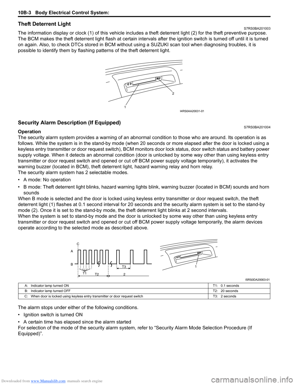
The information display or clock (1) of this vehicle includes a theft deterrent light (2) for the theft preventive purpose.
The BCM makes the theft deterrent light flash at certain interval s after the ignition switch is turned off until it is turned
on again. Also, to check DTCs stored in BCM without usin g a SUZUKI scan tool when diagnosing troubles, it is
possible to identify them by flashing patterns of the theft deterrent light.
Security Alarm Description (If Equipped)S7RS0BA201004
Operation
The security alarm system provides a warning of an abnormal condition to those who are around. Its operation is as
follows. While the system is in the stand- by mode (when 20 seconds or more elapsed after the door is locked using a
keyless entry transmitter or door request switch), BCM monitors door lock status, door switch status and battery power
supply voltage. When it detects an abnormal condition (door is unlocked by some way other than using keyless entry
transmitter or door request switch and opened or cut off BCM power supply voltage temporarily), it activates the
warning buzzer (located in BCM), theft deterr ent light, hazard warning relay and horn relay.
The security alarm system has 2 selectable modes.
• A mode: No operation
• B mode: Theft deterrent light blinks, hazard warning lights blink, warning buzzer (located in BCM) sounds and horn
sounds
When B mode is selected and the door is locked using keyl ess entry transmitter or door request switch, the theft
deterrent light (1) flashes at 0.1 second interval for 20 seconds and the se curity alarm system is set to the stand-by
mode (2). Once it is se t to the stand-by mode, the theft deterrent light blinks at 2 second intervals.
When the system is set to stand-by mode and the door is unlocked by some way other than using keyless entry
transmitter or door request switch and opened or cut off BCM power supply voltage temporarily, the alarm devices
operate according to the selected mode as described above.
The alarm stops under either of the following conditions.
• Ignition switch is turned ON
• A certain time has elapsed since the alarm started
For selection of the mode of the security alarm system , refer to “Security Alarm Mode Selection Procedure (If
Equipped)”.
1 2I4RS0AA20031-01
B A1T3
T1
T2 2
C
I5RS0DA20003-01
A: Indicator lamp turned ON
T1: 0.1 seconds
B: Indicator lamp turned OFF T2: 20 seconds
C: When door is locked using keyless entry tr ansmitter or door request switch T3: 2 seconds
Page 1407 of 1496
Downloaded from www.Manualslib.com manuals search engine Body Electrical Control System: 10B-4
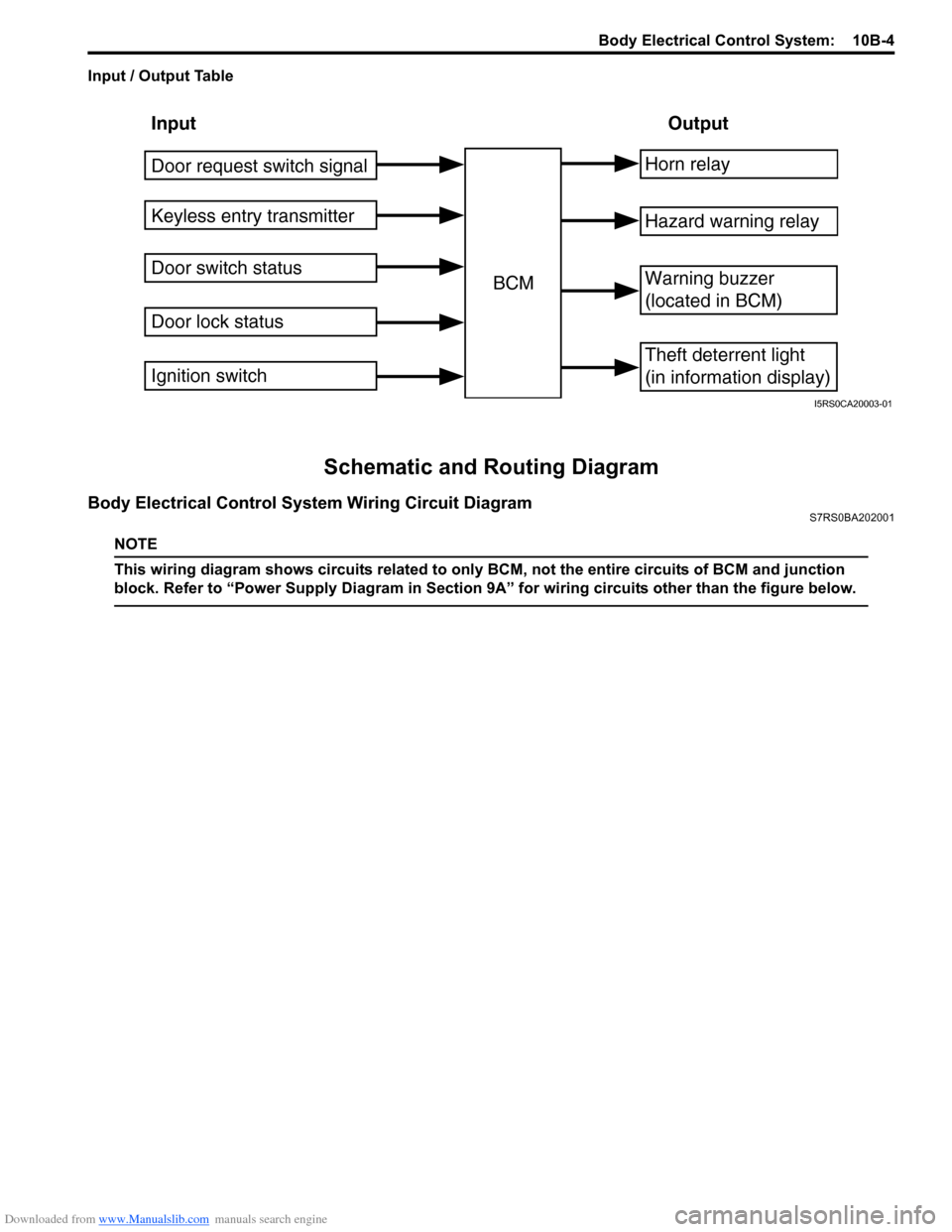
Input / Output Table
Schematic and Routing Diagram
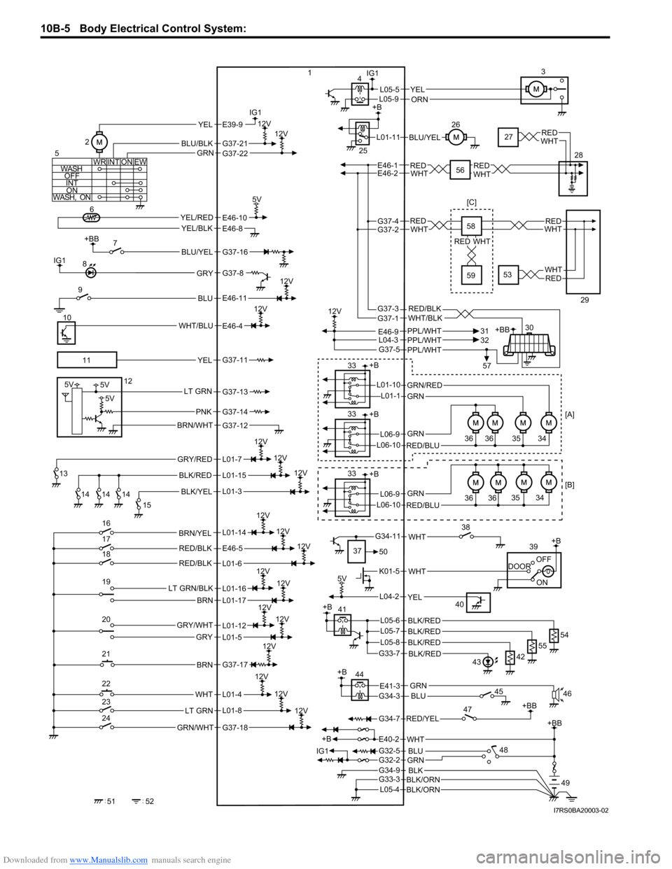
Body Electrical Control System Wiring Circuit DiagramS7RS0BA202001
NOTE
This wiring diagram shows circuits related to only BCM, not the entire circuits of BCM and junction
block. Refer to “Power Supply Diagram in Section 9A” for wiring circuits other than the figure below.
Input Output
Keyless entry transmitter
Door switch status
Door lock status BCMHorn relay
Theft deterrent light
(in information display)
Warning buzzer
(located in BCM)
Hazard warning relay
Door request switch signal
Ignition switch
I5RS0CA20003-01
Page 1408 of 1496
Downloaded from www.Manualslib.com manuals search engine 10B-5 Body Electrical Control System:
GRY/RED
BLK/YEL
BLK/RED
12V
12V
+BB
BLU/YEL
BLU
12V
WHT/BLU
12V
+BB
RED/YEL
G34-7
YEL/REDYEL/BLK
5V
IG1
IG1
IG1
WASH
OFFINT ON
WASH, ON WR EWON
INT
BLU/BLK
YELE39-9
GRN
12V12V
YELL05-5
BLU/YEL
PPL/WHT
12V
G37-5PPL/WHTPPL/WHT
+B +B
GRN/RED
GRN
GRN
RED/BLU
L06-9
L06-10
L01-10L01-1
ON
DOOR
OFF+B
+B
IG1 WHT
K01-5
12V
12V
12V
5V
12V
12V
L04-2YEL
RED/BLK
WHT
GRN/WHT
BRN
LT GRN/BLK
BRN
GRY/WHT
GRY
12VLT GRN
12V
12V
12V
12V
RED/BLK
LT GRN
BRN/WHT
5V5V
5V
PNK
+BB
GRNG32-2
+B
BLKBLK/ORNG34-9
G33-3
BLK/ORNL05-4
BLU
G32-5
WHTE40-2
G34-11
E41-3G34-3BLU
REDWHTREDWHT
+BB
1
2 3
4
5 67
8
9
10
11 12
13 14 14 14 15
16
17
18
19
20
21
22
23
24
52
51 25
26
28
30
31
32
33
33 36 36
+B
GRN
RED/BLU
L06-9
L06-10
33
36 3635 34
35 34
37 50 38
39
40
45 46
47
48 49
[B] [A]
[C]
G37-21
E46-10
GRY
YEL
BRN/YEL
L01-12
L01-4
L01-8
L01-11
GRN
WHT
G37-22
E46-4
G37-8
E46-8
G37-16
E46-11
G37-11
G37-13
G37-14
G37-12
L01-7
L01-15
L01-3
L01-14
L01-16
E46-5
L01-6
L01-17
L01-5
G37-17
G37-18
E46-1E46-2
E46-9
+B
12V
12V
BLK/RED
BLK/REDL05-6
G33-7 54
BLK/REDL05-7
55
BLK/REDL05-842
43
44
27REDWHT
57
+B41
56
ORNL05-9
L04-3
REDWHTREDWHT
REDWHT
REDWHT
G37-4G37-2
RED/BLKWHT/BLKG37-3G37-1 58
59
29
53
I7RS0BA20003-02