Coolant system SUZUKI SWIFT 2005 2.G Service Repair Manual
[x] Cancel search | Manufacturer: SUZUKI, Model Year: 2005, Model line: SWIFT, Model: SUZUKI SWIFT 2005 2.GPages: 1496, PDF Size: 34.44 MB
Page 374 of 1496
Downloaded from www.Manualslib.com manuals search engine 1F-11 Engine Cooling System:
Water Pump Removal and InstallationS7RS0B1606014
Removal1) Disconnect negative cable at battery.
2) Drain coolant.
3) Remove water pump / generator drive belt referring to “Water Pump / Generator Drive Belt Removal and
Installation in Section 1J”.
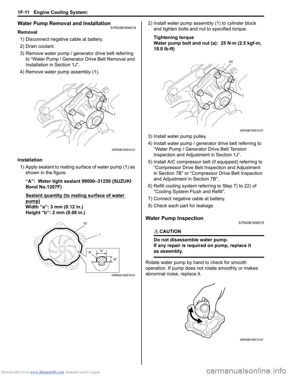
4) Remove water pump assembly (1).
Installation 1) Apply sealant to mating surface of water pump (1) as shown in the figure.
“A”: Water tight sealant 99000–31250 (SUZUKI
Bond No.1207F)
Sealant quantity (to mating surface of water
pump)
Width “a”: 3 mm (0.12 in.)
Height “b”: 2 mm (0.08 in.) 2) Install water pump assemb
ly (1) to cylinder block
and tighten bolts and nut to specified torque.
Tightening torque
Water pump bolt and nut (a): 25 N·m (2.5 kgf-m,
18.0 lb-ft)
3) Install water pump pulley.
4) Install water pump / generator drive belt referring to “Water Pump / Generator Drive Belt Tension
Inspection and Adjustment in Section 1J”.
5) Install A/C compressor belt (if equipped) referring to “Compressor Drive Belt Inspection and Adjustment
in Section 7B” or “Compressor Drive Belt Inspection
and Adjustment in Section 7B”.
6) Refill cooling system referri ng to Step 7) to 22) of
“Cooling System Flush and Refill”.
7) Connect negative cable at battery.
8) Check each part for leakage.
Water Pump InspectionS7RS0B1606015
CAUTION!
Do not disassemble water pump.
If any repair is requir ed on pump, replace it
as assembly.
Rotate water pump by hand to check for smooth
operation. If pump does not rotate smoothly or makes
abnormal noise, replace it.
I2RH0B160016-01
I3RM0A160016-01
I2RH0B160018-01
I2RH0B160019-01
Page 653 of 1496
Downloaded from www.Manualslib.com manuals search engine Automatic Transmission/Transaxle: 5A-9
CAN Communication System DescriptionS7RS0B5101007
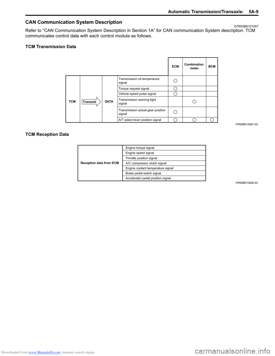
Refer to “CAN Communication System Description in Section 1A” for CAN communication System description. TCM
communicates control data with each control module as follows.
TCM Transmission Data
TCM Reception Data
DATA
TCM
Transmit
Transmission oil temperarure
signal
Torque request signal
Vehicle speed pulse signal
Transmission warning light
signal
Transmission actual gear position
signal
A/T select lever position signal
ECMCombination
meterBCM
I7RS0B510001-03
Engine torque signal
Engine speed signal
Throttle position signal
A/C compressor clutch signal
Engine coolant temperature signal
Brake pedal switch signal
Reception data from ECM
Accelerator pedal position signalI7RS0B510002-03
Page 662 of 1496

Downloaded from www.Manualslib.com manuals search engine 5A-18 Automatic Transmission/Transaxle:
Visual InspectionS7RS0B5104002
Visually check the following parts and systems.
Malfunction Indicator Lamp (MIL) CheckS7RS0B5104003
Refer to the same item in “Malfunction Indicator Lam p (MIL) Check in Section 1A” for checking procedure.
Transmission Warning Light CheckS7RS0B5104004
1) Turn ignition switch ON.
2) Check that transmission warning light lights for about 2 – 4 sec. and then goes OFF.
If anything faulty is found, advance “Transmission Warn ing Light Circuit Check – Light Does Not Come “ON” at
Ignition Switch ON” or “Transmission Warning Light Circu it Check – Light Remains “ON” at Ignition Switch ON”.
Inspection item Referring
• A/T fluid ----- level, leakage, color “Automatic Transaxle Fluid Level Inspection in Section 0B”
• A/T fluid hoses ----- disconnection, looseness, deterioration “A/T Fluid Cooler Hoses Replacement”
• A/T select cable ----- installation “S elect Cable Removal and Installation”
• Engine oil ----- level, leakage “Engine Oil and Filter Change in Section 0B”
• Engine coolant ----- level, leakage “Engine Coolant Change in Section 0B”
• Engine mountings ----- play, looseness, damage “Engine Assembly Removal and Installation in Section 1D”
• Suspension ----- play, looseness “Suspension, Wheels and Tires Symptom Diagnosis in Section 2A”
• Drive shafts ----- damage “Front Drive Shaft Assembly On-Vehicle Inspection in Section 3A”
• Battery ----- indicator condition, corrosion of terminal “Battery Inspection in Section 1J”
• Connectors of electric wire harness ----- disconnection, friction “Electronic Shift Control System Components
Location”
• Fuses ----- burning
• Parts ----- installation, damage
• Bolts ----- looseness
• Other parts that can be checked visually
Also check the following items at engine start, if possible.
• Transmission warning light (if equipped) ----- Operation “Transmission Warning Light Check”
• Malfunction indicator lamp ----- Operation “Malfunction Indicator Lamp (MIL) Check”
• Charge warning lamp ----- Operation “Generator Symptom Diagnosis in Section 1J”
• Engine oil pressure warning lamp ----- Operation “Oil Pressure Warning Ligh t Symptom Diagnosis in
Section 9C”
• Engine coolant temp. meter ----- Operation “Engine Coolant Temperature (ECT) Meter
Symptom Diagnosis in Section 9C”
• Other parts that can be checked visually
I4RS0A510008-01
Page 670 of 1496
Downloaded from www.Manualslib.com manuals search engine 5A-26 Automatic Transmission/Transaxle:
TRANSAXLE RANGE
Transaxle range detected by signal fed from
transmission range sensor.
D RANGE SIGNAL
ON: Signal which TCM require ECM to increase idle
speed
OFF: Signal which TCM does not require ECM to
increase idle speed
THROTTLE POSITION (%)
Throttle opening ratio computed by CAN signal from
ECM.
BRAKE SWITCH
Inputted signal from brake light switch on pedal bracket.
ON: Brake pedal depressed
OFF: Brake pedal released
TORQUE REDUCTION SIGNAL
ON: Signal which TCM require ECM to reduce output
torque at shifting gear
OFF: Signal which TCM does not require ECM to reduce
output torque
ENGINE COOLANT TEMPERATURE ( °C, °F)
Engine coolant temperature computed by CAN signal
from ECM. AIR CONDITIONER SIGNAL
ON: Signal which inform that air conditioner compressor
is turned ON.
OFF: Signal which inform that air conditioner
compressor is not turned ON.
ENGINE TORQUE SIGNAL (N
⋅m)
Engine torque computed by duty pulse signal outputted
from ECM.
SLIP RPM (RPM)
This parameter indicates slip ping rotation in the torque
converter (difference between input shaft rotation and
engine rotation)
MIL REQUEST
ON: Signal which TCM requires combination meter to
turn on malfunction indicator lamp.
OFF: Signal which TCM does not require combination
meter to turn on malf unction indicator lamp.
FUEL CUT FLAG
ON: Signal which inform that fuel cut is operating.
OFF: Signal which inform that fuel cut is not operating.
A/T Basic CheckS7RS0B5104010
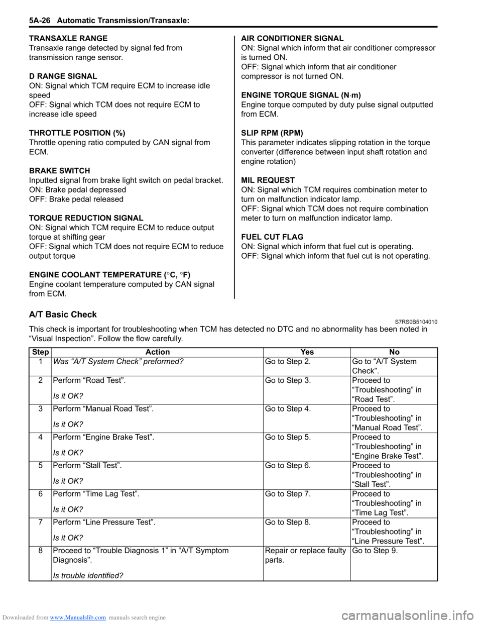
This check is important for troubleshooting when TCM has detected no DTC and no abnormality has been noted in
“Visual Inspection”. Fo llow the flow carefully.
Step Action YesNo
1 Was “A/T System Check” preformed? Go to Step 2.Go to “A/T System
Check”.
2 Perform “Road Test”.
Is it OK? Go to Step 3.
Proceed to
“Troubleshooting” in
“Road Test”.
3 Perform “Manual Road Test”.
Is it OK? Go to Step 4.
Proceed to
“Troubleshooting” in
“Manual Road Test”.
4 Perform “Engine Brake Test”.
Is it OK? Go to Step 5.
Proceed to
“Troubleshooting” in
“Engine Brake Test”.
5 Perform “Stall Test”.
Is it OK? Go to Step 6.
Proceed to
“Troubleshooting” in
“Stall Test”.
6 Perform “Time Lag Test”.
Is it OK? Go to Step 7.
Proceed to
“Troubleshooting” in
“Time Lag Test”.
7 Perform “Line Pressure Test”.
Is it OK? Go to Step 8.
Proceed to
“Troubleshooting” in
“Line Pressure Test”.
8 Proceed to “Trouble Diag nosis 1” in “A/T Symptom
Diagnosis”.
Is trouble identified? Repair or replace faulty
parts.
Go to Step 9.
Page 681 of 1496
Downloaded from www.Manualslib.com manuals search engine Automatic Transmission/Transaxle: 5A-37
Non operate TCC (lock-
up) systemTCC pressure control solenoid valve
circuit faulty Inspect circuit for open, short and intermittent.
If NG, repair.
Shift solenoid valve-A and/or-B circuit
faulty Inspect circuit for open, short and intermittent.
If NG, repair.
Pressure control solenoid valve circuit
faulty Inspect circuit for open, short and intermittent.
If NG, repair.
Output shaft speed sensor circuit faulty Inspect circuit for open, short and intermittent.
If NG, repair.
Input shaft speed sensor circuit faulty Inspect circuit for open, short and intermittent.
If NG, repair.
Transmission range sensor circuit faulty Inspect circuit for open, short and intermittent.
If NG, repair.
Transmission fluid temperature sensor
circuit faulty Inspect circuit for open, short and intermittent.
If NG, repair.
CAN communication circuit faulty Inspect circuit for open, short and intermittent.
If NG, repair.
Throttle position sensor circuit faulty Inspect circuit for open, short and intermittent
referring to “Electric Throttle Body Assembly
On-Vehicle Inspection in Section 1C”. If NG,
repair.
Engine coolant temperature sensor
circuit faulty Inspect circuit for open, short and intermittent
referring to “DTC P0117: Engine Coolant
Temperature Circuit Low
in Section 1A” and/or
“DTC P0118: Engine Coolant Temperature
Circuit High in Section 1A”. If NG, repair.
Brake light switch circuit faulty Refer to “No Lock-Up Occurs”.
TCM Substitute a known-good TCM and recheck.
ECM Substitute a known-good ECM and recheck.
Higher or lower stall
speed Pressure control solenoid valve circuit
faulty Inspect circuit for open, short and intermittent.
If NG, repair.
TCM Substitute a known-good TCM and recheck.
Excessive “N”
→ “D” or
“N”
→ “R” time lag Pressure control solenoid valve circuit
faulty Inspect circuit for open, short and intermittent.
If NG, repair.
Transmission fluid temperature sensor
circuit faulty Inspect circuit for open, short and intermittent.
If NG, repair.
TCM Substitute a known-good TCM and recheck.
Higher or lower line
pressure Pressure control solenoid valve circuit
faulty Inspect circuit for open, short and intermittent.
If NG, repair.
TCM Substitute a known-good TCM and recheck.
Condition Possible cause Correction / Reference Item
Page 684 of 1496
Downloaded from www.Manualslib.com manuals search engine 5A-40 Automatic Transmission/Transaxle:
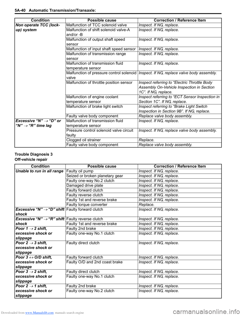
Trouble Diagnosis 3
Off-vehicle repairNon operate TCC (lock-
up) system
Malfunction of TCC solenoid valve
Inspect. If NG, replace.
Malfunction of shift solenoid valve-A
and/or -B Inspect. If NG, replace.
Malfunction of output shaft speed
sensor Inspect. If NG, replace.
Malfunction of input shaft speed sensor Inspect. If NG, replace.
Malfunction of transmission range
sensor Inspect. If NG, replace.
Malfunction of transmission fluid
temperature sensor Inspect. If NG, replace.
Malfunction of pressure control solenoid
valve Inspect. If NG, replace valve body assembly.
Malfunction of throttle position sensor Inspect referring to “Electric Throttle Body
Assembly On-Vehicle Inspection in Section
1C”. If NG, replace.
Malfunction of engine coolant
temperature sensor Inspect referring to “ECT Sensor Inspection in
Section 1C”. If NG, replace.
Malfunction of brake light switch Inspect referring to “Brake Light Switch
Inspection in Section 9B”. If NG, replace.
Faulty valve body component Replace valve body assembly.
Excessive “N”
→ “D” or
“N”
→ “R” time lag Malfunction of transmission fluid
temperature sensor Inspect. If NG, replace.
Pressure control solenoid valve circuit
faulty Inspect. If NG, replace valve body assembly.
Clogged oil strainer Replace.
Faulty valve body component Replace valve body assembly.
Condition Possible cause Correction / Reference Item
Condition
Possible cause Correction / Reference Item
Unable to run in all range Faulty oil pump Inspect. If NG, replace.
Seized or broken planetary gear Inspect. If NG, replace.
Faulty one-way No.2 clutch Inspect. If NG, replace.
Damaged drive plate Inspect. If NG, replace.
Faulty forward clutch Inspect. If NG, replace.
Faulty reverse clutch Inspect. If NG, replace.
Faulty 1st and reverse brake Inspect. If NG, replace.
Faulty torque converter Replace.
Excessive “N”
→ “D” shift
shock Faulty forward clutch
Inspect. If NG, replace.
Excessive “N”
→ “R” shift
shock Faulty reverse clutch
Inspect. If NG, replace.
Faulty 1st and reverse brake Inspect. If NG, replace.
Poor 1
→ 2 shift,
excessive shock or
slippage Faulty 2nd brake
Inspect. If NG, replace.
Faulty one-way No.1 clutch Inspect. If NG, replace.
Poor 2
→ 3 shift,
excessive shock or
slippage Faulty direct clutch
Inspect. If NG, replace.
Poor 3
↔ O/D shift,
excessive shock or
slippage Faulty forward clutch
Inspect. If NG, replace.
Faulty O/D and 2nd coast brake Inspect. If NG, replace.
Poor 3
→ 2 shift,
excessive shock or
slippage Faulty direct clutch
Inspect. If NG, replace.
Faulty one-way No.1 clutch Inspect. If NG, replace.
Poor 2
→ 1 shift,
excessive shock or
slippage Faulty 2nd brake
Inspect. If NG, replace.
Faulty one-way No.2 clutch Inspect. If NG, replace.
Page 685 of 1496
Downloaded from www.Manualslib.com manuals search engine Automatic Transmission/Transaxle: 5A-41
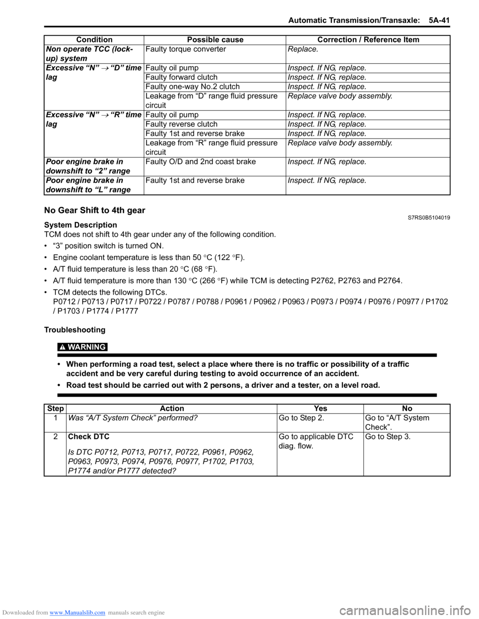
No Gear Shift to 4th gearS7RS0B5104019
System Description
TCM does not shift to 4th gear under any of the following condition.
• “3” position switch is turned ON.
• Engine coolant temperature is less than 50 °C (122 °F).
• A/T fluid temperature is less than 20 °C (68 °F).
• A/T fluid temperature is more than 130 °C (266 °F) while TCM is detecting P2762, P2763 and P2764.
• TCM detects the following DTCs. P0712 / P0713 / P0717 / P0722 / P0787 / P0788 / P0961 / P0962 / P0963 / P0973 / P0974 / P0976 / P0977 / P1702
/ P1703 / P1774 / P1777
Troubleshooting
WARNING!
• When performing a road test, select a place where there is no traffic or possibility of a traffic accident and be very careful during testing to avoid occurrence of an accident.
• Road test should be carried out with 2 persons, a driver and a tester, on a level road.
Non operate TCC (lock-
up) system Faulty torque converter
Replace.
Excessive “N”
→ “D” time
lag Faulty oil pump
Inspect. If NG, replace.
Faulty forward clutch Inspect. If NG, replace.
Faulty one-way No.2 clutch Inspect. If NG, replace.
Leakage from “D” range fluid pressure
circuit Replace valve body assembly.
Excessive “N”
→ “R” time
lag Faulty oil pump
Inspect. If NG, replace.
Faulty reverse clutch Inspect. If NG, replace.
Faulty 1st and reverse brake Inspect. If NG, replace.
Leakage from “R” range fluid pressure
circuit Replace valve body assembly.
Poor engine brake in
downshift to “2” range Faulty O/D and 2nd coast brake
Inspect. If NG, replace.
Poor engine brake in
downshift to “L” range Faulty 1st and reverse brake
Inspect. If NG, replace.
Condition Possible cause Correction / Reference Item
Step
Action YesNo
1 Was “A/T System Check” performed? Go to Step 2.Go to “A/T System
Check”.
2 Check DTC
Is DTC P0712, P0713, P0717, P0722, P0961, P0962,
P0963, P0973, P0974, P0976, P0977, P1702, P1703,
P1774 and/or P1777 detected? Go to applicable DTC
diag. flow.
Go to Step 3.
Page 686 of 1496
Downloaded from www.Manualslib.com manuals search engine 5A-42 Automatic Transmission/Transaxle:
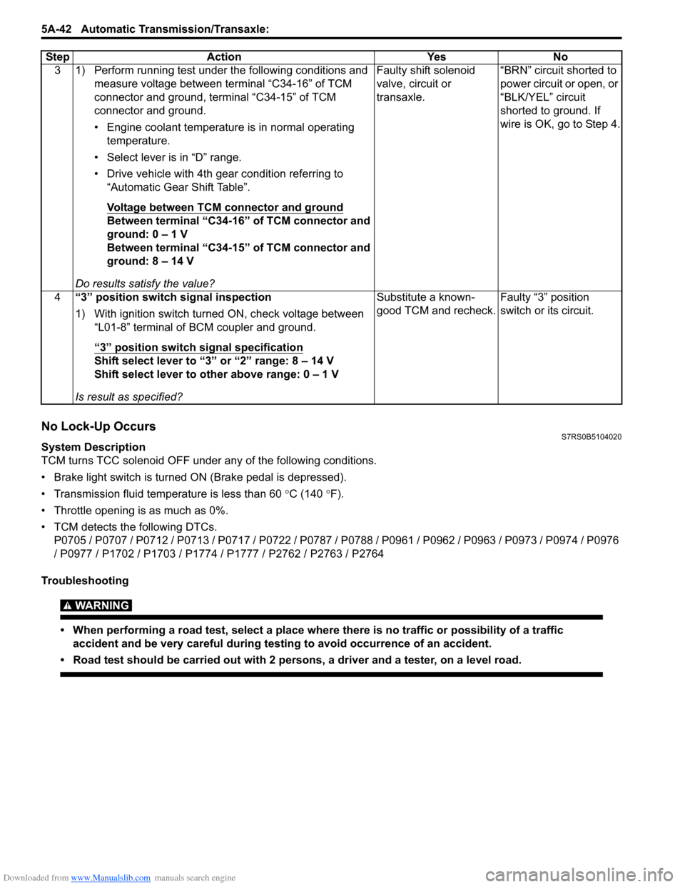
No Lock-Up OccursS7RS0B5104020
System Description
TCM turns TCC solenoid OFF under any of the following conditions.
• Brake light switch is turned ON (Brake pedal is depressed).
• Transmission fluid temperat ure is less than 60 °C (140 °F).
• Throttle opening is as much as 0%.
• TCM detects the following DTCs. P0705 / P0707 / P0712 / P0713 / P0717 / P0722 / P0787 / P0788 / P0961 / P0962 / P0963 / P0973 / P0974 / P0976
/ P0977 / P1702 / P1703 / P1774 / P1777 / P2762 / P2763 / P2764
Troubleshooting
WARNING!
• When performing a road test, select a place where there is no traffic or possibility of a traffic accident and be very careful during testing to avoid occurrence of an accident.
• Road test should be carried out with 2 persons, a driver and a tester, on a level road.
3 1) Perform running test under the following conditions and measure voltage between terminal “C34-16” of TCM
connector and ground, terminal “C34-15” of TCM
connector and ground.
• Engine coolant temperature is in normal operating temperature.
• Select lever is in “D” range.
• Drive vehicle with 4th gear condition referring to “Automatic Gear Shift Table”.
Voltage between TCM connector and ground
Between terminal “C34-16” of TCM connector and
ground: 0 – 1 V
Between terminal “C34-15” of TCM connector and
ground: 8 – 14 V
Do results satisfy the value? Faulty shift solenoid
valve, circuit or
transaxle.
“BRN” circuit shorted to
power circuit or open, or
“BLK/YEL” circuit
shorted to ground. If
wire is OK, go to Step 4.
4 “3” position switch signal inspection
1) With ignition switch turned ON, check voltage between
“L01-8” terminal of BCM coupler and ground.
“3” position switch signal specification
Shift select lever to “3” or “2” range: 8 – 14 V
Shift select lever to other above range: 0 – 1 V
Is result as specified? Substitute a known-
good TCM and recheck.
Faulty “3” position
switch or its circuit.
Step Action Yes No
Page 824 of 1496
Downloaded from www.Manualslib.com manuals search engine 5B-10 Manual Transmission/Transaxle:
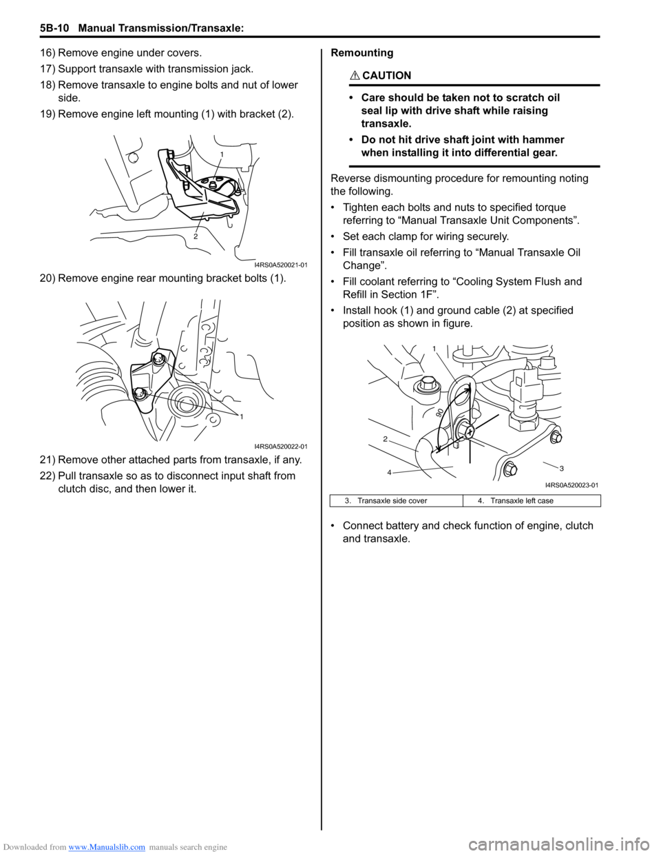
16) Remove engine under covers.
17) Support transaxle with transmission jack.
18) Remove transaxle to engine bolts and nut of lower side.
19) Remove engine left mounting (1) with bracket (2).
20) Remove engine rear mounting bracket bolts (1).
21) Remove other attached parts from transaxle, if any.
22) Pull transaxle so as to disconnect input shaft from clutch disc, and then lower it. Remounting
CAUTION!
• Care should be taken not to scratch oil
seal lip with drive shaft while raising
transaxle.
• Do not hit drive shaft joint with hammer when installing it into differential gear.
Reverse dismounting procedure for remounting noting
the following.
• Tighten each bolts and nuts to specified torque referring to “Manual Transaxle Unit Components”.
• Set each clamp for wiring securely.
• Fill transaxle oil referring to “Manual Transaxle Oil
Change”.
• Fill coolant referring to “Cooling System Flush and
Refill in Section 1F”.
• Install hook (1) and ground cable (2) at specified position as shown in figure.
• Connect battery and check function of engine, clutch
and transaxle.
1
2
I4RS0A520021-01
1
I4RS0A520022-01
3. Transaxle side cover 4. Transaxle left case
90
1
2 3
4
I4RS0A520023-01
Page 934 of 1496

Downloaded from www.Manualslib.com manuals search engine 7-ii Table of Contents
Recommended Service Material ....................... 7B-33
Special Tool ...................................................... 7B-33
Automatic Type .................... .................................7B-34
Precautions.........................................................7B-34 A/C System Caution .......................................... 7B-34
Precautions in Diagnosing Trouble ................... 7B-34
Precautions on Servicing A/C System .............. 7B-34
General Description .......... .................................7B-34
Auto A/C System Descript ion ............................ 7B-34
HVAC Control Module Operation Description ... 7B-36
Refrigerant Type Identifica tion .......................... 7B-36
Sub-Cool A/C System Description .................... 7B-36
A/C Operation Description ................................ 7B-36
On-Board Diagnostic System Description ......... 7B-37
Schematic and Routing Diagram ......................7B-37 Major Components of A/C System .................... 7B-37
A/C System Wiring Diagra m ............................. 7B-38
Diagnostic Information and Procedures ..........7B-39 A/C System Symptom Diagnosis ...................... 7B-39
Abnormal Noise Sympto m Diagnosis of A/C
System ............................................................ 7B-42
DTC Check........................................................ 7B-42
DTC Clearance ................................................. 7B-43
DTC Table ......................................................... 7B-44
Fail-Safe Table ................. ................................. 7B-45
Scan Tool Data ................................................. 7B-46
Air Conditioning System Check......................... 7B-47
Visual Inspection ............................................... 7B-49
DTC B1502: Inside Air Temperature Sensor and/or Its Circuit Malfunction .......................... 7B-49
DTC B1503: A/C Evaporator Air Temperature Sensor and/or Its Circuit Malfunction .............. 7B-50
DTC B1504: Sunload Sensor and/or Its Circuit Malfunction ......... ................................. 7B-52
DTC B1511: Temperature Control Actuator (Position Sensor) and/or Its Circuit
Malfunction ...................................................... 7B-53
DTC B1512: Air flow Control Actuator (Position Sensor) and/or Its Circuit
Malfunction ...................................................... 7B-55
DTC B1513: Temperature Control Actuator and/or Its Circuit Malfunction .......................... 7B-57
DTC B1514: Air Flow Co ntrol Actuator and/or
Its Circuit Malfunction ...................................... 7B-60
DTC B1541: HVAC Control Module Back-Up Power Supply Malfunction .............................. 7B-62
DTC B1546: A/C Refrigerant Pressure Malfunction ...................................................... 7B-63
DTC B1551: Serial Communication Circuit Malfunction ...................................................... 7B-63
DTC B1552: Serial Communication Signal Malfunction ...................................................... 7B-64
DTC B1553: CAN Communication Signal Malfunction ...................................................... 7B-65
DTC B1557: Vehicle Speed Sensor Signal Malfunction ...................................................... 7B-65
DTC B1561: Engine Coolant Temperature Sensor Signal Malfunctio n .............................. 7B-66 DTC B1562: Outside Air Temperature Sensor
Signal Malfunction ........................................... 7B-66
DTC B1563: A/C Refr igerant Pressure
Sensor Signal Malfunction .............................. 7B-66
Inspection of HVAC Control Module and Its Circuit .............................................................. 7B-67
A/C System Performance Inspection ................ 7B-70
A/C System Inspection at ECM ......................... 7B-70
Repair Instructions ............ ................................7B-71
Operation Procedure for Refrigerant Charge .... 7B-71
HVAC Unit Components ................................... 7B-72
HVAC Unit Removal and In stallation ................ 7B-73
Temperature Control Actuator Removal and Installation ....................................................... 7B-73
Temperature Control Actuat or Inspection ......... 7B-73
Air Flow Control Actuator Removal and Installation ....................................................... 7B-74
Air Flow Control Actuator Inspection ................. 7B-74
Air Intake Control Actuator Removal and Installation ....................................................... 7B-75
Air Intake Control Actuator Inspection............... 7B-75
Actuator Linkage Inspection .............................. 7B-76
Blower Motor Controller Removal and Installation ....................................................... 7B-76
Blower Motor Controller Inspection ................... 7B-76
HVAC Control Module Removal and Installation ....................................................... 7B-77
Sunload Sensor Removal and Installation ........ 7B-77
Sunload Sensor Inspection ............................... 7B-77
Outside Air Temperature Sensor Removal and Installation ................................................ 7B-77
Outside Air Temperature Sensor Inspection ..... 7B-77
Inside Air Temperature Sensor Removal and Installation ....................................................... 7B-78
Inside Air Temperature Sens or Inspection ........ 7B-78
Condenser Assembly On-Vehicle Inspection .... 7B-78
Condenser Assembly Removal and Installation ....................................................... 7B-78
Receiver/Dryer Removal and Installation .......... 7B-78
Evaporator Inspection ....................................... 7B-78
Evaporator Temperature Sensor Removal and Installation ................................................ 7B-78
Evaporator Temperature Se nsor Inspection ..... 7B-78
Expansion Valve Removal an d Installation ....... 7B-78
Expansion Valve Inspection .............................. 7B-78
A/C Refrigerant Pressure Sensor and Its Circuit Inspection............................................. 7B-78
A/C Refrigerant Pressu re Sensor Removal
and Installation ................................................ 7B-78
Compressor Relay Inspection .
.......................... 7B-78
Compressor Drive Belt Inspection and Adjustment ...................................................... 7B-78
Compressor Drive Belt Removal and Installation ....................................................... 7B-79
Compressor Assembly Removal and Installation ....................................................... 7B-79
Compressor Assembly Components................. 7B-79
Magnet Clutch Removal and Installation........... 7B-79
Magnet Clutch Inspection.................................. 7B-79
Relief Valve Inspection...................................... 7B-79