Body control modul SUZUKI SWIFT 2005 2.G Service Manual PDF
[x] Cancel search | Manufacturer: SUZUKI, Model Year: 2005, Model line: SWIFT, Model: SUZUKI SWIFT 2005 2.GPages: 1496, PDF Size: 34.44 MB
Page 1003 of 1496
Downloaded from www.Manualslib.com manuals search engine Air Conditioning System: Automatic Type 7B-55
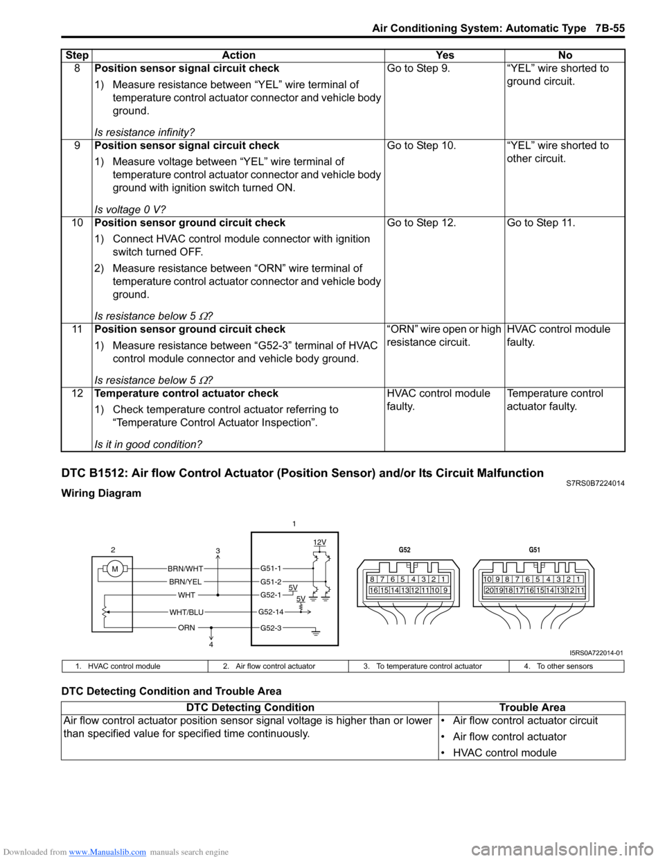
DTC B1512: Air flow Control Actuator (Position Sensor) and/or Its Circuit MalfunctionS7RS0B7224014
Wiring Diagram
DTC Detecting Condition and Trouble Area8
Position sensor signal circuit check
1) Measure resistance between “YEL” wire terminal of
temperature control actuator connector and vehicle body
ground.
Is resistance infinity? Go to Step 9. “YEL” wire shorted to
ground circuit.
9 Position sensor signal circuit check
1) Measure voltage between “YEL” wire terminal of
temperature control actuator connector and vehicle body
ground with ignition switch turned ON.
Is voltage 0 V? Go to Step 10. “YEL” wire shorted to
other circuit.
10 Position sensor ground circuit check
1) Connect HVAC control module connector with ignition
switch turned OFF.
2) Measure resistance between “ORN” wire terminal of temperature control actuator connector and vehicle body
ground.
Is resistance below 5
Ω? Go to Step 12. Go to Step 11.
11 Position sensor ground circuit check
1) Measure resistance between “G52-3” terminal of HVAC
control module connector and vehicle body ground.
Is resistance below 5
Ω? “ORN” wire open or high
resistance circuit.
HVAC control module
faulty.
12 Temperature control actuator check
1) Check temperature control actuator referring to
“Temperature Control Actuator Inspection”.
Is it in good condition? HVAC control module
faulty.
Temperature control
actuator faulty.
Step Action Yes No
7812910
65 431516 14 13 12 11
G52
789101920121112
65 431718 16 15 14 13
G51
M 12V
5V 5V
WHT/BLU
WHT
BRN/WHT
BRN/YEL
2
1
ORN
G51-1
G51-2
G52-1
G52-14
G52-3
3
4
I5RS0A722014-01
1. HVAC control module 2. Air flow control actuator3.To temperature control actuator 4. To other sensors
DTC Detecting Condition Trouble Area
Air flow control actuator position sensor signal voltage is higher than or lower
than specified value for specified time continuously. • Air flow control actuator circuit
• Air flow control actuator
• HVAC control module
Page 1004 of 1496
Downloaded from www.Manualslib.com manuals search engine 7B-56 Air Conditioning System: Automatic Type
DTC TroubleshootingStep Action YesNo
1 Position sensor power supply circuit check
1) Disconnect air flow control actuator connector.
2) Check for proper connection to air flow control actuator
at “WHT”, “WHT/BLU” and “ORN” wire terminals.
3) If OK, measure voltage between “WHT” wire terminal of air flow control actuator connector and vehicle body
ground with ignition switch turned ON.
Is voltage 4 – 6 V? Go to Step 6.
Go to Step 2.
2 Position sensor power supply circuit check
1) Disconnect temperature control actuator connector with
ignition switch turned OFF.
2) Measure voltage between “WHT” wire terminal of air flow control actuator connector and vehicle body ground with
ignition switch turned ON.
Is voltage 4 – 6 V? Temperature control
actuator faulty.
Go to Step 3.
3 Position sensor power supply circuit check
1) Disconnect connector from HVAC control module with
ignition switch turned OFF.
2) Check for proper connection to HVAC control module connector at “G52-1”, “G52-3” and “G52-14” terminals.
3) If OK, measure resistance between “WHT” wire terminal of air flow control actuator connector and “G52-1”
terminal of HVAC control module connector.
Is resistance below 5
Ω? Go to Step 4. “WHT” wire open or
high resistance circuit.
4 Position sensor power supply circuit check
1) Measure resistance between “WHT” wire terminal of air
flow control actuator connector and vehicle body ground.
Is resistance infinity? Go to Step 5. “WHT” wire shorted to
ground circuit.
5 Position sensor power supply circuit check
1) Measure voltage between “WHT” wire terminal of air flow
control actuator connector and vehicle body ground with
ignition switch turned ON.
Is voltage 0 V? Go to Step 6. “WHT” wire shorted to
other circuit.
6 Position sensor signal circuit check
1) Connect HVAC control module connector with ignition
switch turned OFF.
2) Measure voltage between “WHT/BLU” wire terminal of air flow control actuator connector and vehicle body
ground with ignition switch turned ON.
Is voltage 4 – 6 V? Go to Step 10. Go to Step 7.
7 Position sensor signal circuit check
1) Disconnect connector from HVAC control module with
ignition switch turned OFF.
2) Measure resistance between “WHT/BLU” wire terminal of air flow control actuator connector and “G52-14”
terminal of HVAC control module connector.
Is resistance below 5
Ω? Go to Step 8. “WHT/BLU” wire open
or high resistance
circuit.
Page 1005 of 1496
Downloaded from www.Manualslib.com manuals search engine Air Conditioning System: Automatic Type 7B-57
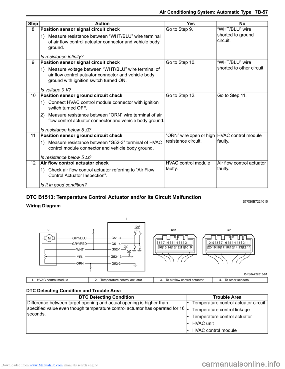
DTC B1513: Temperature Control Actuator and/or Its Circuit MalfunctionS7RS0B7224015
Wiring Diagram
DTC Detecting Condition and Trouble Area8
Position sensor signal circuit check
1) Measure resistance between “WHT/BLU” wire terminal
of air flow control actuator connector and vehicle body
ground.
Is resistance infinity? Go to Step 9. “WHT/BLU” wire
shorted to ground
circuit.
9 Position sensor signal circuit check
1) Measure voltage between “WHT/BLU” wire terminal of
air flow control actuator connector and vehicle body
ground with ignition switch turned ON.
Is voltage 0 V? Go to Step 10. “WHT/BLU” wire
shorted to other circuit.
10 Position sensor ground circuit check
1) Connect HVAC control module connector with ignition
switch turned OFF.
2) Measure resistance between “ORN” wire terminal of air flow control actuator connector and vehicle body ground.
Is resistance below 5
Ω? Go to Step 12. Go to Step 11.
11 Position sensor ground circuit check
1) Measure resistance between “G52-3” terminal of HVAC
control module connector and vehicle body ground.
Is resistance below 5
Ω? “ORN” wire open or high
resistance circuit.
HVAC control module
faulty.
12 Air flow control actuator check
1) Check air flow control actuator referring to “Air Flow
Control Actuator Inspection”.
Is it in good condition? HVAC control module
faulty.
Air flow control actuator
faulty.
Step Action Yes No
7812910
65 431516 14 13 12 11
G52
789101920121112
65 431718 16 15 14 13
G51
M 12V
5V 5V
YEL
WHT
GRY/BLU
GRY/RED
2
1
ORN
G51-3
G51-4
G52-1
G52-13
G52-3
3
4
I5RS0A722013-01
1. HVAC control module 2. Temperature control actuator 3. To air flow control actuator 4. To other sensors
DTC Detecting Condition Trouble Area
Difference between target opening an d actual opening is higher than
specified value even though temperature control actuator has operated for 16
seconds. • Temperature control actuator circuit
• Temperature control linkage
• Temperature control actuator
• HVAC unit
• HVAC control module
Page 1006 of 1496
Downloaded from www.Manualslib.com manuals search engine 7B-58 Air Conditioning System: Automatic Type
DTC Troubleshooting
NOTE
• When DTC B1502, B1503 and B1514 are indicated together, it is possible that “ORN” wire circuit open.
• When DTC B1514 is indicated together, it is possible that “WHT” wire circuit open.
Step Action YesNo
1 DTC check
1) Connect scan tool to DLC with ignition switch turned
OFF.
2) Turn ON ignition switch and check DTC.
Is there DTC B1511? Go to applicable DTC
diag. flow.
Go to Step 2.
2 Visual check
1) Check if there is any obstruction in operating range of
actuator linkage and if actuator linkage operates
smoothly.
Is it in good condition? Go to Step 3.
Obstruction in operating
range of actuator
linkage, actuator linkage
faulty and/or internal
fault of HVAC unit.
3 Wire harness check
1) Disconnect connector from temperature control actuator
with ignition swit ch turned OFF.
2) Check for proper connection to temperature control actuator connector at “GRY /BLU” and “GRY/RED” wire
terminals.
3) If OK, measure voltage between “GRY/BLU” wire terminal of temperature control actuator connector and
vehicle body ground with ignition switch turned ON when
temperature selector is operation to COOL direction.
Is voltage 10 – 14 V? Go to Step 7.
Go to Step 4.
4 Wire harness check
1) Disconnect connector from HVAC control module with
ignition switch turned OFF.
2) Check for proper connection to HVAC control module connector at “G51-3” and “G51-4” terminals.
3) If OK, measure resistance between “GRY/BLU” wire terminal of temperature control actuator connector and
“G51-3” terminal of HVAC control module connector.
Is resistance below 5
Ω? Go to Step 5. “GRY/BLU” wire open or
high resistance circuit.
5 Wire harness check
1) Measure resistance between “GRY/BLU” wire terminal
of temperature control actuator connector and vehicle
body ground.
Is resistance infinity? Go to Step 6.
“GRY/BLU” wire shorted
to ground circuit.
6 Wire harness check
1) Measure voltage between “GRY/BLU” wire terminal of
temperature control actuator connector and vehicle body
ground with ignition switch turned ON.
Is voltage 0 V? Go to Step 7.
“GRY/BLU” wire shorted
to other circuit.
Page 1007 of 1496
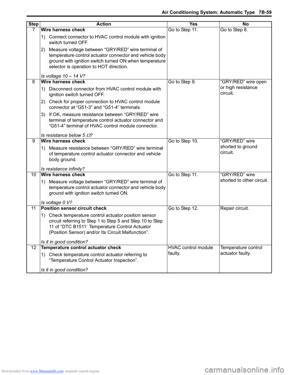
Downloaded from www.Manualslib.com manuals search engine Air Conditioning System: Automatic Type 7B-59
7Wire harness check
1) Connect connector to HVAC control module with ignition
switch turned OFF.
2) Measure voltage between “GRY/RED” wire terminal of temperature control actuator connector and vehicle body
ground with ignition switch turned ON when temperature
selector is operation to HOT direction.
Is voltage 10 – 14 V? Go to Step 11. Go to Step 8.
8 Wire harness check
1) Disconnect connector from HVAC control module with
ignition switch turned OFF.
2) Check for proper connection to HVAC control module connector at “G51-3” and “G51-4” terminals.
3) If OK, measure resistance between “GRY/RED” wire terminal of temperature control actuator connector and
“G51-4” terminal of HVAC control module connector.
Is resistance below 5
Ω? Go to Step 9. “GRY/RED” wire open
or high resistance
circuit.
9 Wire harness check
1) Measure resistance between “GRY/RED” wire terminal
of temperature control actuator connector and vehicle
body ground.
Is resistance infinity? Go to Step 10. “GRY/RED” wire
shorted to ground
circuit.
10 Wire harness check
1) Measure voltage between “GRY/RED” wire terminal of
temperature control actuator connector and vehicle body
ground with ignition switch turned ON.
Is voltage 0 V? Go to Step 11. “GRY/RED” wire
shorted to other circuit.
11 Position sensor circuit check
1) Check temperature control actuator position sensor
circuit referring to Step 1 to Step 5 and Step 10 to Step
11 of “DTC B1511: Temperature Control Actuator
(Position Sensor) and/or Its Circuit Malfunction”.
Is it in good condition? Go to Step 12. Repair circuit.
12 Temperature control actuator check
1) Check temperature control actuator referring to
“Temperature Control Actuator Inspection”.
Is it in good condition? HVAC control module
faulty.
Temperature control
actuator faulty.
Step Action Yes No
Page 1008 of 1496
Downloaded from www.Manualslib.com manuals search engine 7B-60 Air Conditioning System: Automatic Type
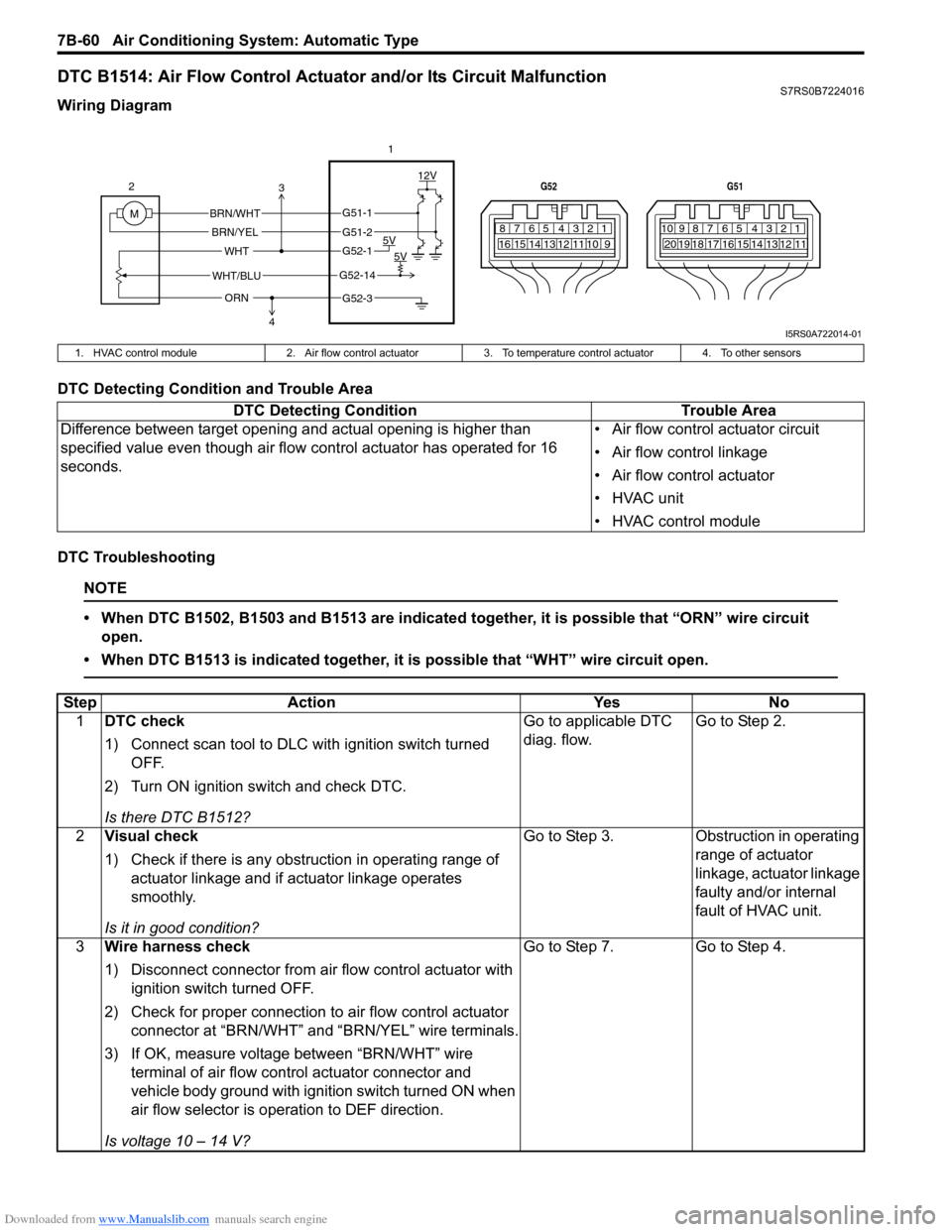
DTC B1514: Air Flow Control Actuator and/or Its Circuit MalfunctionS7RS0B7224016
Wiring Diagram
DTC Detecting Condition and Trouble Area
DTC Troubleshooting
NOTE
• When DTC B1502, B1503 and B1513 are indicated together, it is possible that “ORN” wire circuit open.
• When DTC B1513 is indicated together, it is possible that “WHT” wire circuit open.
7812910
65 431516 14 13 12 11
G52
789101920121112
65 431718 16 15 14 13
G51
M 12V
5V 5V
WHT/BLU
WHT
BRN/WHT
BRN/YEL
2
1
ORN
G51-1
G51-2
G52-1
G52-14
G52-3
3
4
I5RS0A722014-01
1. HVAC control module 2. Air flow control actuator3. To temperature control actuator 4. To other sensors
DTC Detecting Condition Trouble Area
Difference between target opening and actual opening is higher than
specified value even though air flow control actuator has operated for 16
seconds. • Air flow control actuator circuit
• Air flow control linkage
• Air flow control actuator
• HVAC unit
• HVAC control module
Step
Action YesNo
1 DTC check
1) Connect scan tool to DLC with ignition switch turned
OFF.
2) Turn ON ignition switch and check DTC.
Is there DTC B1512? Go to applicable DTC
diag. flow.
Go to Step 2.
2 Visual check
1) Check if there is any obstruction in operating range of
actuator linkage and if actuator linkage operates
smoothly.
Is it in good condition? Go to Step 3.
Obstruction in operating
range of actuator
linkage, actuator linkage
faulty and/or internal
fault of HVAC unit.
3 Wire harness check
1) Disconnect connector from air flow control actuator with
ignition switch turned OFF.
2) Check for proper connection to air flow control actuator
connector at “BRN/WHT” and “BRN/YEL” wire terminals.
3) If OK, measure voltage between “BRN/WHT” wire terminal of air flow control actuator connector and
vehicle body ground with ignition switch turned ON when
air flow selector is operation to DEF direction.
Is voltage 10 – 14 V? Go to Step 7.
Go to Step 4.
Page 1009 of 1496
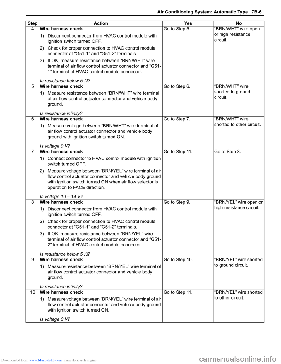
Downloaded from www.Manualslib.com manuals search engine Air Conditioning System: Automatic Type 7B-61
4Wire harness check
1) Disconnect connector from HVAC control module with
ignition switch turned OFF.
2) Check for proper connection to HVAC control module connector at “G51-1” and “G51-2” terminals.
3) If OK, measure resistance between “BRN/WHT” wire terminal of air flow contro l actuator connector and “G51-
1” terminal of HVAC control module connector.
Is resistance below 5
Ω? Go to Step 5. “BRN/WHT” wire open
or high resistance
circuit.
5 Wire harness check
1) Measure resistance between “BRN/WHT” wire terminal
of air flow control actuator connector and vehicle body
ground.
Is resistance infinity? Go to Step 6.
“BRN/WHT” wire
shorted to ground
circuit.
6 Wire harness check
1) Measure voltage between “BRN/WHT” wire terminal of
air flow control actuator connector and vehicle body
ground with ignition switch turned ON.
Is voltage 0 V? Go to Step 7.
“BRN/WHT” wire
shorted to other circuit.
7 Wire harness check
1) Connect connector to HVAC control module with ignition
switch turned OFF.
2) Measure voltage between “BRN/YEL” wire terminal of air flow control actuator connector and vehicle body ground
with ignition switch turned ON when air flow selector is
operation to FACE direction.
Is voltage 10 – 14 V? Go to Step 11. Go to Step 8.
8 Wire harness check
1) Disconnect connector from HVAC control module with
ignition switch turned OFF.
2) Check for proper connection to HVAC control module connector at “G51-1” and “G51-2” terminals.
3) If OK, measure resistance between “BRN/YEL” wire terminal of air flow contro l actuator connector and “G51-
2” terminal of HVAC control module connector.
Is resistance below 5
Ω? Go to Step 9. “BRN/YEL” wire open or
high resistance circuit.
9 Wire harness check
1) Measure resistance between “BRN/YEL” wire terminal of
air flow control actuator connector and vehicle body
ground.
Is resistance infinity? Go to Step 10. “BRN/YEL” wire shorted
to ground circuit.
10 Wire harness check
1) Measure voltage between “BRN/YEL” wire terminal of air
flow control actuator connector and vehicle body ground
with ignition switch turned ON.
Is voltage 0 V? Go to Step 11. “BRN/YEL” wire shorted
to other circuit.
Step Action Yes No
Page 1010 of 1496
Downloaded from www.Manualslib.com manuals search engine 7B-62 Air Conditioning System: Automatic Type
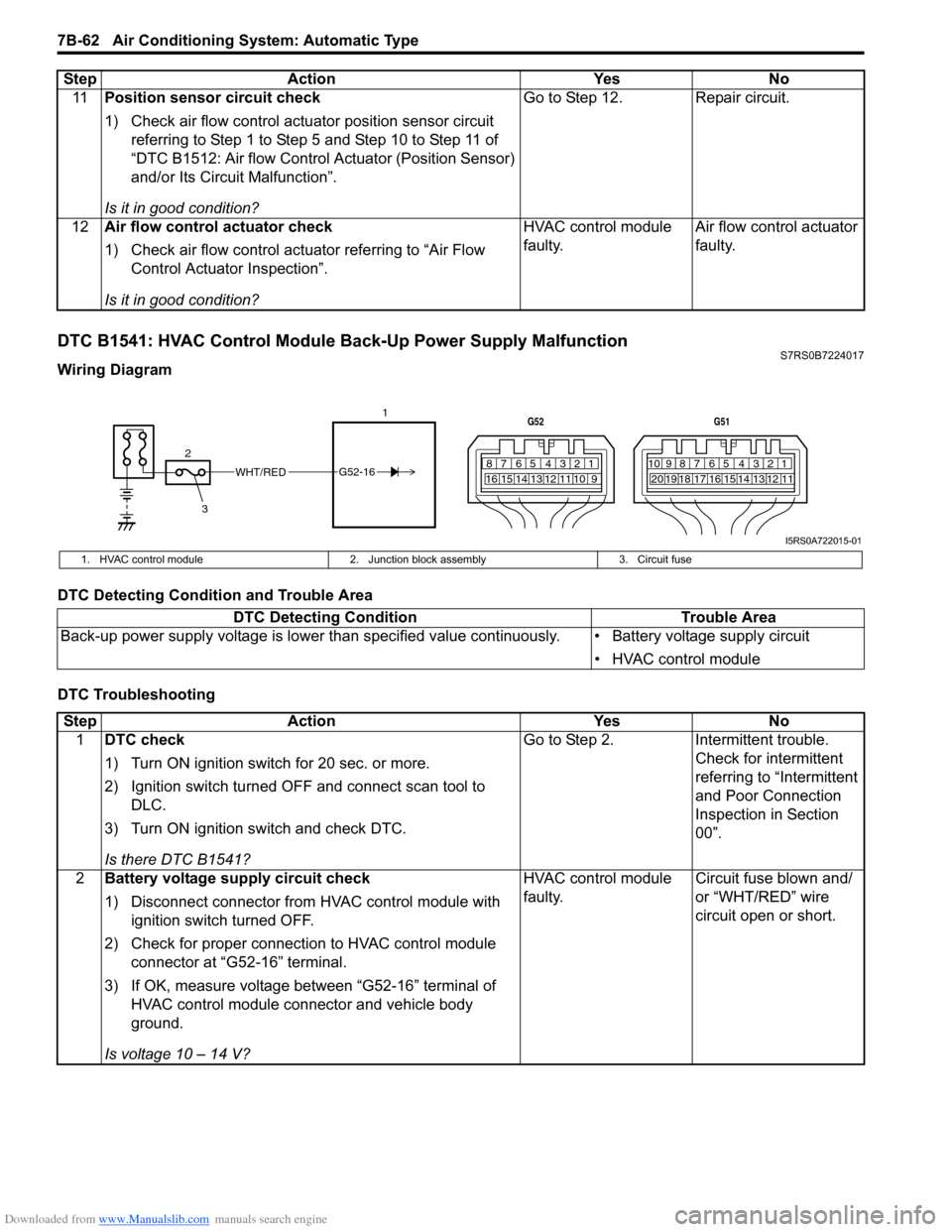
DTC B1541: HVAC Control Module Back-Up Power Supply MalfunctionS7RS0B7224017
Wiring Diagram
DTC Detecting Condition and Trouble Area
DTC Troubleshooting11
Position sensor circuit check
1) Check air flow control actuator position sensor circuit
referring to Step 1 to Step 5 and Step 10 to Step 11 of
“DTC B1512: Air flow Control Actuator (Position Sensor)
and/or Its Circuit Malfunction”.
Is it in good condition? Go to Step 12. Repair circuit.
12 Air flow control actuator check
1) Check air flow control actuator referring to “Air Flow
Control Actuator Inspection”.
Is it in good condition? HVAC control module
faulty.
Air flow control actuator
faulty.
Step Action Yes No
WHT/RED
2 17812910
65 431516 14 13 12 11
G52
789101920121112
65 431718 16 15 14 13
G51
3
G52-16
I5RS0A722015-01
1. HVAC control module
2. Junction block assembly 3. Circuit fuse
DTC Detecting Condition Trouble Area
Back-up power supply voltage is lo wer than specified value continuously. • Battery voltage supply circuit
• HVAC control module
StepAction YesNo
1 DTC check
1) Turn ON ignition switch for 20 sec. or more.
2) Ignition switch turned OF F and connect scan tool to
DLC.
3) Turn ON ignition switch and check DTC.
Is there DTC B1541? Go to Step 2.
Intermittent trouble.
Check for intermittent
referring to “Intermittent
and Poor Connection
Inspection in Section
00”.
2 Battery voltage supply circuit check
1) Disconnect connector from HVAC control module with
ignition switch turned OFF.
2) Check for proper connection to HVAC control module connector at “G52-16” terminal.
3) If OK, measure voltage between “G52-16” terminal of HVAC control module connector and vehicle body
ground.
Is voltage 10 – 14 V? HVAC control module
faulty.
Circuit fuse blown and/
or “WHT/RED” wire
circuit open or short.
Page 1012 of 1496
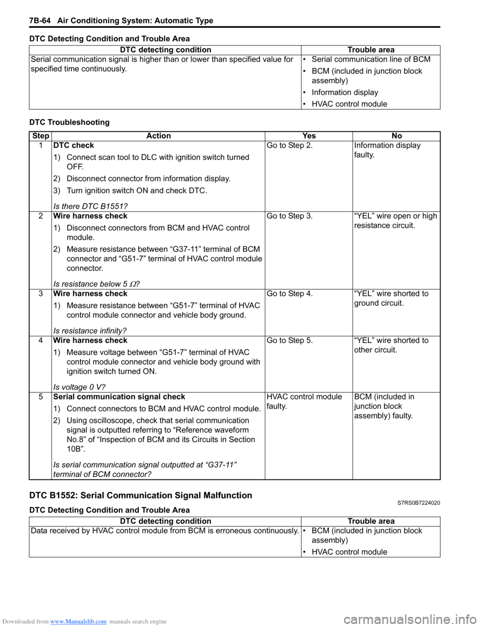
Downloaded from www.Manualslib.com manuals search engine 7B-64 Air Conditioning System: Automatic Type
DTC Detecting Condition and Trouble Area
DTC Troubleshooting
DTC B1552: Serial Communication Signal MalfunctionS7RS0B7224020
DTC Detecting Condition and Trouble AreaDTC detecting condition Trouble area
Serial communication signal is higher than or lower than specified value for
specified time continuously. • Serial communication line of BCM
• BCM (included in junction block
assembly)
• Information display
• HVAC control module
Step Action YesNo
1 DTC check
1) Connect scan tool to DLC with ignition switch turned
OFF.
2) Disconnect connector from information display.
3) Turn ignition switch ON and check DTC.
Is there DTC B1551? Go to Step 2.
Information display
faulty.
2 Wire harness check
1) Disconnect connectors from BCM and HVAC control
module.
2) Measure resistance between “G37-11” terminal of BCM connector and “G51-7” terminal of HVAC control module
connector.
Is resistance below 5
Ω? Go to Step 3. “YEL” wire open or high
resistance circuit.
3 Wire harness check
1) Measure resistance between “G51-7” terminal of HVAC
control module connector and vehicle body ground.
Is resistance infinity? Go to Step 4. “YEL” wire shorted to
ground circuit.
4 Wire harness check
1) Measure voltage between “G51-7” terminal of HVAC
control module connector and vehicle body ground with
ignition switch turned ON.
Is voltage 0 V? Go to Step 5. “YEL” wire shorted to
other circuit.
5 Serial communication signal check
1) Connect connectors to BCM and HVAC control module.
2) Using oscilloscope, check that serial communication
signal is outputted referring to “Reference waveform
No.8” of “Inspection of BCM and its Circuits in Section
10B”.
Is serial communication signal outputted at “G37-11”
terminal of BCM connector? HVAC control module
faulty.
BCM (included in
junction block
assembly) faulty.
DTC detecting condition
Trouble area
Data received by HVAC control module from BCM is erroneous continuously. • BCM (included in junction block assembly)
• HVAC control module
Page 1172 of 1496
Downloaded from www.Manualslib.com manuals search engine 9A-1 Wiring Systems:
Body, Cab and Accessories
Wiring Systems
Precautions
Cautions in Body Electrical System ServicingS7RS0B9100001
When servicing the electric systems, observe the cautions described in “Precautions for Electrical Circuit Service in
Section 00” to protect electrical parts and to prevent a fire.
General Description
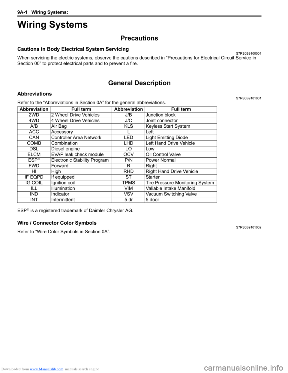
AbbreviationsS7RS0B9101001
Refer to the “Abbreviations in Sect ion 0A” for the general abbreviations.
ESP
® is a registered trademark of Daimler Chrysler AG.
Wire / Connector Color SymbolsS7RS0B9101002
Refer to “Wire Color Sy mbols in Section 0A”.
Abbreviation Full term Abbreviation Full term
2WD 2 Wheel Drive Vehicles J/B Junction block
4WD 4 Wheel Drive Vehicles J/C Joint connectorA/B Air Bag KLS Keyless Start System
ACC Accessory L Left
CAN Controller Area Network LED Light Emitting Diode
COMB Combination LHD Left Hand Drive Vehicle DSL Diesel engine LO Low
ELCM EVAP leak check module OCV Oil Control Valve ESP
®Electronic Stability Program P/N Power Normal
FWD Forward R Right HI High RHD Right Hand Drive Vehicle
IF EQPD If equipped ST Starter IG COIL Ignition coil TPMS Tire Pressure Monitoring System ILL Illumination VIM Valiable Intake Manifold
IND Indicator VSV Vacuum Switching Valve INT Intermittent 5 dr 5 door