Harness SUZUKI SWIFT 2005 2.G Service Manual PDF
[x] Cancel search | Manufacturer: SUZUKI, Model Year: 2005, Model line: SWIFT, Model: SUZUKI SWIFT 2005 2.GPages: 1496, PDF Size: 34.44 MB
Page 611 of 1496
Downloaded from www.Manualslib.com manuals search engine Electronic Stability Program: 4F-37
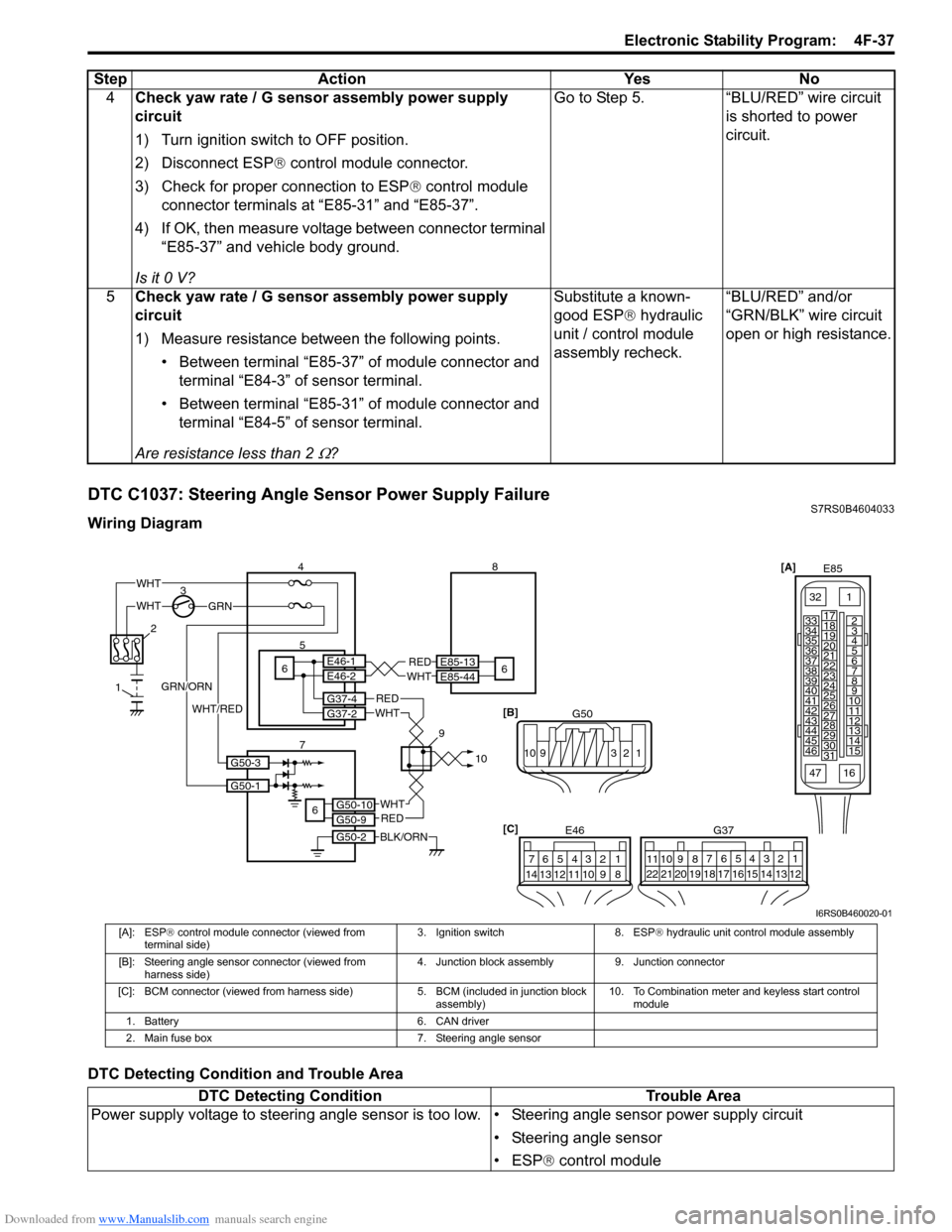
DTC C1037: Steering Angle Sensor Power Supply FailureS7RS0B4604033
Wiring Diagram
DTC Detecting Condition and Trouble Area4
Check yaw rate / G sensor assembly power supply
circuit
1) Turn ignition switch to OFF position.
2) Disconnect ESP ® control module connector.
3) Check for proper connection to ESP ® control module
connector terminals at “E85-31” and “E85-37”.
4) If OK, then measure voltage between connector terminal “E85-37” and vehicle body ground.
Is it 0 V? Go to Step 5. “BLU/RED” wire circuit
is shorted to power
circuit.
5 Check yaw rate / G sensor assembly power supply
circuit
1) Measure resistance between the following points.
• Between terminal “E85-37” of module connector and terminal “E84-3” of sensor terminal.
• Between terminal “E85-31” of module connector and terminal “E84-5” of sensor terminal.
Are resistance less than 2
Ω? Substitute a known-
good ESP
® hydraulic
unit / control module
assembly recheck. “BLU/RED” and/or
“GRN/BLK” wire circuit
open or high resistance.
Step
Action YesNo
[A]
E85
161
15
2
3
4
5
6
7
8
9
10
11
12
13
14
17
18
19
20
21
22
23
24
25
26
27
28
29
30
31
3233
34
35
36
37
38
39
40
41
42
43
44
45
46
47
[C] G37
E46
124
53
67
891011121314124
53
67
891011
1213141516171819202122
WHTGRN
3
E85-13
E85-44REDWHT65E46-1E46-2
4 8
6
BLK/ORN
REDWHT
REDWHT
G37-4G37-2
G50-10G50-9
G50-2
6
2
1
7 910
G50-1
G50-3
GRN/ORN
WHT/RED
WHT
[B]
G50
109 321
I6RS0B460020-01
[A]: ESP® control module connector (viewed from
terminal side) 3. Ignition switch 8. ESP
® hydraulic unit control module assembly
[B]: Steering angle sensor connector (viewed from harness side) 4. Junction block assembly 9. Junction connector
[C]: BCM connector (viewed from harnes s side) 5. BCM (included in junction block
assembly) 10. To Combination meter and keyless start control
module
1. Battery 6. CAN driver
2. Main fuse box 7. Steering angle sensor
DTC Detecting Condition Trouble Area
Power supply voltage to steering angle sensor is to o low. • Steering angle sensor power supply circuit
• Steering angle sensor
• ESP® control module
Page 618 of 1496
Downloaded from www.Manualslib.com manuals search engine 4F-44 Electronic Stability Program:
DTC Troubleshooting
DTC 1071: ESP® Control Module Internal DefectS7RS0B4604056
DTC Detecting Condition and Trouble Area
DTC Troubleshooting
1) Turn ignition switch to OFF position.
2) Check for proper connection from harness to ESP ® control module.
3) If OK, substitute an ESP ® hydraulic unit / control module assembly with correct part number.
4) Recheck system.
Step
Action YesNo
1 Was “Electronic Stability Pr ogram Check” performed? Go to Step 2.Go to “Electronic
Stability Program
System Check”.
2 Check power supply circuit from battery
1) Check battery voltage.
Is it about 11 V or higher? Go to Step 3.
Check charging system
referring to “Battery
Inspection in Section
1J” and “Generator Test
(Undercharged Battery
Check) in Section 1J”.
3 Check fuse
1) Check main fuse for solenoid and its terminal.
Is it in good condition? Go to Step 4.
Replace fuse and check
for short circuit to
ground.
4 Check solenoid valve power supply circuit
1) Turn ignition switch to OFF position.
2) Disconnect control module connector.
3) Check for proper connection to ESP® control module at
terminal “E85-1”.
4) If OK, then measure voltage between connector terminal “E85-1” and vehicle body ground.
Is it 10 – 14 V? Substitute a known-
good ESP
® hydraulic
unit / control module
assembly and recheck. “WHT/BLU” circuit
imperfect short to
ground.
DTC Detecting Condition
Trouble Area
ESP ® control module internal defect is detected. • ESP ® control module
Page 619 of 1496
Downloaded from www.Manualslib.com manuals search engine Electronic Stability Program: 4F-45
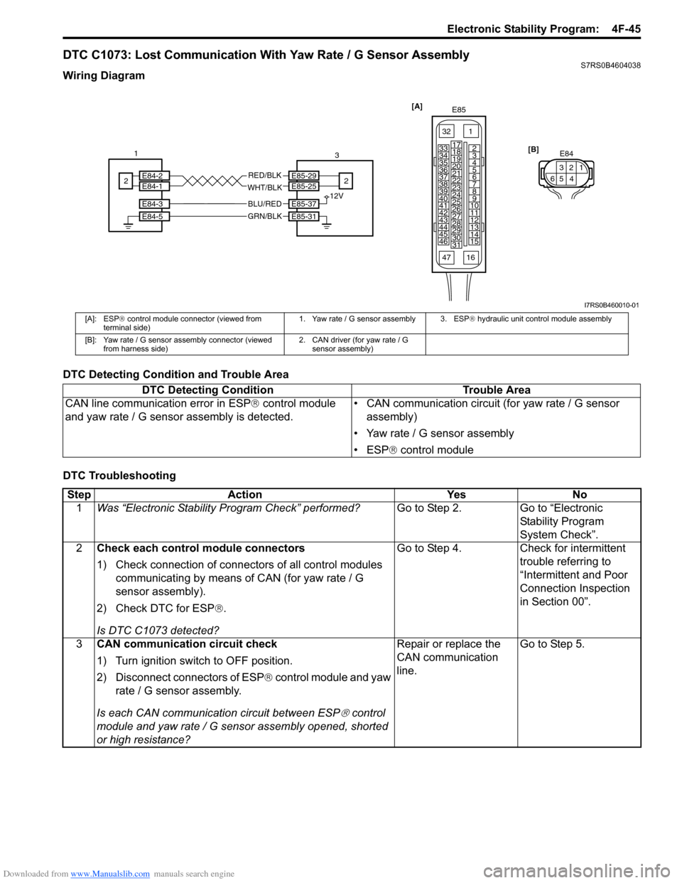
DTC C1073: Lost Communication With Yaw Rate / G Sensor AssemblyS7RS0B4604038
Wiring Diagram
DTC Detecting Condition and Trouble Area
DTC Troubleshooting
[A]E85
161
15
2
3
4
5
6
7
8
9
10
11
12
13
14
17
18
19
20
21
22
23
24
25
26
27
28
29
30
31
3233
34
35
36
37
38
39
40
41
42
43
44
45
46
47
E85-29E85-25
E85-37
E85-31
E84-3
E84-5
E84-2E84-1 12V
GRN/BLK
BLU/RED
WHT/BLK
RED/BLK [B]
E843
521
46
1
2 3
2
I7RS0B460010-01
[A]: ESP ® control module connector (viewed from
terminal side) 1. Yaw rate / G sensor assembly 3. ESP
® hydraulic unit control module assembly
[B]: Yaw rate / G sensor assembly connector (viewed from harness side) 2. CAN driver (for yaw rate / G
sensor assembly)
DTC Detecting Condition Trouble Area
CAN line communication error in ESP ® control module
and yaw rate / G sensor assembly is detected. • CAN communication circuit (for yaw rate / G sensor
assembly)
• Yaw rate / G sensor assembly
• ESP ® control module
Step Action YesNo
1 Was “Electronic Stability Pr ogram Check” performed? Go to Step 2.Go to “Electronic
Stability Program
System Check”.
2 Check each control module connectors
1) Check connection of connectors of all control modules
communicating by means of CAN (for yaw rate / G
sensor assembly).
2) Check DTC for ESP ®.
Is DTC C1073 detected? Go to Step 4.
Check for intermittent
trouble referring to
“Intermittent and Poor
Connection Inspection
in Section 00”.
3 CAN communication circuit check
1) Turn ignition switch to OFF position.
2) Disconnect connectors of ESP ® control module and yaw
rate / G sensor assembly.
Is each CAN communicati on circuit between ESP
® control
module and yaw rate / G sensor assembly opened, shorted
or high resistance? Repair or replace the
CAN communication
line.
Go to Step 5.
Page 623 of 1496
Downloaded from www.Manualslib.com manuals search engine Electronic Stability Program: 4F-49
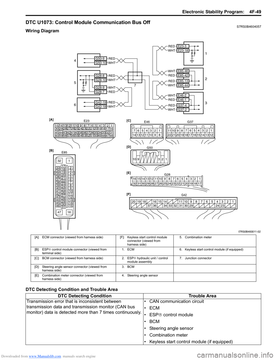
DTC U1073: Control Module Communication Bus OffS7RS0B4604057
Wiring Diagram
DTC Detecting Condition and Trouble Area
E85-13E85-44
E46-2E46-1
G37-4G37-2
E85-46E85-42
E23-3E23-18
G50-9G50-10
G28-8G28-10
G28-9G28-7
G42-19G42-18
REDWHT
WHTRED
WHTRED
REDWHT
REDWHT
WHTRED
REDWHT
REDWHT
REDWHT
[A]
21
E2334
1819
5671011
17
20
47 46
495051
2122
52 16
25 9
24
14
29
5557 54 53
59
60 5826
27
28
15
30
56 4832 31343536374042 39 38
44
45 43 41 33
1213
238
G42[F]
1234567891011
141516
36 34 33 32 31 30 29 24 23
37
181920
[B]
E85
161
15
2
3
4
5
6
7
8
9
10
11
12
13
14
17
18
19
20
21
22
23
24
25
26
27
28
29
30
31
3233
34
35
36
37
38
39
40
41
42
43
44
45
46
47 [C]
G37
E46
124
53
67
891011121314124
53
67
891011
1213141516171819202122
[E] G28
12345678910111213141516
17181920212223242526272829303132
[D] G50
109 321
4
5
7 1
2
3
6
I7RS0B460011-02
[A]: ECM connector (viewed from harness side) [F]: Keyless start control module
connector (viewed from
harness side) 5. Combination meter
[B]: ESP ® control module connector (viewed from
terminal side) 1. ECM
6. Keyless start control module (if equipped)
[C]: BCM connector (viewed from harness side) 2. ESP® hydraulic unit / control
module assembly 7. Junction connector
[D]: Steering angle sensor connector (viewed from harness side) 3. BCM
[E]: Combination meter connector (viewed from harness side) 4. Steering angle sensor
DTC Detecting Condition
Trouble Area
Transmission error that is inconsistent between
transmission data and transmission monitor (CAN bus
monitor) data is detected more than 7 times continuously. • CAN communication circuit
•ECM
• ESP
® control module
•BCM
• Steering angle sensor
• Combination meter
• Keyless start control module (if equipped)
Page 632 of 1496
Downloaded from www.Manualslib.com manuals search engine 4F-58 Electronic Stability Program:
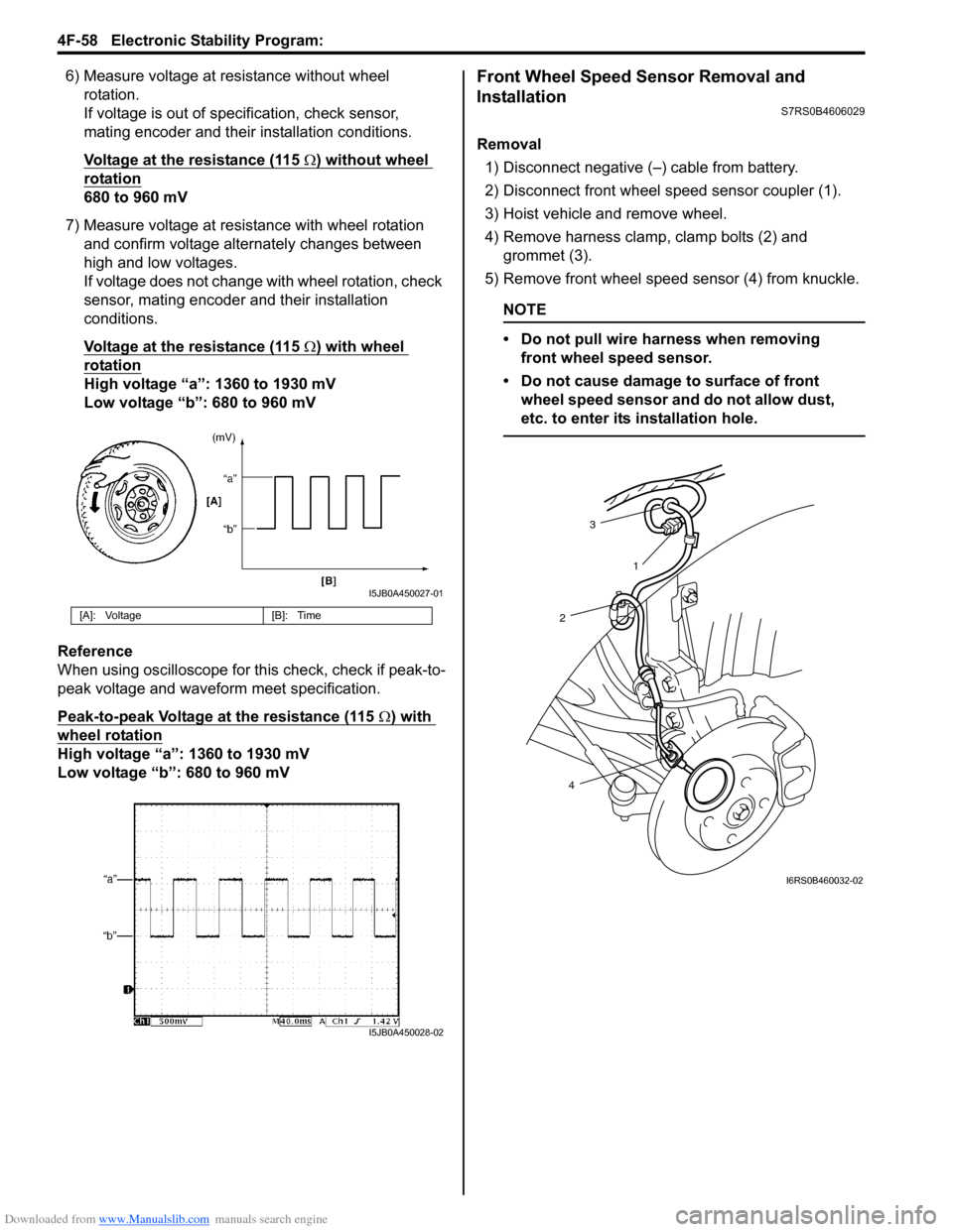
6) Measure voltage at resistance without wheel rotation.
If voltage is out of specification, check sensor,
mating encoder and their installation conditions.
Voltage at the resistance (115
Ω) without wheel
rotation
680 to 960 mV
7) Measure voltage at resistance with wheel rotation and confirm voltage alternately changes between
high and low voltages.
If voltage does not change with wheel rotation, check
sensor, mating encoder and their installation
conditions.
Voltage at the resistance (115
Ω) with wheel
rotation
High voltage “a”: 1360 to 1930 mV
Low voltage “b”: 680 to 960 mV
Reference
When using oscilloscope for this check, check if peak-to-
peak voltage and waveform meet specification.
Peak-to-peak Voltage at the resistance (115
Ω) with
wheel rotation
High voltage “a”: 1360 to 1930 mV
Low voltage “b”: 680 to 960 mV
Front Wheel Speed Sensor Removal and
Installation
S7RS0B4606029
Removal
1) Disconnect negative (–) cable from battery.
2) Disconnect front wheel speed sensor coupler (1).
3) Hoist vehicle and remove wheel.
4) Remove harness clamp, clamp bolts (2) and grommet (3).
5) Remove front wheel speed sensor (4) from knuckle.
NOTE
• Do not pull wire harness when removing front wheel speed sensor.
• Do not cause damage to surface of front wheel speed sensor and do not allow dust,
etc. to enter its installation hole.
[A]: Voltage [B]: Time
I5JB0A450027-01
I5JB0A450028-02
3
2
4 1
I6RS0B460032-02
Page 633 of 1496
Downloaded from www.Manualslib.com manuals search engine Electronic Stability Program: 4F-59
Installation
CAUTION!
Do not pull or twist wire harness more than
necessary when installing front wheel speed
sensor.
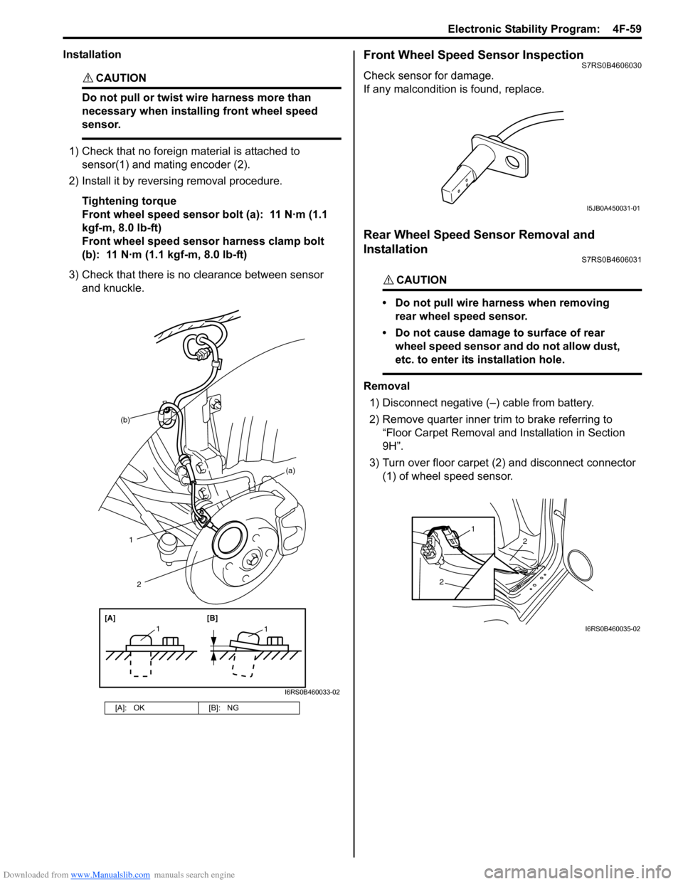
1) Check that no foreign material is attached to sensor(1) and mating encoder (2).
2) Install it by reversing removal procedure.
Tightening torque
Front wheel speed sensor bolt (a): 11 N·m (1.1
kgf-m, 8.0 lb-ft)
Front wheel speed sensor harness clamp bolt
(b): 11 N·m (1.1 kgf-m, 8.0 lb-ft)
3) Check that there is no clearance between sensor and knuckle.
Front Wheel Speed Sensor InspectionS7RS0B4606030
Check sensor for damage.
If any malcondition is found, replace.
Rear Wheel Speed Sensor Removal and
Installation
S7RS0B4606031
CAUTION!
• Do not pull wire harness when removing rear wheel speed sensor.
• Do not cause damage to surface of rear wheel speed sensor and do not allow dust,
etc. to enter its installation hole.
Removal
1) Disconnect negative (–) cable from battery.
2) Remove quarter inner trim to brake referring to
“Floor Carpet Removal and Installation in Section
9H”.
3) Turn over floor carpet (2) and disconnect connector (1) of wheel speed sensor.
[A]: OK [B]: NG
(b)
1
[A][B]
11
2
(a)
I6RS0B460033-02
I5JB0A450031-01
2
2
1
I6RS0B460035-02
Page 634 of 1496
Downloaded from www.Manualslib.com manuals search engine 4F-60 Electronic Stability Program:
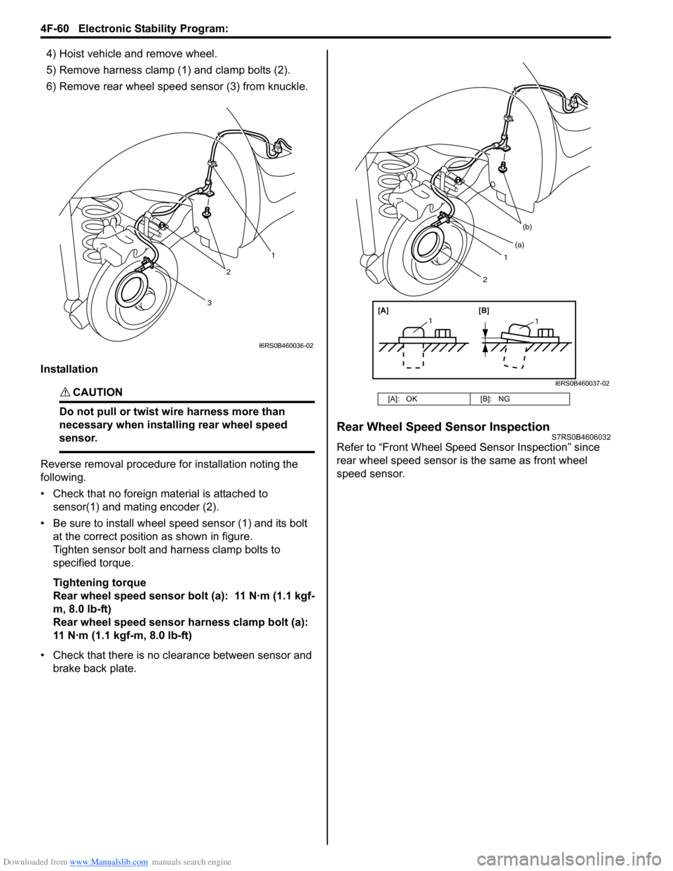
4) Hoist vehicle and remove wheel.
5) Remove harness clamp (1) and clamp bolts (2).
6) Remove rear wheel speed sensor (3) from knuckle.
Installation
CAUTION!
Do not pull or twist wi re harness more than
necessary when installing rear wheel speed
sensor.
Reverse removal procedure for installation noting the
following.
• Check that no foreign material is attached to sensor(1) and mating encoder (2).
• Be sure to install wheel speed sensor (1) and its bolt at the correct position as shown in figure.
Tighten sensor bolt and harness clamp bolts to
specified torque.
Tightening torque
Rear wheel speed sensor bolt (a): 11 N·m (1.1 kgf-
m, 8.0 lb-ft)
Rear wheel speed sensor harness clamp bolt (a):
11 N·m (1.1 kgf-m, 8.0 lb-ft)
• Check that there is no clearance between sensor and brake back plate.
Rear Wheel Speed Sensor InspectionS7RS0B4606032
Refer to “Front Wheel Speed Sensor Inspection” since
rear wheel speed sensor is the same as front wheel
speed sensor.
3
2
1
I6RS0B460036-02
[A]: OK [B]: NG
1
(b)
[A][B]
11
(a)
2
I6RS0B460037-02
Page 638 of 1496
Downloaded from www.Manualslib.com manuals search engine 4F-64 Electronic Stability Program:
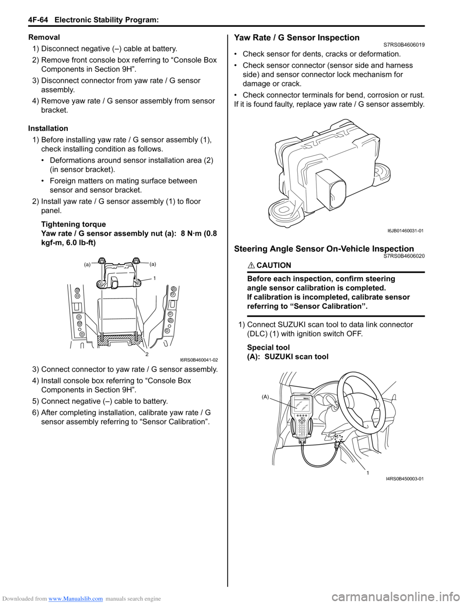
Removal1) Disconnect negative (–) cable at battery.
2) Remove front console box referring to “Console Box Components in Section 9H”.
3) Disconnect connector from yaw rate / G sensor
assembly.
4) Remove yaw rate / G sens or assembly from sensor
bracket.
Installation 1) Before installing yaw rate / G sensor assembly (1),
check installing condition as follows.
• Deformations around sensor installation area (2) (in sensor bracket).
• Foreign matters on mating surface between sensor and sensor bracket.
2) Install yaw rate / G sensor assembly (1) to floor panel.
Tightening torque
Yaw rate / G sensor assembly nut (a): 8 N·m (0.8
kgf-m, 6.0 lb-ft)
3) Connect connector to yaw rate / G sensor assembly.
4) Install console box referring to “Console Box Components in Section 9H”.
5) Connect negative (–) cable to battery.
6) After completing installation, calibrate yaw rate / G
sensor assembly referring to “Sensor Calibration”.Yaw Rate / G Sensor InspectionS7RS0B4606019
• Check sensor for dents, cracks or deformation.
• Check sensor connector (sensor side and harness
side) and sensor connector lock mechanism for
damage or crack.
• Check connector terminals for bend, corrosion or rust.
If it is found faulty, replace yaw rate / G sensor assembly.
Steering Angle Sensor On-Vehicle InspectionS7RS0B4606020
CAUTION!
Before each inspection, confirm steering
angle sensor calibration is completed.
If calibration is incompleted, calibrate sensor
referring to “Sensor Calibration”.
1) Connect SUZUKI scan tool to data link connector
(DLC) (1) with ignition switch OFF.
Special tool
(A): SUZUKI scan tool
(a)
1
(a)
2I6RS0B460041-02
I6JB01460031-01
(A)
1
I4RS0B450003-01
Page 639 of 1496
Downloaded from www.Manualslib.com manuals search engine Electronic Stability Program: 4F-65
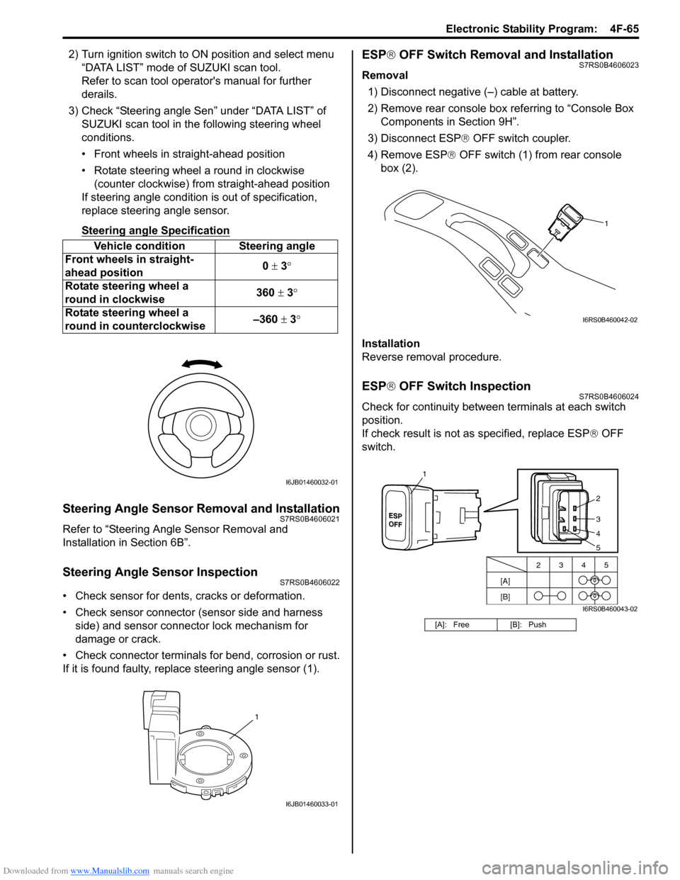
2) Turn ignition switch to ON position and select menu
“DATA LIST” mode of SUZUKI scan tool.
Refer to scan tool operator's manual for further
derails.
3) Check “Steering angle Sen” under “DATA LIST” of SUZUKI scan tool in th e following steering wheel
conditions.
• Front wheels in straight-ahead position
• Rotate steering wheel a round in clockwise (counter clockwise) from straight-ahead position
If steering angle condition is out of specification,
replace steering angle sensor.
Steering angle Specification
Steering Angle Sensor Removal and InstallationS7RS0B4606021
Refer to “Steering Angle Sensor Removal and
Installation in Section 6B”.
Steering Angle Sensor InspectionS7RS0B4606022
• Check sensor for dents, cracks or deformation.
• Check sensor connector (sensor side and harness
side) and sensor connector lock mechanism for
damage or crack.
• Check connector terminals for bend, corrosion or rust.
If it is found faulty, replace steering angle sensor (1).
ESP ® OFF Switch Removal and InstallationS7RS0B4606023
Removal
1) Disconnect negative (–) cable at battery.
2) Remove rear console box referring to “Console Box Components in Section 9H”.
3) Disconnect ESP ® OFF switch coupler.
4) Remove ESP ® OFF switch (1) from rear console
box (2).
Installation
Reverse removal procedure.
ESP ® OFF Switch InspectionS7RS0B4606024
Check for continuity between terminals at each switch
position.
If check result is not as specified, replace ESP ® OFF
switch.
Vehicle condition Steering angle
Front wheels in straight-
ahead position 0
± 3 °
Rotate steering wheel a
round in clockwise 360
± 3°
Rotate steering wheel a
round in counterclockwise –360
± 3 °
I6JB01460032-01
1
I6JB01460033-01
[A]: Free [B]: Push
1
I6RS0B460042-02
[A]
[B]2345
2
3
4
1
5
I6RS0B460043-02
Page 640 of 1496
Downloaded from www.Manualslib.com manuals search engine 4F-66 Electronic Stability Program:
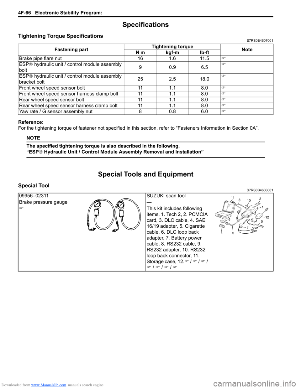
Specifications
Tightening Torque SpecificationsS7RS0B4607001
Reference:
For the tightening torque of fastener not specified in this section, refer to “Fasteners Information in Section 0A”.
NOTE
The specified tightening torque is also described in the following.
“ESP® Hydraulic Unit / Control Module Assembly Removal and Installation”
Special Tools and Equipment
Special ToolS7RS0B4608001
Fastening part Tightening torque
Note
N ⋅mkgf-mlb-ft
Brake pipe flare nut 16 1.6 11.5 �)
ESP ® hydraulic unit / control module assembly
bolt 90.9 6.5�)
ESP ® hydraulic unit / control module assembly
bracket bolt 25 2.5 18.0�)
Front wheel speed sensor bolt 11 1.1 8.0 �)
Front wheel speed sensor harness clamp bolt 11 1.1 8.0 �)
Rear wheel speed sensor bolt 11 1.1 8.0 �)
Rear wheel speed sensor har ness clamp bolt 11 1.1 8.0 �)
Yaw rate / G sensor assembly nut 8 0.8 6.0 �)
09956–02311SUZUKI scan tool
Brake pressure gauge —
�) This kit includes following
items. 1. Tech 2, 2. PCMCIA
card, 3. DLC cable, 4. SAE
16/19 adapter, 5. Cigarette
cable, 6. DLC loop back
adapter, 7. Battery power
cable, 8. RS232 cable, 9.
RS232 adapter, 10. RS232
loop back connector, 11.
Storage case, 12.�) / �) / �) /
�) / �) / �) / �)