auto lock SUZUKI SWIFT 2005 2.G Service Manual Online
[x] Cancel search | Manufacturer: SUZUKI, Model Year: 2005, Model line: SWIFT, Model: SUZUKI SWIFT 2005 2.GPages: 1496, PDF Size: 34.44 MB
Page 1216 of 1496

Downloaded from www.Manualslib.com manuals search engine 9A-45 Wiring Systems:
System Circuit Diagram
System Circuit DiagramS7RS0B910E001
Refer to “A-1 Cranking System Circuit Diagram”.
Refer to “A-2 Charging System Circuit Diagram”.
Refer to “A-3 Ignition System Circuit Diagram”.
Refer to “A-4 Cooling System Circuit Diagram”.
Refer to “A-5 Engine and A/C Control System Circuit Diagram”.
Refer to “A-6 A/T Control System Circuit Diagram”.
Refer to “A-7 Immobilizer System Circuit Diagram”.
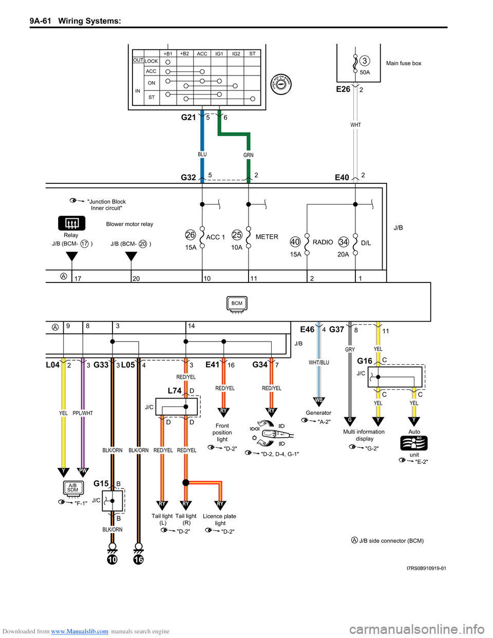
Refer to “A-8 Body Control System Circuit Diagram”.
Refer to “B-1 Windshield Wiper and Washer Circuit Diagram”.
Refer to “B-2 Rear Wiper and Washer Circuit Diagram”.
Refer to “B-3 Rear Defogger Circuit Diagram”.
Refer to “B-4 Power Window Circuit Diagram”.
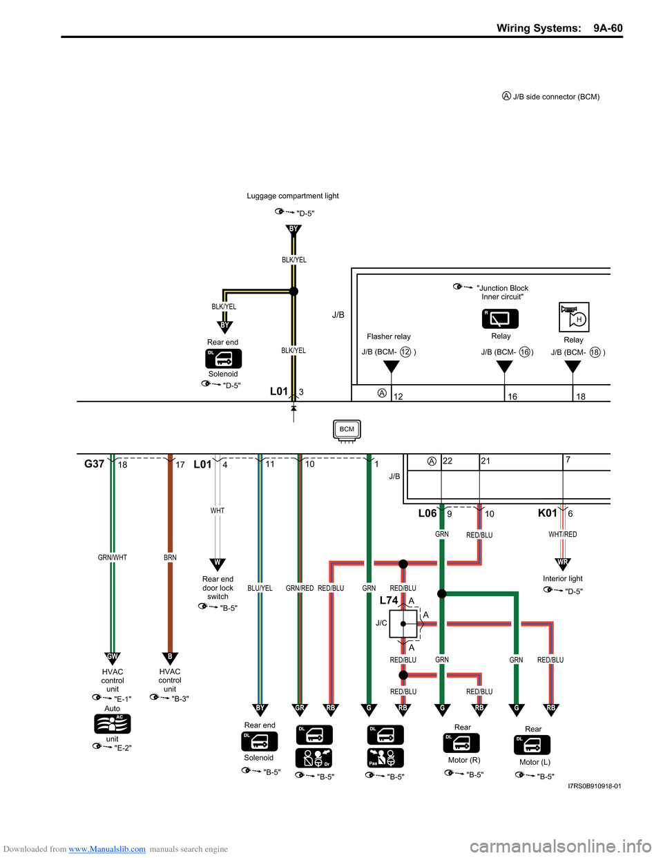
Refer to “B-5 Power Door Lock Circuit Diagram”.
Refer to “B-6 Power Mi rror Circuit Diagram”.
Refer to “B-7 Horn Circuit Diagram”.
Refer to “B-8 Seat Heater Circuit Diagram”.
Refer to “B-9 Keyless Star t System Circuit Diagram”.
Refer to “C-1 Combination Me ter Circuit Diagram (Meter)”.
Refer to “C-2 Combination Mete r Circuit Diagram (Indicator)”.
Refer to “C-3 Combination Meter Circuit Diagram (Warning Light)”.
Refer to “D-1 Headlight System Circuit Diagram”.
Refer to “D-2 Position, Tail and Licence Plate Light System Circuit Diagram”.
Refer to “D-3 Front Fog Light System Circuit Diagram”.
Refer to “D-4 Illumination Light System Circuit Diagram”.
Refer to “D-5 Interior Li ght System Circuit Diagram”.
Refer to “D-6 Turn Signal and Hazard Warning Light System Circuit Diagram”.
Refer to “D-7 Brake Light System Circuit Diagram”.
Refer to “D-8 Back-Up Light System Circuit Diagram”.
Refer to “D-9 Headlight Beam Leveling System Circuit Diagram”.
Refer to “D-10 Rear Fog Light Circuit Diagram”.
Refer to “E-1 Heater System Circuit Diagram”.
Refer to “E-2 Auto A/C System Circuit Diagram”.
Refer to “F-1 Air-Bag System Circuit Diagram”.
Refer to “F-2 Anti-Lock Brake System Circuit Diagram”.
Refer to “F-3 Electronic Stabilit y Program System Circuit Diagram”.
Refer to “F-4 Power Steeri ng System Circuit Diagram”.
Refer to “G-1 Audio Sy stem Circuit Diagram”.
Refer to “G-2 Multi Information Display / Accessory Socket System Circuit Diagram”.
Page 1231 of 1496
Downloaded from www.Manualslib.com manuals search engine Wiring Systems: 9A-60
1817
GRN/WHTBRN
"E-1"
"E-2"
HVAC
control unit
Auto
unit
G37
Flasher relay Relay
Relay
H
12
"Junction Block
Inner circuit"
J/B (BCM- 12 )J/B (BCM- 18 )
1618
J/B (BCM- 16 )
J/B
"B-5""B-5""B-5""B-5"
11
9
L06
22
10
21
Rear
J/B
GRN
GRN
RED/BLU
RED/BLURED/BLU
RED/BLUGRNRED/BLU
GRN
110
GRN/REDRED/BLURED/BLUBLU/YEL
Rear end
L014
WHT
Rear end
door lock switch
3
"D-5"
BLK/YEL
L01
Luggage compartment light
7
6K01
Interior light
"D-5"
WHT/RED
WR
J/B side connector (BCM)
A
A
A
BY
GWB
W
BYGRRBGGRBGRBGRB
"B-5"
SolenoidMotor (R)
"B-5"
Rear
Motor (L)
"B-3"
HVAC
control unit
BCM
BLK/YEL
BY
BLK/YEL
"D-5"
Solenoid
Rear end
A
A
A
J/C
L74
I7RS0B910918-01
Page 1232 of 1496
Downloaded from www.Manualslib.com manuals search engine 9A-61 Wiring Systems:
50A
3
J/B
15ARADIO
40
2
15A
ACC 1
26
10
1
20AD/L
34
11
10A
METER
25
Main fuse box
WHT
E402
20
Blower motor relay
"Junction Block Inner circuit"
Relay
J/B (BCM- 20 )J/B (BCM- 17 )
17
2L04
9
3
83
B BG33
3
4L05
10
J/C
G15
BLK/ORN
BLK/ORN
16
BLK/ORN
"F-1"
YELPPL/WHT
A/B
SDM
14
316E417G34
Front
position light
"D-2"
"D-2, D-4, G-1"
J/B
RED/YELRED/YEL
J/C
L74D
DD
Licence plate light
"D-2"
YPW
"A-2"
Generator
E464
WHT/BLU
WB
RYRY
RYRYRY
Tail light
(R)
Tail light
(L)
"D-2"
RED/YEL
RED/YEL
RED/YEL
811
C CG37
J/C
G16
YEL
GRYYEL
GY
C
YEL
Y
"G-2"
Multi information
display Auto
unit
"E-2"
A
A
J/C
2E26
+B1
LOCK
ACC
ON
ST ACC IG1 IG2
STOUT
IN
+B2
BLUGRN
G3252
56G21
J/B side connector (BCM)
A
BCM
I7RS0B910919-01
Page 1341 of 1496
Downloaded from www.Manualslib.com manuals search engine Glass / Windows / Mirrors: 9E-14
Rear End Door Window Defogger Switch
Inspection
S7RS0B9506012
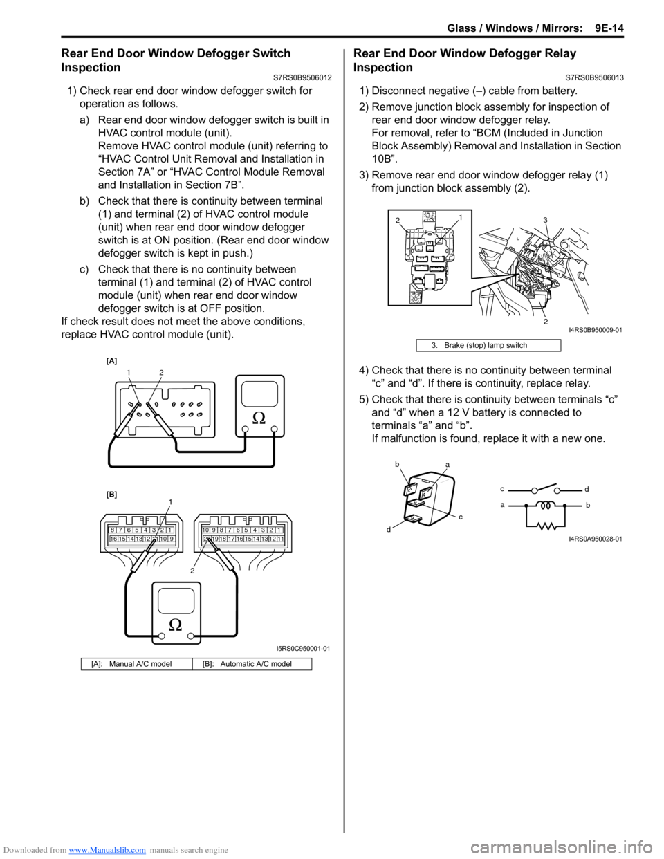
1) Check rear end door window defogger switch for operation as follows.
a) Rear end door window defogger switch is built in HVAC control module (unit).
Remove HVAC control module (unit) referring to
“HVAC Control Unit Removal and Installation in
Section 7A” or “HVAC Control Module Removal
and Installation in Section 7B”.
b) Check that there is continuity between terminal (1) and terminal (2) of HVAC control module
(unit) when rear end door window defogger
switch is at ON position. (Rear end door window
defogger switch is kept in push.)
c) Check that there is no continuity between terminal (1) and terminal (2) of HVAC control
module (unit) when rear end door window
defogger switch is at OFF position.
If check result does not meet the above conditions,
replace HVAC control module (unit).
Rear End Door Window Defogger Relay
Inspection
S7RS0B9506013
1) Disconnect negative (–) cable from battery.
2) Remove junction block assembly for inspection of rear end door window defogger relay.
For removal, refer to “BCM (Included in Junction
Block Assembly) Removal a nd Installation in Section
10B”.
3) Remove rear end door window defogger relay (1) from junction block assembly (2).
4) Check that there is no continuity between terminal “c” and “d”. If there is continuity, replace relay.
5) Check that there is continuity between terminals “c” and “d” when a 12 V battery is connected to
terminals “a” and “b”.
If malfunction is found, replace it with a new one.
[A]: Manual A/C model [B]: Automatic A/C model
12
7812910
65 431516 14 13 12 11789101920121112
65 431718 16 15 14 13
1
2
[A]
[B]
I5RS0C950001-01
3. Brake (stop) lamp switch
1
3
2
2
I4RS0B950009-01
ba
c
dc
a
d
bI4RS0A950028-01
Page 1359 of 1496
Downloaded from www.Manualslib.com manuals search engine Security and Locks: 9F-13
Replacement of Transmitter Battery S7RS0B9606014
If transmitter becomes unreliable, replace transmitter
battery as follows.
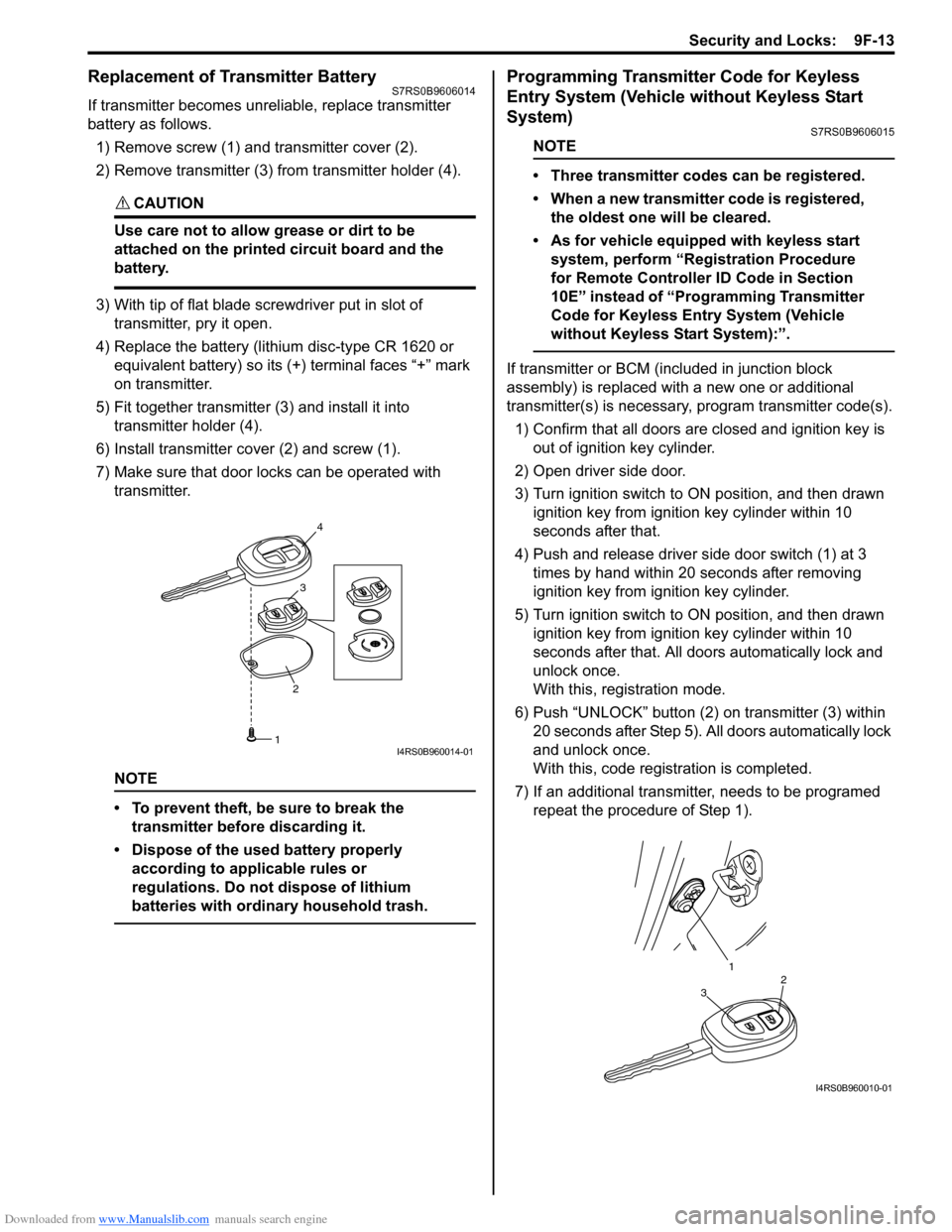
1) Remove screw (1) and transmitter cover (2).
2) Remove transmitter (3) from transmitter holder (4).
CAUTION!
Use care not to allow grease or dirt to be
attached on the printed circuit board and the
battery.
3) With tip of flat blade screwdriver put in slot of transmitter, pry it open.
4) Replace the battery (lithium disc-type CR 1620 or equivalent battery) so its (+) terminal faces “+” mark
on transmitter.
5) Fit together transmitter (3) and install it into
transmitter holder (4).
6) Install transmitter co ver (2) and screw (1).
7) Make sure that door locks can be operated with transmitter.
NOTE
• To prevent theft, be sure to break the transmitter before discarding it.
• Dispose of the used battery properly according to applicable rules or
regulations. Do not dispose of lithium
batteries with ordinary household trash.
Programming Transmitter Code for Keyless
Entry System (Vehicle without Keyless Start
System)
S7RS0B9606015
NOTE
• Three transmitter codes can be registered.
• When a new transmitter code is registered, the oldest one will be cleared.
• As for vehicle equipped with keyless start system, perform “Registration Procedure
for Remote Controller ID Code in Section
10E” instead of “Programming Transmitter
Code for Keyless Entry System (Vehicle
without Keyless Start System):”.
If transmitter or BCM (included in junction block
assembly) is replaced with a new one or additional
transmitter(s) is necessary, program transmitter code(s).
1) Confirm that all doors are closed and ignition key is
out of ignition key cylinder.
2) Open driver side door.
3) Turn ignition switch to ON position, and then drawn ignition key from igniti on key cylinder within 10
seconds after that.
4) Push and release driver side door switch (1) at 3 times by hand within 20 seconds after removing
ignition key from ig nition key cylinder.
5) Turn ignition switch to ON position, and then drawn ignition key from igniti on key cylinder within 10
seconds after that. All d oors automatically lock and
unlock once.
With this, registration mode.
6) Push “UNLOCK” button (2) on transmitter (3) within
20 seconds after Step 5). All doors automatically lock
and unlock once.
With this, code registration is completed.
7) If an additional transmitter, needs to be programed repeat the procedure of Step 1).
23
4
1I4RS0B960014-01
1
32
I4RS0B960010-01
Page 1411 of 1496
Downloaded from www.Manualslib.com manuals search engine Body Electrical Control System: 10B-8
Component Location
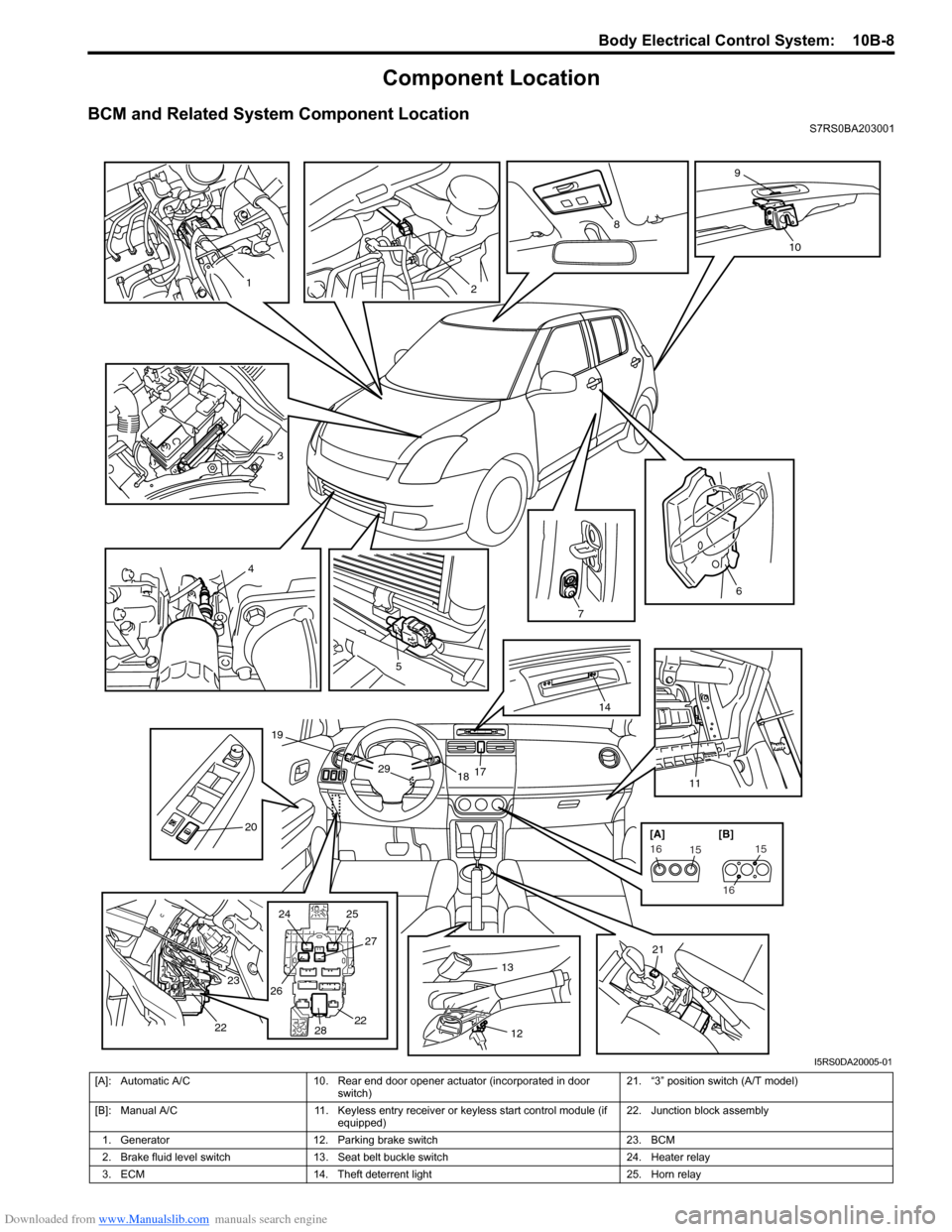
BCM and Related System Component LocationS7RS0BA203001
3
4
5
7
6
1117
1829
19
14
20
21
24
25
26 27
28 22
23
22
1
2
8
9
10
1312
151615
16
[A] [B]
I5RS0DA20005-01
[A]: Automatic A/C
10. Rear end door opener actuator (incorporated in door
switch) 21. “3” position switch (A/T model)
[B]: Manual A/C 11. Keyless entry receiver or keyless start control module (if
equipped) 22. Junction block assembly
1. Generator 12. Parking brake switch 23. BCM
2. Brake fluid level switch 13. Seat belt buckle switch 24. Heater relay
3. ECM 14. Theft deterrent light 25. Horn relay
Page 1442 of 1496
Downloaded from www.Manualslib.com manuals search engine 10B-39 Body Electrical Control System:
Repair Instructions
BCM (Included in Junction Block Assembly)
Removal and Installation
S7RS0BA206001
CAUTION!
Do not attempt removal of BCM from junction
block assembly as it may cause contact
failure.
If there is faulty condition in BCM, replace
junction block assembly.
Removal
1) Disconnect negative (–) cable from battery.
2) Disable air bag system referring to “Disabling Air Bag System in Section 8B”.
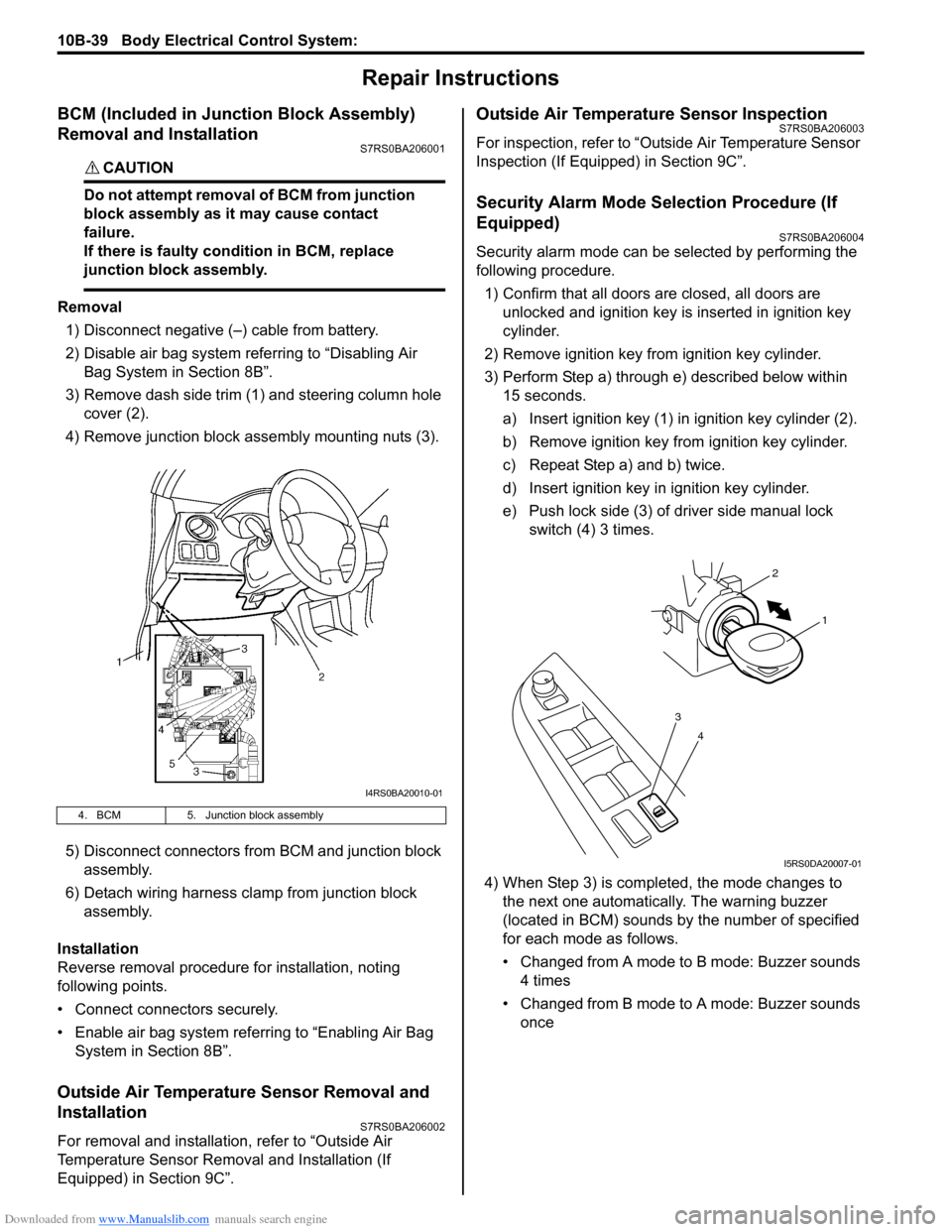
3) Remove dash side trim (1) and steering column hole cover (2).
4) Remove junction block assembly mounting nuts (3).
5) Disconnect connectors from BCM and junction block assembly.
6) Detach wiring harness clamp from junction block assembly.
Installation
Reverse removal procedure for installation, noting
following points.
• Connect connectors securely.
• Enable air bag system referring to “Enabling Air Bag System in Section 8B”.
Outside Air Temperature Sensor Removal and
Installation
S7RS0BA206002
For removal and installation, refer to “Outside Air
Temperature Sensor Removal and Installation (If
Equipped) in Section 9C”.
Outside Air Temperature Sensor InspectionS7RS0BA206003
For inspection, refer to “Outside Air Temperature Sensor
Inspection (If Equipped) in Section 9C”.
Security Alarm Mode Selection Procedure (If
Equipped)
S7RS0BA206004
Security alarm mode can be selected by performing the
following procedure.
1) Confirm that all doors are closed, all doors are unlocked and ignition key is inserted in ignition key
cylinder.
2) Remove ignition key from ignition key cylinder.
3) Perform Step a) through e) described below within 15 seconds.
a) Insert ignition key (1) in ignition key cylinder (2).
b) Remove ignition key from ignition key cylinder.
c) Repeat Step a) and b) twice.
d) Insert ignition key in ignition key cylinder.
e) Push lock side (3) of driver side manual lock switch (4) 3 times.
4) When Step 3) is completed, the mode changes to the next one automatically. The warning buzzer
(located in BCM) sounds by the number of specified
for each mode as follows.
• Changed from A mode to B mode: Buzzer sounds 4 times
• Changed from B mode to A mode: Buzzer sounds once
4. BCM 5. Junction block assembly
I4RS0BA20010-01
4
3
1
2
I5RS0DA20007-01
Page 1453 of 1496
Downloaded from www.Manualslib.com manuals search engine Immobilizer Control System: 10C-10
DTC Confirmation Procedure1) Register the transponder code in the transponder in the ignition key with ECM referring to “Registration of the
Ignition Key”.
2) Check DTC in ECM.
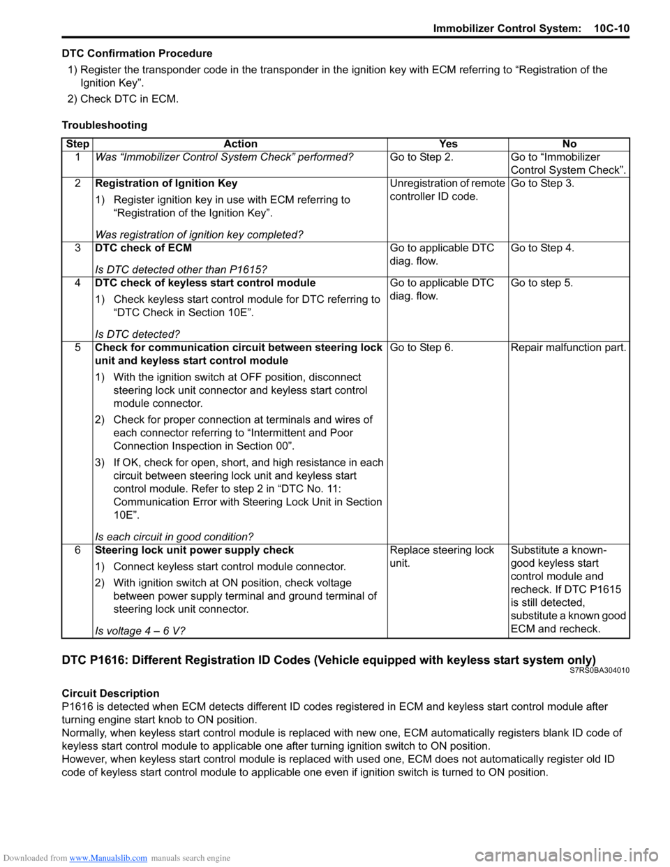
Troubleshooting
DTC P1616: Different Registration ID Codes (Vehicle equipped with keyless start system only)S7RS0BA304010
Circuit Description
P1616 is detected when ECM detects different ID codes registered in ECM and keyless start control module after
turning engine start knob to ON position.
Normally, when keyless start control module is replaced with new one, ECM automatically registers blank ID code of
keyless start control module to applicable one after turning ignition switch to ON position.
However, when keyless start control module is replaced wit h used one, ECM does not automatically register old ID
code of keyless start control module to applicable one ev en if ignition switch is turned to ON position.
Step Action Yes No
1 Was “Immobilizer Control S ystem Check” performed? Go to Step 2. Go to “Immobilizer
Control System Check”.
2 Registration of Ignition Key
1) Register ignition key in use with ECM referring to
“Registration of the Ignition Key”.
Was registration of ignition key completed? Unregistration of remote
controller ID code.
Go to Step 3.
3 DTC check of ECM
Is DTC detected other than P1615? Go to applicable DTC
diag. flow.
Go to Step 4.
4 DTC check of keyless start control module
1) Check keyless start control module for DTC referring to
“DTC Check in Section 10E”.
Is DTC detected? Go to applicable DTC
diag. flow.
Go to step 5.
5 Check for communication circuit between steering lock
unit and keyless start control module
1) With the ignition switch at OFF position, disconnect
steering lock unit connector and keyless start control
module connector.
2) Check for proper connection at terminals and wires of
each connector referring to “Intermittent and Poor
Connection Inspection in Section 00”.
3) If OK, check for open, short, and high resistance in each circuit between steering lock unit and keyless start
control module. Refer to step 2 in “DTC No. 11:
Communication Error with Steeri ng Lock Unit in Section
10E”.
Is each circuit in good condition? Go to Step 6. Repair malfunction part.
6 Steering lock unit power supply check
1) Connect keyless start control module connector.
2) With ignition switch at ON position, check voltage
between power supply terminal and ground terminal of
steering lock unit connector.
Is voltage 4 – 6 V? Replace steering lock
unit.
Substitute a known-
good keyless start
control module and
recheck. If DTC P1615
is still detected,
substitute a known good
ECM and recheck.