spec SUZUKI SWIFT 2005 2.G Service Workshop Manual
[x] Cancel search | Manufacturer: SUZUKI, Model Year: 2005, Model line: SWIFT, Model: SUZUKI SWIFT 2005 2.GPages: 1496, PDF Size: 34.44 MB
Page 1491 of 1496

Downloaded from www.Manualslib.com manuals search engine Keyless Start System: 10E-29
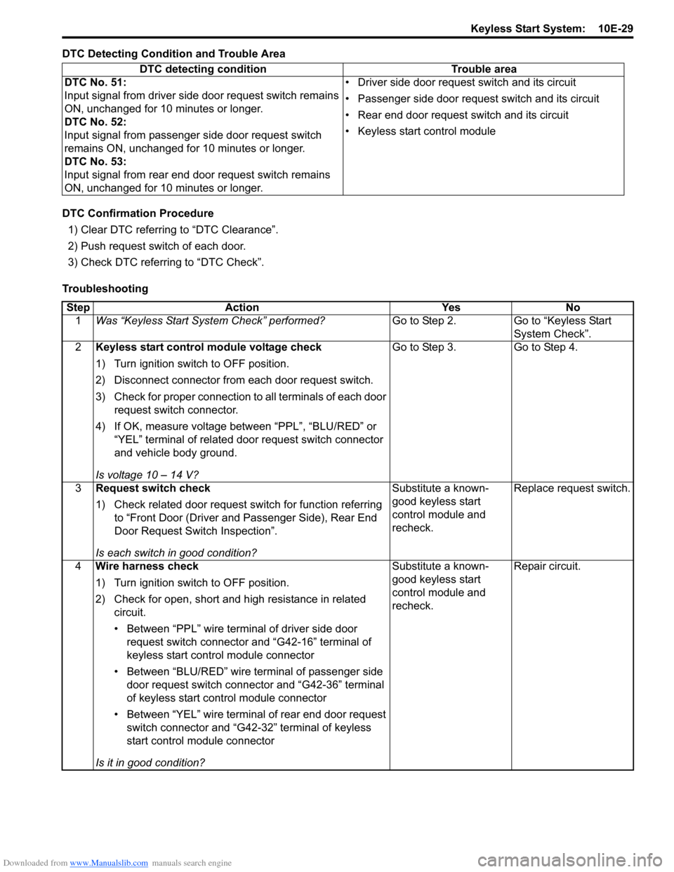
DTC Detecting Condition and Trouble Area
DTC Confirmation Procedure1) Clear DTC referring to “DTC Clearance”.
2) Push request switch of each door.
3) Check DTC referring to “DTC Check”.
Troubleshooting DTC detecting condition Trouble area
DTC No. 51:
Input signal from driver side door request switch remains
ON, unchanged for 10 minutes or longer.
DTC No. 52:
Input signal from passenger side door request switch
remains ON, unchanged for 10 minutes or longer.
DTC No. 53:
Input signal from rear end door request switch remains
ON, unchanged for 10 minutes or longer. • Driver side door request switch and its circuit
• Passenger side door request switch and its circuit
• Rear end door request switch and its circuit
• Keyless start control module
Step
Action YesNo
1 Was “Keyless Start System Check” performed? Go to Step 2.Go to “Keyless Start
System Check”.
2 Keyless start control module voltage check
1) Turn ignition switch to OFF position.
2) Disconnect connector from each door request switch.
3) Check for proper connection to all terminals of each door
request switch connector.
4) If OK, measure voltage between “PPL”, “BLU/RED” or “YEL” terminal of related door request switch connector
and vehicle body ground.
Is voltage 10 – 14 V? Go to Step 3.
Go to Step 4.
3 Request switch check
1) Check related door request switch for function referring
to “Front Door (Driver and Passenger Side), Rear End
Door Request Switch Inspection”.
Is each switch in good condition? Substitute a known-
good keyless start
control module and
recheck.
Replace request switch.
4 Wire harness check
1) Turn ignition switch to OFF position.
2) Check for open, short and high resistance in related
circuit.
• Between “PPL” wire terminal of driver side door request switch connector and “G42-16” terminal of
keyless start control module connector
• Between “BLU/RED” wire terminal of passenger side door request switch connector and “G42-36” terminal
of keyless start control module connector
• Between “YEL” wire terminal of rear end door request switch connector and “G42-32” terminal of keyless
start control module connector
Is it in good condition? Substitute a known-
good keyless start
control module and
recheck.
Repair circuit.
Page 1493 of 1496

Downloaded from www.Manualslib.com manuals search engine Keyless Start System: 10E-31
Front Door (Driver and Passenger Side), Rear
End Door Request Switch Inspection
S7RS0BA506002
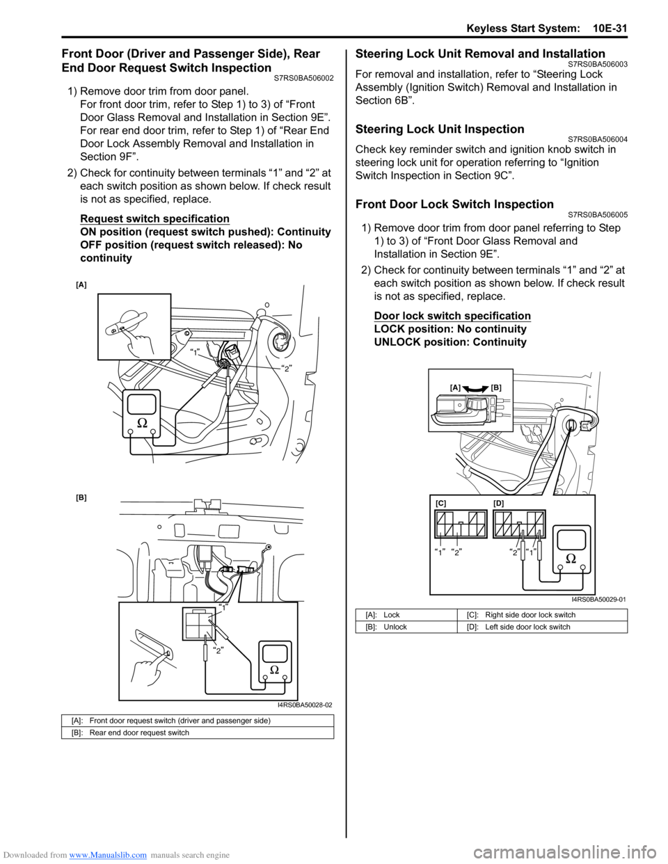
1) Remove door trim from door panel.For front door trim, refer to Step 1) to 3) of “Front
Door Glass Removal and Inst allation in Section 9E”.
For rear end door trim, refer to Step 1) of “Rear End
Door Lock Assembly Remo val and Installation in
Section 9F”.
2) Check for continuity between terminals “1” and “2” at each switch position as shown below. If check result
is not as specified, replace.
Request switch specification
ON position (request switch pushed): Continuity
OFF position (request switch released): No
continuity
Steering Lock Unit Removal and InstallationS7RS0BA506003
For removal and installation, refer to “Steering Lock
Assembly (Ignition Switch) Removal and Installation in
Section 6B”.
Steering Lock Unit InspectionS7RS0BA506004
Check key reminder switch and ignition knob switch in
steering lock unit for operation referring to “Ignition
Switch Inspection in Section 9C”.
Front Door Lock Switch InspectionS7RS0BA506005
1) Remove door trim from door panel referring to Step 1) to 3) of “Front Door Glass Removal and
Installation in Section 9E”.
2) Check for continuity between terminals “1” and “2” at each switch position as sh own below. If check result
is not as specified, replace.
Door lock switch specification
LOCK position: No continuity
UNLOCK position: Continuity
[A]: Front door request switch (driver and passenger side)
[B]: Rear end door request switch
[A]
1
2
[B]
1
2
I4RS0BA50028-02
[A]: Lock [C]: Right side door lock switch
[B]: Unlock [D]: Left side door lock switch
[C][D]
[A] [B]
1212
I4RS0BA50029-01
Page 1494 of 1496

Downloaded from www.Manualslib.com manuals search engine 10E-32 Keyless Start System:
Keyless Start Control Module Removal and
Installation
S7RS0BA506006
Removal1) Disconnect negative (–) cable at battery.
2) Remove glove box from instrument panel.
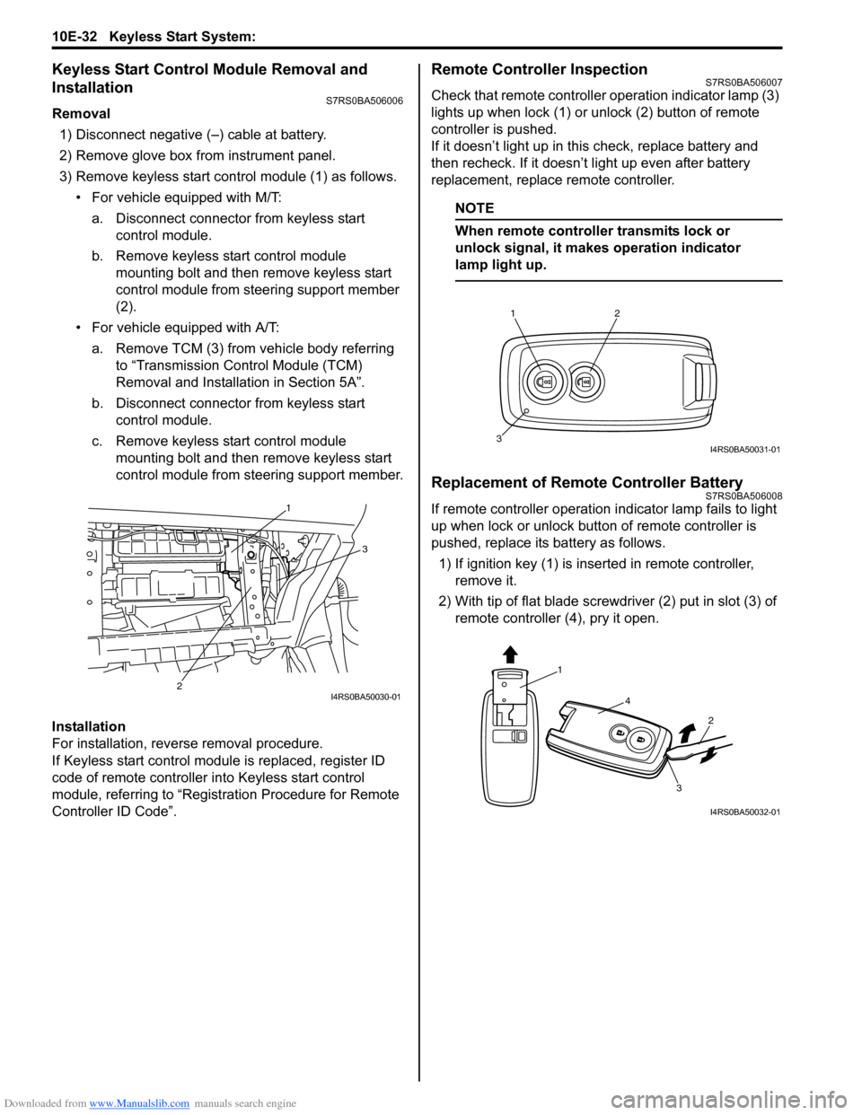
3) Remove keyless start cont rol module (1) as follows.
• For vehicle equipped with M/T:
a. Disconnect connector from keyless start control module.
b. Remove keyless start control module mounting bolt and then remove keyless start
control module from steering support member
(2).
• For vehicle equipped with A/T: a. Remove TCM (3) from vehicle body referring to “Transmission Control Module (TCM)
Removal and Installation in Section 5A”.
b. Disconnect connector from keyless start control module.
c. Remove keyless start control module mounting bolt and then remove keyless start
control module from steering support member.
Installation
For installation, reverse removal procedure.
If Keyless start control module is replaced, register ID
code of remote controller in to Keyless start control
module, referring to “Registration Procedure for Remote
Controller ID Code”.
Remote Controller InspectionS7RS0BA506007
Check that remote controller operation indicator lamp (3)
lights up when lock (1) or un lock (2) button of remote
controller is pushed.
If it doesn’t light up in this check, replace battery and
then recheck. If it doesn’t light up even after battery
replacement, replace remote controller.
NOTE
When remote controller transmits lock or
unlock signal, it makes operation indicator
lamp light up.
Replacement of Remote Controller BatteryS7RS0BA506008
If remote controller operation i ndicator lamp fails to light
up when lock or unlock button of remote controller is
pushed, replace its battery as follows.
1) If ignition key (1) is inse rted in remote controller,
remove it.
2) With tip of flat blade screwdriver (2) put in slot (3) of remote controller (4), pry it open.1
3
2
I4RS0BA50030-01
12
3I4RS0BA50031-01
1
4
2
3
I4RS0BA50032-01