Rear end solenoid SUZUKI SWIFT 2005 2.G Service Workshop Manual
[x] Cancel search | Manufacturer: SUZUKI, Model Year: 2005, Model line: SWIFT, Model: SUZUKI SWIFT 2005 2.GPages: 1496, PDF Size: 34.44 MB
Page 302 of 1496

Downloaded from www.Manualslib.com manuals search engine 1D-17 Engine Mechanical:
Engine Assembly Removal and InstallationS7RS0B1406011
NOTE
After replacing electric throttle body
assembly, perform calibration of throttle
valve referring to “Electric Throttle Body
System Calibration in Section 1C”.
Removal1) Relieve fuel pressure according to “Fuel Pressure Relief Procedure in Section 1G”.
2) Disconnect negative and pos itive cable at battery.
3) Remove battery and tray.
4) Remove engine hood after disconnecting windshield washer hose.
5) Remove right and left side engine under covers.
6) Remove A/C compressor belt by referring to “Compressor Drive Belt Remo val and Installation in
Section 7B” or “Compressor Drive Belt Removal and
Installation in Section 7B”.
7) Drain engine oil, transaxle oil and coolant.
8) Remove cowl top plate referring to “Cowl Top Components in Section 9K”.
9) Remove air cleaner assembly referring to “Air Cleaner Components”.
10) With hose connected, detach A/C compressor from its bracket (A/C model) referring to “Compressor
Assembly Removal and Installation in Section 7B” or
“Compressor Assembly Removal and Installation in
Section 7B”.
CAUTION!
Suspend removed A/C compressor at a place
where no damage will be caused during
removal and installation of engine assembly.
11) Remove intake manifold rear stiffener (1) from intake manifold and cylinder block. 12) Disconnect the following electric wires:
• MAP sensor (1)
• ECT sensor (2)
•EGR valve (3)
• CMP sensor (4)
• Electric throttle body assembly (5)
• Ignition coil assembly (6)
• Injectors (7)
• Heated oxygen sensor No. 2 (8) and No. 1 (9)
• Oil control valve (10)
• Engine oil pressure switch (11)
• CKP sensor (12)
• Knock sensor (13)
• Back up light switch (14)
• Generator (15)
• Starting motor (16)
• Ground terminal (17) from intake manifold
• Battery ground terminal (18) from exhaust manifold
• Battery ground cable (19) from transaxle
• Magnet clutch switch of A/C compressor (A/C model)
• Each wire harness clamps
• Output shaft speed sensor (VSS) (34) (A/T model)
• Solenoid valve (33) (A/T model)
• Transmission range sensor (32) (A/T model)
• Input shaft speed sensor (31) (A/T model)
13) Remove fuse box from its bracket.
14) Disconnect the following cables: • Gear select control cable (23) (M/T model)
• Gear shift control cable (24) (M/T model)
• A/T select cable (A/T model)
15) Disconnect the following hoses: • Brake booster hose (26) from intake manifold
• Radiator inlet and outlet hoses (20) from each pipe
• Heater inlet and outlet hoses (21) from each pipe
• Fuel feed hoses (22) from fuel feed pipe
• EVAP canister purge valve hose (30) from purge pipe
• A/T fluid cooler hoses (A/T model)
16) With hose connected, detach clutch operating cylinder (25). (M/T model)
CAUTION!
Suspend removed clutch operating cylinder
at a place where no damage will be caused
during removal and installation of engine
assembly.
1
I6RS0B141014-01
Page 541 of 1496
Downloaded from www.Manualslib.com manuals search engine ABS: 4E-2
General Description
ABS DescriptionS7RS0B4501001
The ABS (Antilock Brake System) controls the fluid
pressure applied to the wheel cylinder of each brake
from the master cylinder so that each wheel is not locked
even when hard braking is applied.
This ABS has also the following function.
While braking is applied, but before ABS control
becomes effective, braking force is distributed between
the front and rear so as to prevent the rear wheels from
being locked too early for better stability of the vehicle.
The main component parts of this ABS include the
following parts in addition to those of the conventional
brake system.
• Wheel speed sensor which senses revolution speed of each wheel and outputs its signal.
• ABS warning light which light s to inform abnormality
when system fails to operate properly.
• ABS hydraulic unit / cont rol module assembly is
incorporated ABS co ntrol module, ABS hydraulic unit
(actuator assembly), solenoid valve power supply
driver (transistor), solenoid valve driver (transistor),
pump motor driver (transistor).
– ABS control module which sends operation signal to ABS hydraulic unit to control fluid pressure
applied to each wheel cylinder based on signal
from each wheel speed sensor so as to prevent
wheel from locking.
– ABS hydraulic unit which operates according to signal from ABS control module to control fluid
pressure applied to wheel cylinder of each 4
wheels.
– Solenoid valve power supp ly driver (transistor)
which supplies power to solenoid valve in ABS
hydraulic unit.
– Solenoid valve driver (transistor) which controls each solenoid valves in ABS hydraulic unit.
– Pump motor driver (transistor) which supplies power to pump motor in ABS hydraulic unit.
This ABS is equipped with Electronic Brake force
Distribution (EBD) system that controls a fluid pressure
of rear wheels to best condition, which is the same
function as that of proportion ing valve, by the signal from
wheel sensor independently of change of load due to
load capacity and so on. An d if the EBD system fails to
operate properly, the brake warning light lights to inform
abnormality.
ABS Hydraulic Unit / Control Module Assembly
Description
S7RS0B4501002
ABS control module is a component of ABS hydraulic
unit / control module asse mbly and has the following
functions.
Self-Diagnosis Function
ABS control module diagnose s conditions of the system
component parts (whether or not there is any
abnormality) all the time and indicates the results
(warning of abnormality occurrence and DTC) through
the ABS warning light as described.
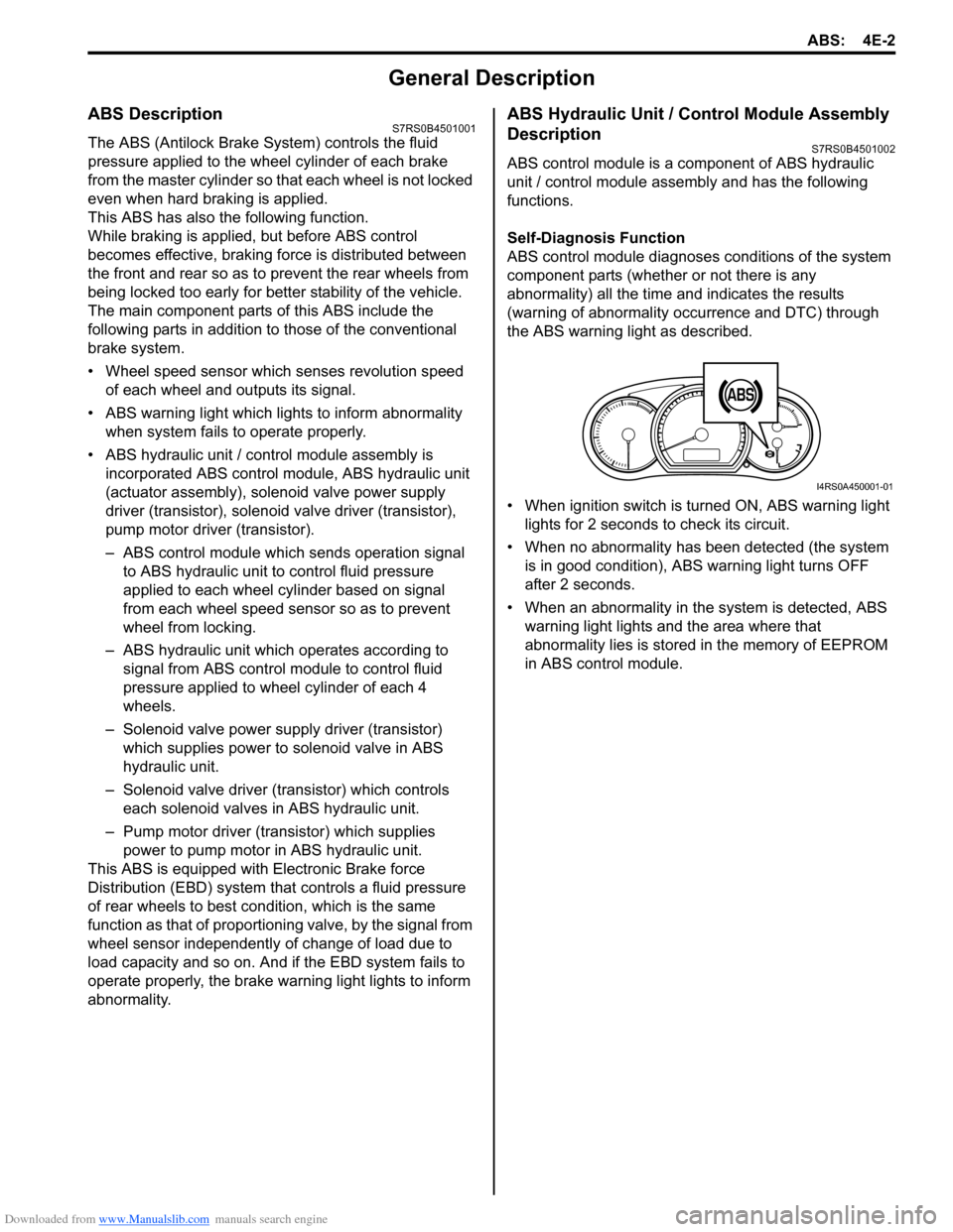
• When ignition switch is turned ON, ABS warning light lights for 2 seconds to check its circuit.
• When no abnormality has been detected (the system is in good condition), ABS warning light turns OFF
after 2 seconds.
• When an abnormality in th e system is detected, ABS
warning light lights and the area where that
abnormality lies is stored in the memory of EEPROM
in ABS control module.
1
I4RS0A450001-01
Page 578 of 1496
Downloaded from www.Manualslib.com manuals search engine 4F-4 Electronic Stability Program:
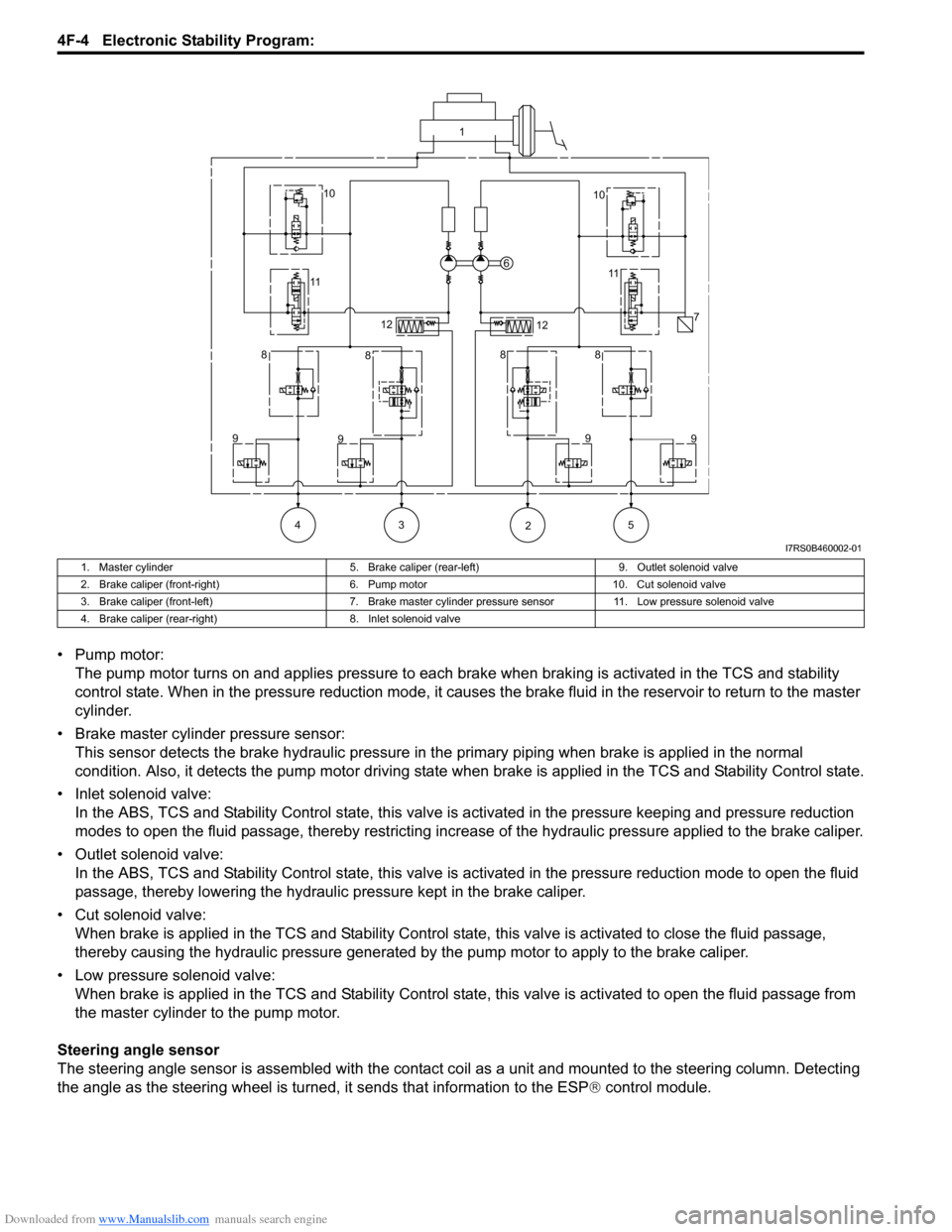
• Pump motor:The pump motor turns on and applies pressure to each brake when braking is activated in the TCS and stability
control state. When in the pressure reduction mode, it causes the brake fluid in the reservoir to return to the master
cylinder.
• Brake master cylinder pressure sensor: This sensor detects the brake hydraulic pressure in th e primary piping when brake is applied in the normal
condition. Also, it detects the pump motor driving state wh en brake is applied in the TCS and Stability Control state.
• Inlet solenoid valve: In the ABS, TCS and Stability Control stat e, this valve is activated in the pressure keeping and pressure reduction
modes to open the fluid passage, thereby restricting increase of the hydraulic pressure applied to the brake caliper.
• Outlet solenoid valve: In the ABS, TCS and Stability Control state, this valve is activated in the pressure reduction mode to open the fluid
passage, thereby lowering the hydraulic pressure kept in the brake caliper.
• Cut solenoid valve: When brake is applied in the TCS and Stability Control state, this valve is activated to close the fluid passage,
thereby causing the hydraulic pressure generated by the pump motor to apply to the brake caliper.
• Low pressure solenoid valve: When brake is applied in the TCS and Stab ility Control state, this valve is activated to open the fluid passage from
the master cylinder to the pump motor.
Steering angle sensor
The steering angle sensor is assembled with the contact co il as a unit and mounted to the steering column. Detecting
the angle as the steering wheel is turned, it sends that information to the ESP ® control module.
1
10 10
11 11
6
7
12 12
8 8 88
9 9 9
9
43 5 2
I7RS0B460002-01
1. Master cylinder 5. Brake caliper (rear-left)9. Outlet solenoid valve
2. Brake caliper (front-right) 6. Pump motor10. Cut solenoid valve
3. Brake caliper (front-left) 7. Brake master cylinder pressure sensor 11. Low pressure solenoid valve
4. Brake caliper (rear-right) 8. Inlet solenoid valve
Page 642 of 1496

Downloaded from www.Manualslib.com manuals search engine 5-ii Table of Contents
DTC P1878: Torque Converter Clutch Shudder .......................................................... 5A-75
DTC P2762: Torque Converter Clutch (TCC) Pressure Control Sole noid Control Circuit
Range /Performance ....................................... 5A-76
DTC P2763: Torque Converter Clutch Pressure Control Sole noid Control Circuit
High ................................................................. 5A-78
DTC P2764: Torque Converter Clutch Circuit Pressure Control Sole noid Control Circuit
Low ................................................................. 5A-80
Inspection of TCM and Its Circuits .................... 5A-82
TCM Power and Ground Circuit Check ............. 5A-86
Brake Interlock System Inspection .................... 5A-87
Repair Instructions ........... .................................5A-88
Learning Control Initializat ion ............................ 5A-88
A/T Fluid Level Check ....................................... 5A-89
A/T Fluid Change .............................................. 5A-90
Select Lever Components ... .............................. 5A-90
Select Lever Assembly Removal and Installation ....................................................... 5A-90
Select Lever Knob Installa tion........................... 5A-90
Select Lever Inspection .... ................................. 5A-91
“3” Position Switch Inspec tion ........................... 5A-91
Shift Lock Solenoid Inspec tion .......................... 5A-91
Shift Lock Solenoid Replacement ..................... 5A-91
Select Cable Components ................................ 5A-92
Select Cable Removal and Installation ............. 5A-92
Select Cable Adjustment ................................... 5A-93
Key Interlock Cable Removal and Installation... 5A-93
Transmission Range Sensor (Shift Switch) Inspection and Adjustment .............................. 5A-95
Output Shaft Speed Sensor Removal and Installation ....................................................... 5A-96
Output Shaft Speed Sensor Inspection ............. 5A-96
Input Shaft Speed Sensor Removal and Installation ....................................................... 5A-96
Input Shaft Speed Sensor Inspection................ 5A-97
Transmission Fluid Temperature Sensor Removal and Installation ................................. 5A-97
Transmission Fluid Temperature Sensor Inspection ........................................................ 5A-98
Solenoid Valves (Shift Solenoid Valves and Timing Solenoid Valve) Removal and
Installation ....................................................... 5A-98
Solenoid Valves (Shift Solenoid Valves, and Timing Solenoid Valve) Inspection .................. 5A-99
Pressure Control Soleno id Valves (Pressure
Control Solenoid and TCC Pressure Control
Solenoid) Removal and Inst allation .............. 5A-101
Pressure Control Solenoid Valve Inspection ... 5A-101
Transmission Control Module (TCM) Removal and Installation ............................... 5A-102
A/T Relay Inspection ....................................... 5A-103
Differential Side Oil Seal Replacement ........... 5A-103
A/T Fluid Cooler Hoses Replacement ............. 5A-104
Automatic Transaxle Unit Components........... 5A-105
Automatic Transaxle Unit Dismounting and Remounting ................................................... 5A-106
Automatic Transaxle Asse mbly Components . 5A-108 Automatic Transaxle Unit
Disassembly........... 5A-110
Oil Pump Assembly Components ................... 5A-121
Oil Pump Assembly Disassembly and Reassembly .................................................. 5A-122
Oil Pump Assembly Inspection ....................... 5A-122
Direct Clutch Assembly Components.............. 5A-124
Direct Clutch Assembly Preliminary Check ..... 5A-124
Direct Clutch Assembly Disassembly and Reassembly .................................................. 5A-125
Direct Clutch Assembly Inspection.................. 5A-127
Forward and Reverse Clutch Assembly Components .................................................. 5A-128
Forward and Reverse Clutch Assembly Preliminary Check ......................................... 5A-129
Forward and Reverse Clutch Assembly Disassembly and Reassembly ...................... 5A-129
Forward and Reverse Clutch Assembly Inspection ...................................................... 5A-133
2nd Brake Piston Assembly Components ....... 5A-134
2nd Brake Piston Assembly Disassembly and Reassembly .................................................. 5A-134
Transaxle Rear Cover (O/D and 2nd Coast Brake Piston) Assembly Components........... 5A-135
Transaxle Rear Cover (O/D and 2nd Coast Brake Piston) Assembly Disassembly and
Reassembly .................................................. 5A-136
Transaxle Rear Cover (O/D and 2nd Coast Brake Piston) Assembly Inspection............... 5A-137
Countershaft Assembly Co mponents.............. 5A-138
Countershaft Assembly Disassembly and Reassembly .................................................. 5A-138
Valve Body Assembly Components ................ 5A-139
Valve Body Assembly Disassembly and Reassembly .................................................. 5A-140
Differential Assembly Components ................. 5A-141
Differential Assembly Disassembly and Reassembly .................................................. 5A-142
Differential Assembly Inspection ..................... 5A-143
Torque Converter Housing Disassembly and Reassembly .................................................. 5A-144
Transaxle Case Disassembly and Reassembly .................................................. 5A-146
Automatic Transaxle Unit Inspection and Adjus
tment .................................................... 5A-147
Automatic Transaxle Unit Assembly ............... 5A-150
Specifications .................. .................................5A-167
Tightening Torque Specifications .................... 5A-167
Special Tools and Equipmen t .........................5A-168
Recommended Service Material ..................... 5A-168
Special Tool .................................................... 5A-168
Manual Transmission/Tr ansaxle ............ 5B-1
General Description .............................................5B-1
Manual Transaxle Construction and Servicing .... 5B-1
Diagnostic Information and Procedures ............5B-3 Manual Transaxle Symptom Diagnosis............... 5B-3
Repair Instructions ............ ..................................5B-3
Manual Transaxle Oil Change............................. 5B-3
Differential Side Oil Seal Replacement ............... 5B-4
Page 1200 of 1496
Downloaded from www.Manualslib.com manuals search engine 9A-29 Wiring Systems:
RearS7RS0B910A006
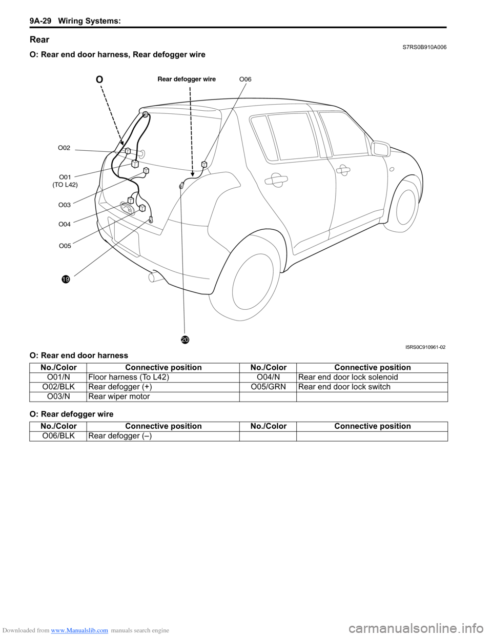
O: Rear end door harness, Rear defogger wire
O: Rear end door harness
O: Rear defogger wire
ORear defogger wire
O01
(TO L42) O02
O03
19
O04
O05
O06
20I5RS0C910961-02
No./Color Connective position No./ColorConnective position
O01/N Floor harness (To L42) O04/N Rear end door lock solenoid
O02/BLK Rear defogger (+) O05/GRN Rear end door lock switch
O03/N Rear wiper motor
No./Color Connective position No./ColorConnective position
O06/BLK Rear defogger (–)
Page 1231 of 1496
Downloaded from www.Manualslib.com manuals search engine Wiring Systems: 9A-60
1817
GRN/WHTBRN
"E-1"
"E-2"
HVAC
control unit
Auto
unit
G37
Flasher relay Relay
Relay
H
12
"Junction Block
Inner circuit"
J/B (BCM- 12 )J/B (BCM- 18 )
1618
J/B (BCM- 16 )
J/B
"B-5""B-5""B-5""B-5"
11
9
L06
22
10
21
Rear
J/B
GRN
GRN
RED/BLU
RED/BLURED/BLU
RED/BLUGRNRED/BLU
GRN
110
GRN/REDRED/BLURED/BLUBLU/YEL
Rear end
L014
WHT
Rear end
door lock switch
3
"D-5"
BLK/YEL
L01
Luggage compartment light
7
6K01
Interior light
"D-5"
WHT/RED
WR
J/B side connector (BCM)
A
A
A
BY
GWB
W
BYGRRBGGRBGRBGRB
"B-5"
SolenoidMotor (R)
"B-5"
Rear
Motor (L)
"B-3"
HVAC
control unit
BCM
BLK/YEL
BY
BLK/YEL
"D-5"
Solenoid
Rear end
A
A
A
J/C
L74
I7RS0B910918-01
Page 1239 of 1496
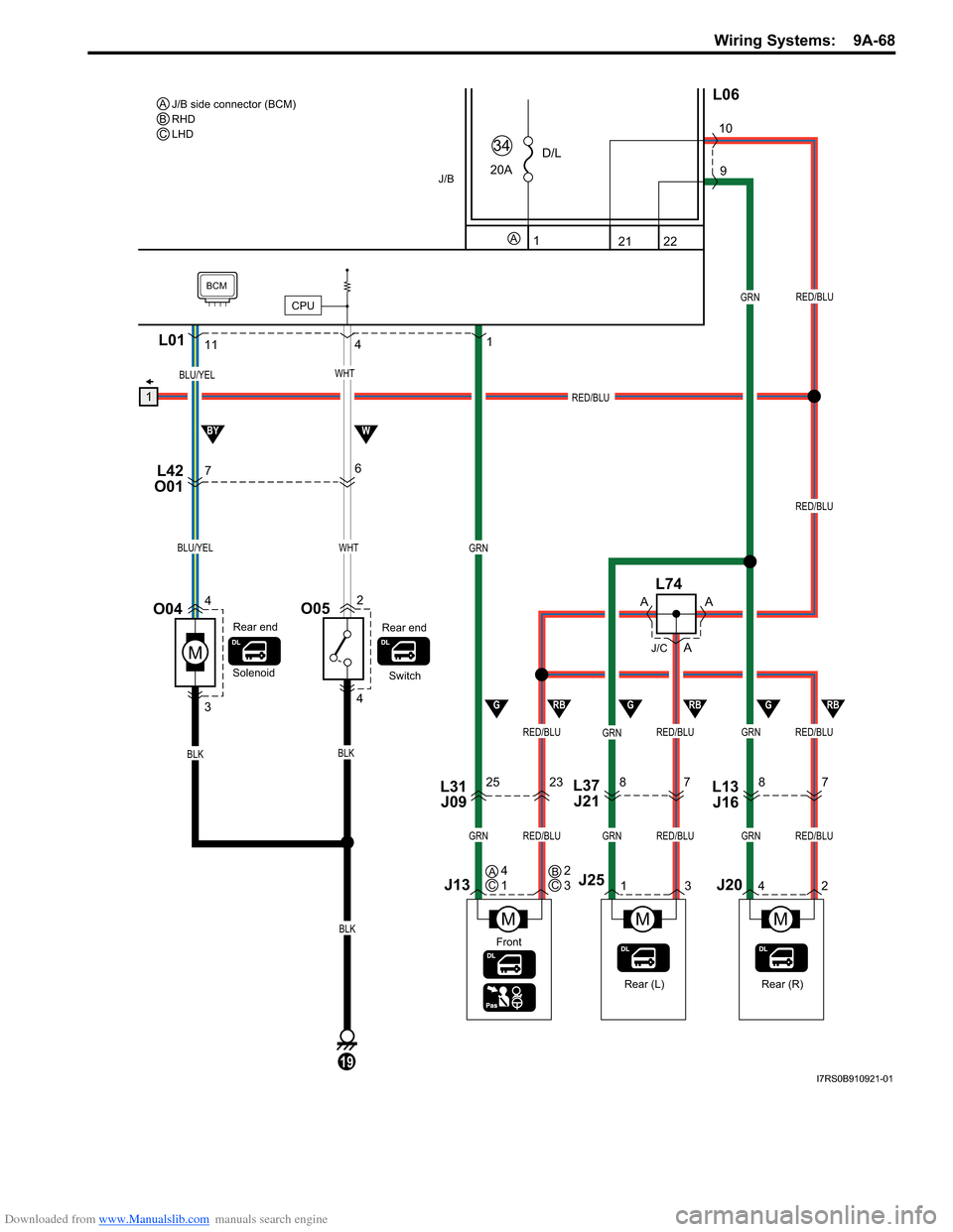
Downloaded from www.Manualslib.com manuals search engine Wiring Systems: 9A-68
114
10
L06
21 9
221
8
42L13 J1678L37J217
7L42
O01
O04
Rear (R)
J/B
GRN
GRN
RED/BLU
J20
RED/BLUGRNRED/BLU
GRN
RED/BLU
D/L
20A34
3
M
1
J13
L01
M
13
Rear (L)
J25
M
25L31 J0923
M
GRNRED/BLUGRNRED/BLUGRNRED/BLU
BLU/YEL
BLU/YEL
BCM
1
Switch
6
4
O05
BLK
19
WHT
WHT
BLKBLK
RED/BLU
RED/BLU
CPU
2
4
Solenoid
A
Rear end
BY
GRBGRBGRB
Rear end
W
Front
J/B side connector (BCM)
RHD
LHD
A
BC
C
A4
1CB2
3
A
A
A
J/C
L74
I7RS0B910921-01
Page 1253 of 1496
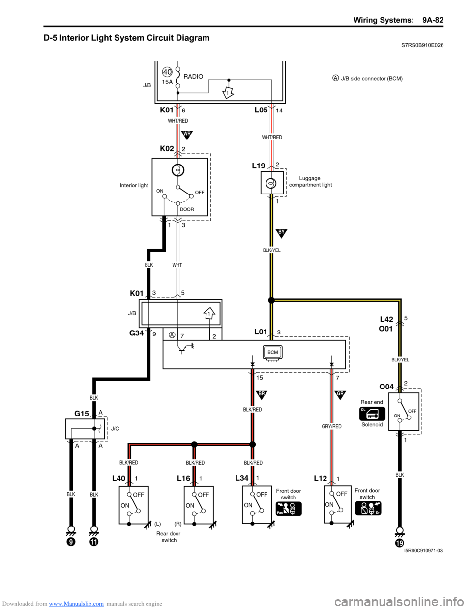
Downloaded from www.Manualslib.com manuals search engine Wiring Systems: 9A-82
D-5 Interior Light System Circuit DiagramS7RS0B910E026
15A
40RADIO
J/B
OFF
DOOR
ON
K02 K012 6
3
1
Interior light
15
7
OFF
ON
OFF
ON
L121
1
GRY/RED
BLK
OFF
ONOFF
ON
L16 L341L401
Rear door
switch Front door
switch
BLK/RED
BLK
BLK
BLK
L0514
WHT/RED
G15
J/C
A
A
5
7G34
K01
J/B
L01
Luggage
compartment light
2
1
3L19
WHT/RED
BLK/YEL
WHT
1119
OFF
ON
O042
L42
O015
1
BLK/YEL
3
Solenoid
2
1
1
J/B side connector (BCM)
A
(L) (R) Front door
switch
A
BLK/REDBLK/REDBLK/RED
Rear end
9
BRGR
9
BLK
A
BY
WR
BCM
I5RS0C910971-03
Page 1469 of 1496
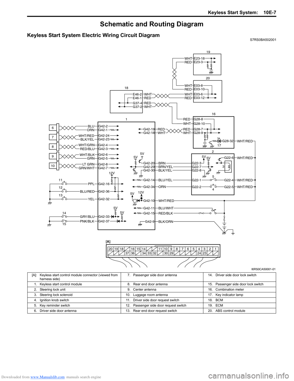
Downloaded from www.Manualslib.com manuals search engine Keyless Start System: 10E-7
Schematic and Routing Diagram
Keyless Start System Electric Wiring Circuit DiagramS7RS0BA502001
BLK/ORNG42-9
G42-15
G42-14
G42-37G42-33
G42-16
G42-20G42-29G42-30
G42-36
G42-32G42-10
G42-34
G42-11BLU/WHT
WHT/RED
WHT/RED
WHT/RED
PNK/BLKGRY/BLU
BLU/RED
YEL
PPL
RED/BLK
5V5V
5V5V
5V5V
5V
12V
12V
G42-2G42-1BLUORNWHTREDWHTREDG42-18G42-19G28-9G28-7
BLU/YEL
ORN
G42-24G42-23BLK/YELWHT/RED
G42-7GRN/WHTLT G R NG42-8
G42-5G42-6GRNWHT/BLK
G42-4G42-3WHT/GRNRED/BLU
BLK/YELBRN/YELBRNG22-3
G22-1
G22-2G22-5
G22-4
G22-6
G22-7G22-8
WHT/RED
WHT/RED
G37-4
REDWHTREDWHT
G28-10G28-8WHTRED
RED
WHT
G37-2
E46-2
E46-1E03-6
E03-12
G28-32
6
7
8
9
10
11
12
13
14
15 1
18
20
1617
2
4 5 3
1234567891011
141516
36 34 33 32 30 29 24 23
37
181920
[A]
REDWHTE23-18
E23-3
19
REDWHTE03-8
E03-10
I6RS0CA50001-01
[A]: Keyless start control module connector (viewed from
harness side) 7. Passenger side door antenna 14. Driver side door lock switch
1. Keyless start control module 8. Rear end door antenna 15. Passenger side door lock switch
2. Steering lock unit 9. Center antenna 16. Combination meter
3. Steering lock solenoid 10. Luggage room antenna 17. Key indicator lamp
4. Ignition knob switch 11. Driver side door request switch 18. BCM
5. Key reminder switch 12. Passenger side door request switch 19. ECM
6. Driver side door antenna 13. Rear end door request switch 20. ABS control module