Steering wheel wire SUZUKI SWIFT 2005 2.G Service Workshop Manual
[x] Cancel search | Manufacturer: SUZUKI, Model Year: 2005, Model line: SWIFT, Model: SUZUKI SWIFT 2005 2.GPages: 1496, PDF Size: 34.44 MB
Page 6 of 1496
Downloaded from www.Manualslib.com manuals search engine 00-1 Precautions:
Precautions
Precautions
Precautions
Precautions for Vehicles Equipped with a
Supplemental Restraint (Air Bag) System
S7RS0B0000001
WARNING!
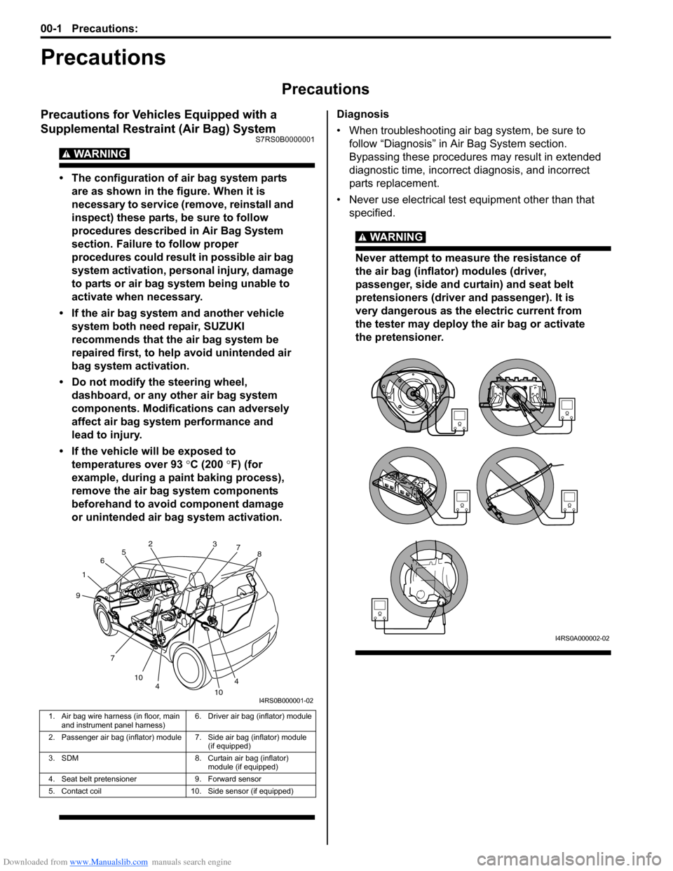
• The configuration of air bag system parts are as shown in the figure. When it is
necessary to service (remove, reinstall and
inspect) these parts, be sure to follow
procedures described in Air Bag System
section. Failure to follow proper
procedures could result in possible air bag
system activation, personal injury, damage
to parts or air bag system being unable to
activate when necessary.
• If the air bag system and another vehicle system both need repair, SUZUKI
recommends that the air bag system be
repaired first, to help avoid unintended air
bag system activation.
• Do not modify the steering wheel, dashboard, or any other air bag system
components. Modifications can adversely
affect air bag system performance and
lead to injury.
• If the vehicle will be exposed to temperatures over 93 °C (200 °F) (for
example, during a paint baking process),
remove the air bag system components
beforehand to avoid component damage
or unintended air bag system activation.
Diagnosis
• When troubleshooting air bag system, be sure to follow “Diagnosis” in Air Bag System section.
Bypassing these procedures may result in extended
diagnostic time, incorrect diagnosis, and incorrect
parts replacement.
• Never use electrical test equipment other than that specified.
WARNING!
Never attempt to measure the resistance of
the air bag (inflator) modules (driver,
passenger, side and curtain) and seat belt
pretensioners (driver and passenger). It is
very dangerous as the electric current from
the tester may deploy the air bag or activate
the pretensioner.
1. Air bag wire harness (in floor, main and instrument panel harness) 6. Driver air bag (inflator) module
2. Passenger air bag (inflator) module 7. Side air bag (inflator) module (if equipped)
3. SDM 8. Curtain air bag (inflator) module (if equipped)
4. Seat belt pretensioner 9. Forward sensor
5. Contact coil 10. Side sensor (if equipped)
1 2
3
4
4
5
6
7 7
8
9
10 10
I4RS0B000001-02
I4RS0A000002-02
Page 16 of 1496
Downloaded from www.Manualslib.com manuals search engine 00-11 Precautions:
Precaution for Vehicle Equipped with ESP®
System
S7RS0B0000015
• When testing with any of the following equipments
(when vehicle is tested by rotating wheels (tires)
under vehicle stop), be sure to deactivate ESP ®
system referring to “Precautions in Speedometer Test
or Other Tests in Section 4F” to obtain correct data.
– 2 or 4-wheel chassis dynamometer
– Speedometer tester
– Brake tester
–Etc.
ESP ® control module
• When ESP ® control module is removed / installed, do
not use impact wrenches which generate shock or
impact to avoid damaging sensors in ESP ® control
module.
• When any of the following operation is done, calibrate steering angle sensor referring to “Sensor Calibration
in Section 4F”.
– When battery or dome fuse is removed.
– When steering angle sensor is replaced.
Brake CautionS7RS0B0000014
CAUTION!
All brake fasteners are important attaching
parts in that they could affect the
performance of vital parts and systems, and/
or could result in major repair expense. They
must be replaced with one of same part
number or with an eq uivalent part if
replacement becomes necessary. Do not use
a replacement part of lesser quality or
substitute design. Torque values must be
used as specified during reassembly to
assure proper retention of all parts. There is
to be no welding as it may result in extensive
damage and weakening of the metal.
Repair Instructions
Electrical Circuit Inspection ProcedureS7RS0B0006001
While there are various electrical circuit inspection
methods, described here is a general method to check
its open and short circuit by using an ohmmeter and a
voltmeter.
Open Circuit Check
Possible causes for the open circuit are as follows. As
the cause is in the connector or terminal in many cases,
they need to be checked particularly carefully.
• Loose connection of connector
• Poor contact of terminal (due to dirt, corrosion or rust
on it, poor contact tension, entry of foreign object etc.)
• Wire harness being open
When checking system circuits including an electronic
control unit such as ECM, TCM, ABS control module,
etc., it is important to perfor m careful check, starting with
items which are easier to check.
1) Disconnect negative (–) cable from battery
2) Check each connector at both ends of the circuit being checked for loose connection. Also check lock
condition of connector if equipped with connector
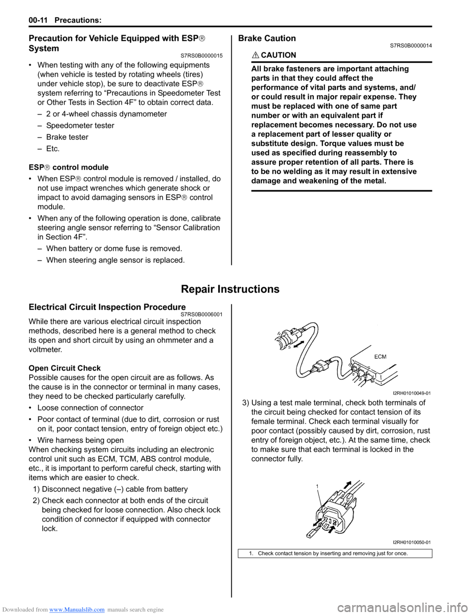
lock. 3) Using a test male terminal
, check both terminals of
the circuit being checked for contact tension of its
female terminal. Check each terminal visually for
poor contact (possibly caused by dirt, corrosion, rust
entry of foreign object, etc.). At the same time, check
to make sure that each te rminal is locked in the
connector fully.
1. Check contact tension by inserting and removing just for once.
I2RH01010049-01
I2RH01010050-01
Page 21 of 1496
Downloaded from www.Manualslib.com manuals search engine Table of Contents 0- i
0
Section 0
CONTENTS
General Information
General Information ................................ 0A-1
General Description ............................................. 0A-1
Abbreviations ...................................................... 0A-1
Symbols .............................................................. 0A-2
Wire Color Symbols ............................................ 0A-2
Fasteners Information ......................................... 0A-3
Vehicle Lifting Points ........................................... 0A-5
Engine Supporting Points ................................... 0A-7
Vehicle Identification Number ............................. 0A-7
Engine Identification Number .............................. 0A-7
Transmission Identification Number .................... 0A-7
Component Locatio n ........................................... 0A-8
Warning, Caution and Information Labels Location ............................................................ 0A-8
Maintenance and Lubricat ion ................. 0B-1
Precautions........................................................... 0B-1
Precautions for Maintenance and Lubrication ..... 0B-1
Scheduled Maintenance ...................................... 0B-1 Maintenance Schedule under Normal Driving Conditions ......................................................... 0B-1
Maintenance Recommended under Severe Driving Conditions ............................................. 0B-2
Repair Instructions .............................................. 0B-3 Accessory Drive Belt Inspection.......................... 0B-3
Accessory Drive Belt Repl acement ..................... 0B-4
Valve Lash (Clearance) Inspection ..................... 0B-4
Engine Oil and Filter Change .............................. 0B-4
Engine Coolant Change ...... ................................ 0B-5
Exhaust System Inspection ................................. 0B-6
Spark Plug Replacement .................................... 0B-6
Air Cleaner Filter Inspection ................................ 0B-6
Air Cleaner Filter Replac ement ........................... 0B-6 Fuel Lines and Connections Inspection .............. 0B-6
Fuel Filter Replacement ...................................... 0B-7
Fuel Tank Inspection ........................................... 0B-7
PCV Valve Inspection ......................................... 0B-7
Fuel Evaporative Emission Control System
Inspection .......................................................... 0B-7
Brake Discs and Pads Inspection ....................... 0B-7
Brake Hoses and Pipes Inspection ..................... 0B-7
Brake Fluid Inspection......................................... 0B-8
Brake Fluid Replacement .................................... 0B-8
Brake Lever and Cable Inspection ...................... 0B-8
Clutch Fluid Inspection ........................................ 0B-8
Tires Inspection ................................................... 0B-9
Wheel Discs Inspection ....................................... 0B-9
Wheel Bearing Inspection ................................... 0B-9
Suspension System Inspection ........................... 0B-9
Steering System Inspection .............................. 0B-10
Drive Shaft (Axle) Boots Inspection .................. 0B-10
Manual Transaxle Oil Inspection ....................... 0B-10
Manual Transaxle Oil Replacement .................. 0B-10
Automatic Transaxle Fluid Level Inspection...... 0B-11
Automatic Transaxle Fluid Replacement .......... 0B-11
Automatic Transaxle Fluid Cooler Hose Inspection ........................................................ 0B-11
All Latches, Hinges and Locks Inspection......... 0B-11
HVAC Air Filter (If Equipped) Inspection ........... 0B-12
HVAC Air Filter (If Equipped) Replacement ...... 0B-12
Final Inspection for Maint enance Service ......... 0B-12
Specifications .................... .................................0B-13
Tightening Torque Specifications ...................... 0B-13
Special Tools and Equipmen t ...........................0B-13
Recommended Fluids and Lubricants............... 0B-13
Special Tool ...................................................... 0B-14
Page 23 of 1496
Downloaded from www.Manualslib.com manuals search engine General Information: 0A-2
SAS: Steering Angle Sensor
SDM: Sensing and Diagnostic Module (Air Bag Controller, Air bag Control Module)
SDT: Smart Diagnostic Tester
SFI: Sequential Multipor t Fuel Injection
SOHC: Single Over Head Camshaft
T:
TBI: Throttle Body Fuel Injection (Single-Point Fuel
Injection, SPI)
TCC: Torque Converter Clutch
TCM: Transmission Control Module (A/T Controller, A/T
Control Module)
TDC: Top Dead Center
TP Sensor: Throttle Position Sensor TVV:
Thermal Vacuum Valve (Thermal Vacuum
Switching Valve, TVSV, Bi metal Vacuum Switching
Valve, BVSV)
TWC: Three Way Catalytic Converter (Three Way
Catalyst)
2WD: 2 Wheel Drive
U:
USB: Universal Serial Bus
V:
VIN: Vehicle Identification Number
VSS: Vehicle Speed Sensor
VVT: Variable Valve Timing (Camshaft Position Control)
W:
WU-OC: Warm Up Oxidation Catalytic Converter
WU-TWC: Warm Up Three Way Catalytic Converter
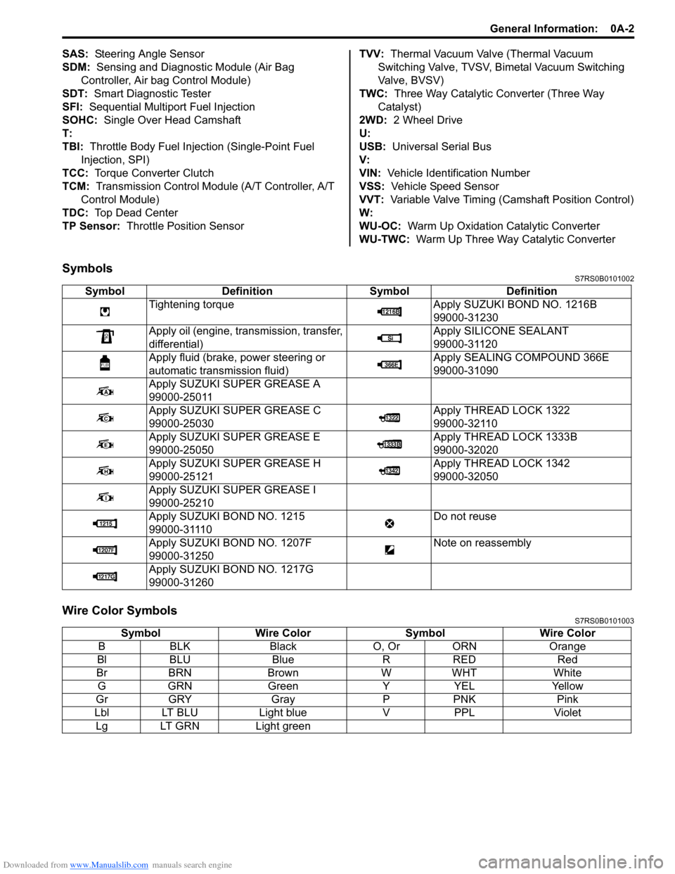
SymbolsS7RS0B0101002
Wire Color SymbolsS7RS0B0101003
Symbol Definition SymbolDefinition
Tightening torque Apply SUZUKI BOND NO. 1216B
99000-31230
Apply oil (engine, transmission, transfer,
differential) Apply SILICONE SEALANT
99000-31120
Apply fluid (brake, power steering or
automatic transmission fluid) Apply SEALING COMPOUND 366E
99000-31090
Apply SUZUKI SUPER GREASE A
99000-25011
Apply SUZUKI SUPER GREASE C
99000-25030 Apply THREAD LOCK 1322
99000-32110
Apply SUZUKI SUPER GREASE E
99000-25050 Apply THREAD LOCK 1333B
99000-32020
Apply SUZUKI SUPER GREASE H
99000-25121 Apply THREAD LOCK 1342
99000-32050
Apply SUZUKI SUPER GREASE I
99000-25210
Apply SUZUKI BOND NO. 1215
99000-31110 Do not reuse
Apply SUZUKI BO ND NO. 1207F
99000-31250 Note on reassembly
Apply SUZUKI BO ND NO. 1217G
99000-31260
Symbol Wire Color SymbolWire Color
B BLK Black O, Or ORN Orange
Bl BLU Blue RRED Red
Br BRN Brown WWHT White
G GRN Green YYEL Yellow
Gr GRY Gray PPNK Pink
Lbl LT BLU Light blueVPPL Violet
Lg LT GRN Light green
Page 232 of 1496
Downloaded from www.Manualslib.com manuals search engine 1A-182 Engine General Information and Diagnosis:
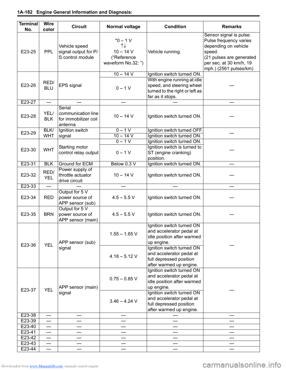
E23-25 PPLVehicle speed
signal output for P/
S control module *0 – 1 V
↑↓
10 – 14 V
(“Reference
waveform No.32: ”) Vehicle running. Sensor signal is pulse.
Pulse frequency varies
depending on vehicle
speed.
(21 pulses are generated
per sec. at 30 km/h, 19
mph.) (2561 pulses/km)
E23-26 RED/
BLU EPS signal 10 – 14 V Ignition switch turned ON.
—
0 – 1 V With engine running at idle
speed, and steering wheel
turned to the right or left as
far as it stops.
E23-27 — — — — —
E23-28 YEL/
BLK Serial
communication line
for immobilizer coil
antenna
10 – 14 V Ignition switch turned ON. —
E23-29 BLK/
WHT Ignition switch
signal 0 – 1 V Ignition switch turned OFF.
—
10 – 14 V Ignition switch turned ON.
E23-30 WHT Starting motor
control relay output 0 – 1 V Ignition switch turned ON.
—
0 – 1 V Ignition switch is turned to
ST (engine cranking)
position.
E23-31 BLK Ground for ECM Below 0.3 V Ignition switch turned ON. —
E23-32 RED/
YEL Power supply of
throttle actuator
drive circuit
10 – 14 V Ignition switch turned ON. —
E23-33 — — — — —
E23-34 RED Output for 5 V
power source of
APP sensor (sub) 4.5 – 5.5 V Ignition switch turned ON. —
E23-35 BRN Output for 5 V
power source of
APP sensor (main) 4.5 – 5.5 V Ignition switch turned ON. —
E23-36 YEL APP sensor (sub)
signal 1.55 – 1.65 V
Ignition switch turned ON
and accelerator pedal at
idle position after warmed
up engine.
—
4.18 – 5.12 V Ignition switch turned ON
and accelerator pedal at
full depressed position
after warmed up engine.
E23-37 YEL APP sensor (main)
signal 0.75 – 0.85 V
Ignition switch turned ON
and accelerator pedal at
idle position after warmed
up engine.
—
3.46 – 4.24 V Ignition switch turned ON
and accelerator pedal at
full depressed position
after warmed up engine.
E23-38 — — — — —
E23-39 — — — — —
E23-40 — — — — —
E23-41 — — — — —
E23-42 — — — — —
E23-43 — — — — —
E23-44 — — — — —
Terminal
No. Wire
color Circuit Normal voltage Condition Remarks
Page 595 of 1496
Downloaded from www.Manualslib.com manuals search engine Electronic Stability Program: 4F-21
Stability control (ACTIVE, INACTIVE): This indicates
stability control in acti vation / deactivation.
TCS control (brake) ( ACTIVE, INACTIVE): This
indicates brake function of TCS in activation /
deactivation.
TCS control (engine) (ACTIVE, INACTIVE): This
indicates torque control of TCS in activation /
deactivation. ESP®
off state (cont) (ESP ® ON, ESP ® OFF): State
of ESP ® OFF switch.
Steering angle Sen (Neutral, NON newtral): This
indicates steering wheel angle measured by steering
angle sensor is in straight-ahead or not.
Visual InspectionS7RS0B4604059
Check the following parts and systems visually.
ESP ® Warning Lamp Does Not Come ON at Ignition Switch ONS7RS0B4604008
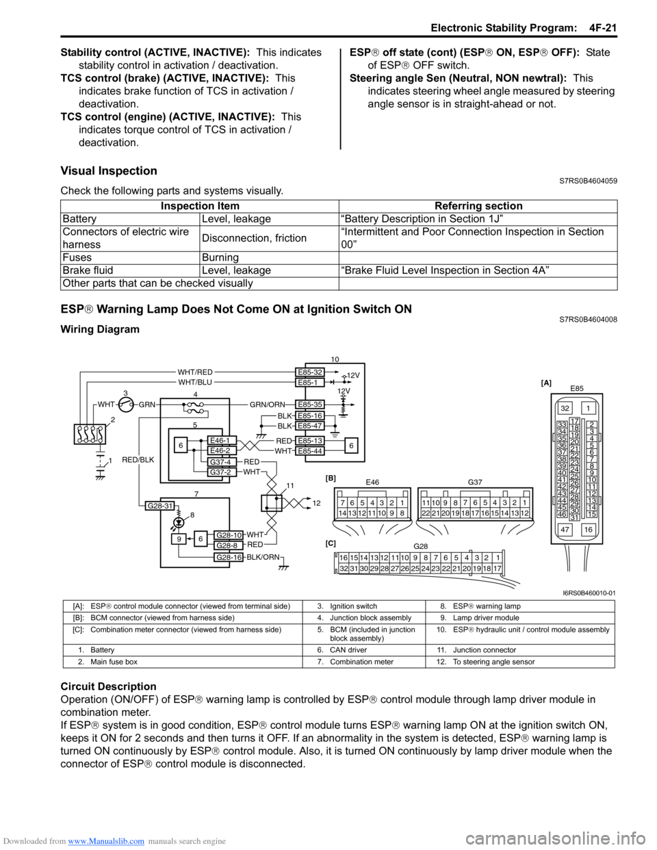
Wiring Diagram
Circuit Description
Operation (ON/OFF) of ESP ® warning lamp is controlled by ESP ® control module through lamp driver module in
combination meter.
If ESP ® system is in good condition, ESP ® control module turns ESP ® warning lamp ON at the ignition switch ON,
keeps it ON for 2 seconds and then turns it OFF. If an abnormality in the system is detected, ESP ® warning lamp is
turned ON continuously by ESP ® control module. Also, it is turned ON continuously by lamp driver module when the
connector of ESP ® control module is disconnected.Inspection Item Referring section
Battery Level, leakage “Battery Description in Section 1J”
Connectors of electric wire
harness Disconnection, friction“Intermittent and Poor Connec
tion Inspection in Section
00”
Fuses Burning
Brake fluid Level, leakage “Brake Fluid Level Inspection in Section 4A”
Other parts that can be checked visually
[A] E85
161
15
2
3
4
5
6
7
8
9
10
11
12
13
14
17
18
19
20
21
22
23
24
25
26
27
28
29
30
31
3233
34
35
36
37
38
39
40
41
42
43
44
45
46
47
WHTGRN
3
E85-13
E85-44REDWHT6 5E46-1E46-2
4 10
6
E85-16
E85-47BLKBLK
8
9
BLK/ORN
REDWHT
REDWHT
G37-4G37-2
G28-10G28-8
G28-16
12V
12VE85-32E85-1
E85-35
WHT/REDWHT/BLU
GRN/ORN
6
2
1
7 1112[B]
G37
E46124
53
67
891011121314124
53
67
891011
1213141516171819202122
[C] G28
12345678910111213141516
17181920212223242526272829303132
G28-31
RED/BLK
I6RS0B460010-01
[A]: ESP ® control module connector (viewed from terminal side) 3. Ignition switch 8. ESP ® warning lamp
[B]: BCM connector (viewed from harness side) 4. Junction block assembly 9. Lamp driver module
[C]: Combination meter connector (viewed from harness side) 5. BCM (included in junction
block assembly) 10. ESP
® hydraulic unit / control module assembly
1. Battery 6. CAN driver 11. Junction connector
2. Main fuse box 7. Combination meter 12. To steering angle sensor
Page 890 of 1496
Downloaded from www.Manualslib.com manuals search engine 6C-8 Power Assisted Steering System:
Step 2: DTC Check, Record and Clearance
First, check DTC, referring to “DTC Check”. If DTC is
indicated, print it or write them down and then clear them
by referring to “DTC Clearance”. DTC indicates
malfunction that occurred in the system but does not
indicate whether it exists now or it occurred in the past
and the normal condition has been restored now. To
check which case applies, check the symptom in
question according to Step 5 and recheck DTC
according to Step 6 and 7.
Attempt to diagnose a trouble based on DTC in this step
only or failure to clear the DTC in this step will lead to
incorrect diagnosis, trouble diagnosis of a normal circuit
or difficulty in troubleshooting.
Step 3 and 4: Visual Inspection
As a preliminary step, be sure to perform visual check of
the items that support proper function of the P/S system
referring to “Visual Inspection”.
Step 5: Trouble Symptom Confirmation
Based on information obtained in “Step 1: Customer
Complaint Analysis: ” and “S tep 2: DTC Check, Record
and Clearance: ”, confirm trouble symptoms. Also,
reconfirm trouble symptom by performing test drive and
turning steering wheel fully to right and left at stopped
vehicle.
Step 6 and 7: Rechecking and Record of DTC
Refer to “DTC Check” for checking procedure.
Step 8: Steering Symptom Diagnosis and P/S
System Symptom Diagnosis
Perform basic steering system check according to
“Steering Symptom Diagnosis in Section 6A” first. When
the end of the flow has been reached, check the parts of
the system suspected as a possible cause referring to
“P/S System Symptom Diagnosis” and based on
symptoms appearing on the vehicle (symptoms obtained
through steps of customer complaint analysis, trouble
symptom confirmation and/or basic P/S system check)
and repair or replace faulty parts, if any.
Step 9: Troubleshooting for DTC (See each DTC
Diag. Flow)
Based on the DTC indicated in Step 6 or 7 and referring
to the applicable DTC diag. flow, locate the cause of the
trouble, namely in a sensor, switch, wire harness,
connector, actuator, P/S control module or other part and
repair or replace faulty parts.
Step 10: Intermittent Problems Check
Check parts where an intermittent trouble is easy to
occur (e.g., wire harness, connector, etc.), referring to
“Intermittent and Poor Connection Inspection in Section
00” and related circuit of DTC recorded in Step 2. Step 11: Final Confirmation Test
Confirm that the problem symptom has gone and the P/
S system is free from any abnormal conditions. If what
has been repaired is related to the DTC, clear the DTC
once, perform DTC confirmation procedure and confirm
that no DTC is indicated.
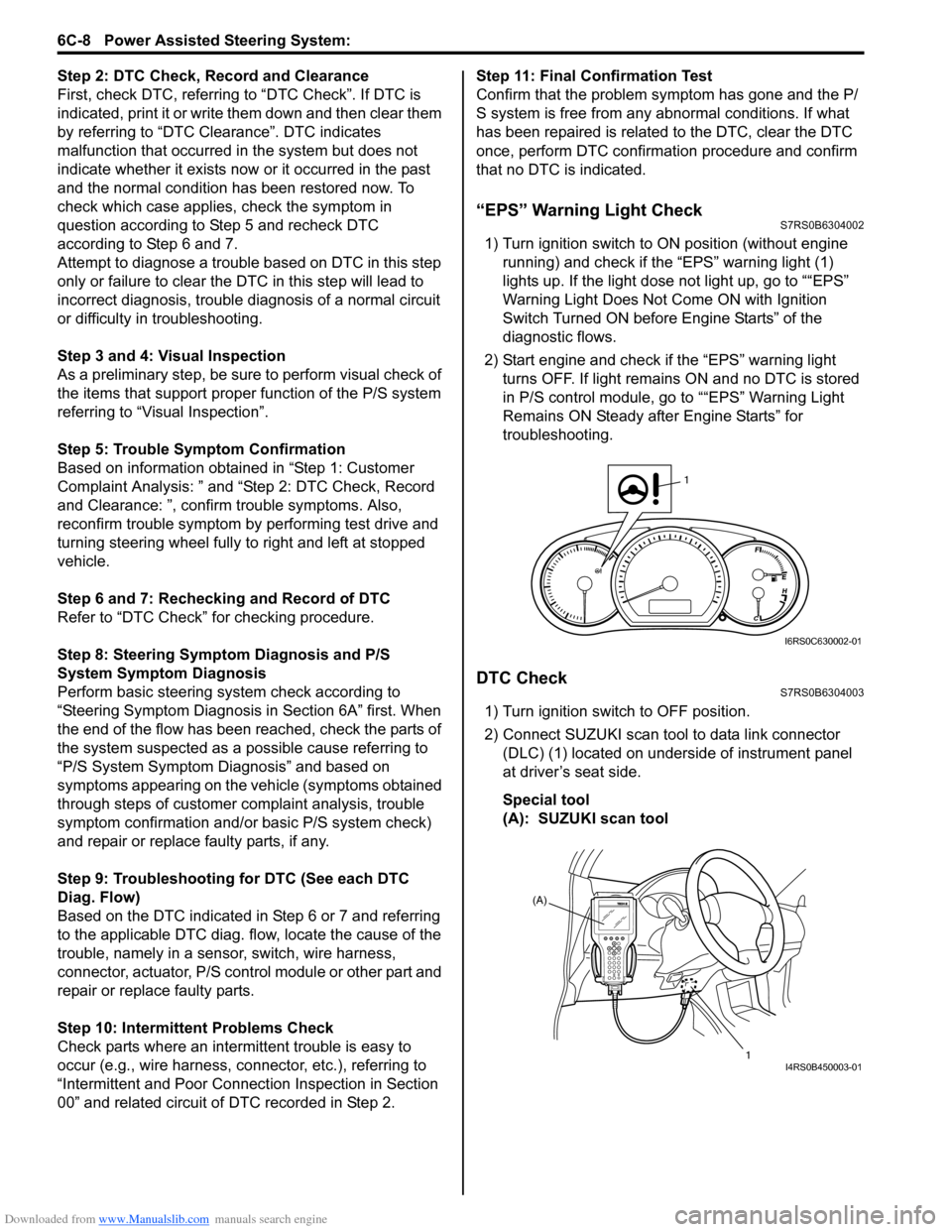
“EPS” Warning Light CheckS7RS0B6304002
1) Turn ignition switch to ON position (without engine
running) and chec k if the “EPS” warning light (1)
lights up. If the light dose not light up, go to ““EPS”
Warning Light Does Not Come ON with Ignition
Switch Turned ON before Engine Starts” of the
diagnostic flows.
2) Start engine and check if the “EPS” warning light turns OFF. If light remains ON and no DTC is stored
in P/S control module, go to ““EPS” Warning Light
Remains ON Steady after Engine Starts” for
troubleshooting.
DTC CheckS7RS0B6304003
1) Turn ignition switch to OFF position.
2) Connect SUZUKI scan tool to data link connector (DLC) (1) located on underside of instrument panel
at driver’s seat side.
Special tool
(A): SUZUKI scan tool
1
I6RS0C630002-01
(A)
1
I4RS0B450003-01
Page 894 of 1496
Downloaded from www.Manualslib.com manuals search engine 6C-12 Power Assisted Steering System:
Scan Tool Data Definitions
Battery Voltage
This parameter indicates battery positive voltage.
TQS Power Supply (Torque Sensor Power Supply, V)
This parameter indicates the power supply voltage which
the P/S control module supplies to the torque sensor.
TQS Main Torque (Torque Sensor Main Torque, N ⋅m)
The torque sensor is installed to detect the steering force
and the steering directio n. It consists of two
potentiometers and the main torque sensor is one of
these.
TQS Sub Torque (Torque Sensor Sub Torque, N ⋅m)
The torque sensor is installed to detect the steering force
and the steering directio n. It consists of two
potentiometers and the sub-torque sensor is one of
these. Its output characteristics are compared with those
of the main torque sensor.
Assist Torque (N ⋅m)
This parameter is an internal parameter of the P/S
control module. It is obtained by computing the torque
sensor input signal. Motor Control (Motor Control Current, A)
Based on the input signal, the P/S control module
determines the assist amount
and controls the current to
the motor suitable for that a ssist amount. This parameter
indicates that control value.
Motor Monitor (Motor Monitor Current, A)
This parameter indicates the actually measured value of
the current flowing to the motor. The motor circuit
condition is diagnosed by co mparing this parameter with
“Motor Control” parameter described previously.
Vehicle Speed (km/h, MPH)
Vehicle speed signal is fed from BCM. P/S control
module determines the amount of power assist based on
this vehicle speed signal and the torque sensor signal.
Engine Speed (rpm)
Engine speed signal is fed from the ECM so that it can
be used for trouble diagnos is of the electric power
steering system.
Motor Volt (V)
This parameter indicates the voltage between motor
terminals.
Ignition switch (ON, OFF)
This parameter indicates the condition of the power
supply through the ignition switch.
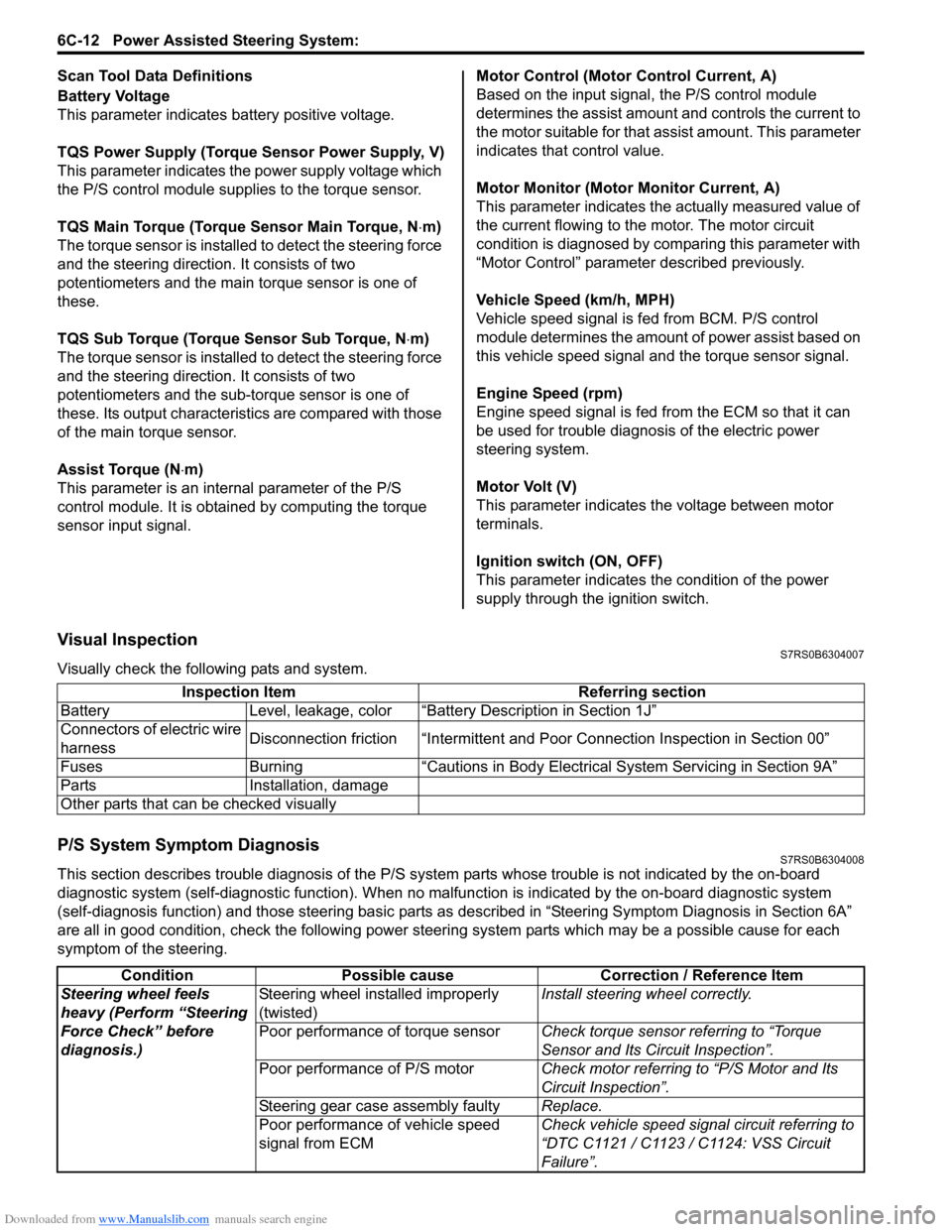
Visual InspectionS7RS0B6304007
Visually check the following pats and system.
P/S System Symptom DiagnosisS7RS0B6304008
This section describes trouble diagnosis of the P/S system parts whose trouble is not indicated by the on-board
diagnostic system (self-diagnostic functi on). When no malfunction is indicated by the on-board diagnostic system
(self-diagnosis function) and those stee ring basic parts as described in “Steering Symptom Diagnosis in Section 6A”
are all in good condition, check the following power steer ing system parts which may be a possible cause for each
symptom of the steering. Inspection Item Referring section
Battery Level, leakage, color “Batte ry Description in Section 1J”
Connectors of electric wire
harness Disconnection friction “Intermittent and Poor
Connection Inspection in Section 00”
Fuses Burning “Cautions in Body Electric al System Servicing in Section 9A”
Parts Installation, damage
Other parts that can be checked visually
Condition Possible cause Correction / Reference Item
Steering wheel feels
heavy (Perform “Steering
Force Check” before
diagnosis.) Steering wheel installed improperly
(twisted)
Install steering wheel correctly.
Poor performance of torque sensor Check torque sensor referring to “Torque
Sensor and Its Circuit Inspection”.
Poor performance of P/S motor Check motor referring to “P/S Motor and Its
Circuit Inspection”.
Steering gear case assembly faulty Replace.
Poor performance of vehicle speed
signal from ECM Check vehicle speed signal circuit referring to
“DTC C1121 / C1123 / C1124: VSS Circuit
Failure”.
Page 917 of 1496
Downloaded from www.Manualslib.com manuals search engine Power Assisted Steering System: 6C-35
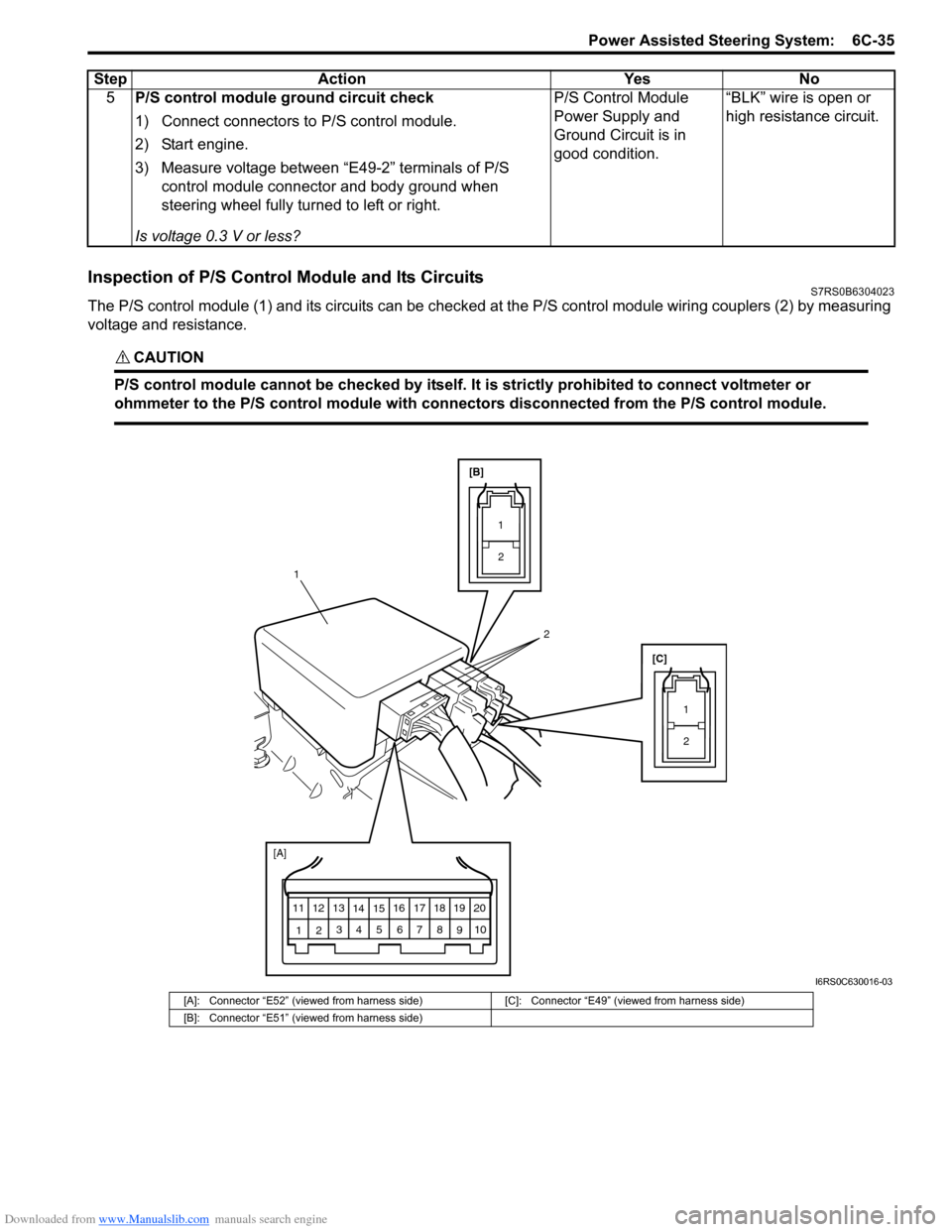
Inspection of P/S Control Module and Its CircuitsS7RS0B6304023
The P/S control module (1) and its circuits can be checked at the P/S control module wiring couplers (2) by measuring
voltage and resistance.
CAUTION!
P/S control module cannot be checked by itself. It is strictly prohibited to connect voltmeter or
ohmmeter to the P/S control module with connectors disconnected from the P/S control module.
5 P/S control module ground circuit check
1) Connect connectors to P/S control module.
2) Start engine.
3) Measure voltage between “E49-2” terminals of P/S
control module connector and body ground when
steering wheel fully turned to left or right.
Is voltage 0.3 V or less? P/S Control Module
Power Supply and
Ground Circuit is in
good condition.
“BLK” wire is open or
high resistance circuit.
Step Action Yes No
[A]
12
3
4 5 67
89
11
10
12 13
141516
17 18 19 20
[B]
[C]
12
1
1 2
2
I6RS0C630016-03
[A]: Connector “E52” (viewed from harness side) [C]: Connector “E49” (viewed from harness side)
[B]: Connector “E51” (viewed from harness side)
Page 918 of 1496
Downloaded from www.Manualslib.com manuals search engine 6C-36 Power Assisted Steering System:
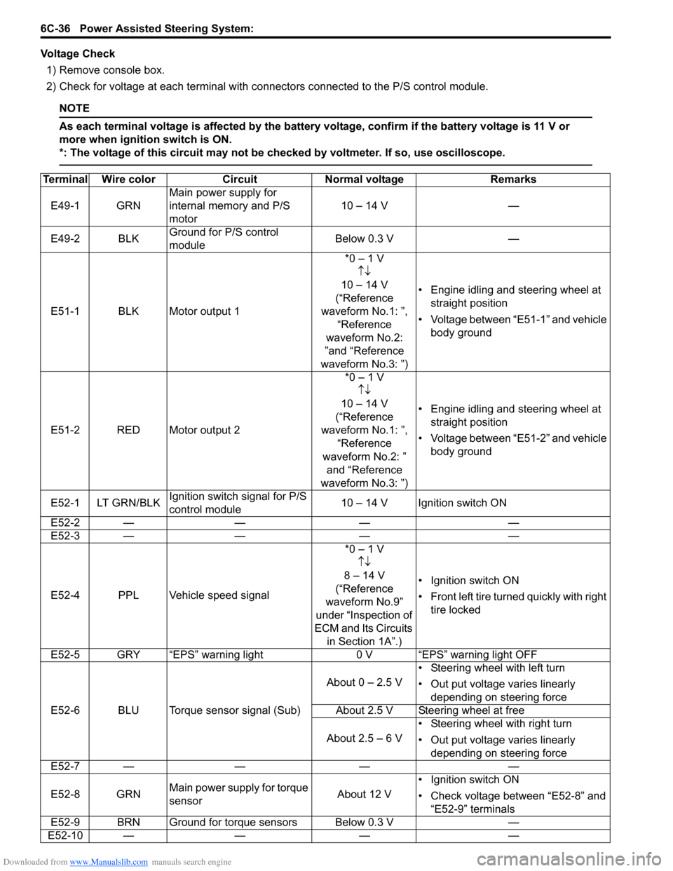
Voltage Check1) Remove console box.
2) Check for voltage at each terminal with co nnectors connected to the P/S control module.
NOTE
As each terminal voltage is affected by the battery voltage, confirm if the battery voltage is 11 V or
more when ignition switch is ON.
*: The voltage of this circuit may not be checked by voltmeter. If so, use oscilloscope.
Terminal Wire colorCircuit Normal voltage Remarks
E49-1 GRN Main power supply for
internal memory and P/S
motor 10 – 14 V
—
E49-2 BLK Ground for P/S control
module Below 0.3 V
—
E51-1 BLK Motor output 1 *0 – 1 V
↑↓
10 – 14 V
(“Reference
waveform No.1: ”, “Reference
waveform No.2:
”and “Reference
waveform No.3: ”) • Engine idling and steering wheel at
straight position
• Voltage between “E51-1” and vehicle body ground
E51-2 RED Motor output 2 *0 – 1 V
↑↓
10 – 14 V
(“Reference
waveform No.1: ”, “Reference
waveform No.2: ” and “Reference
waveform No.3: ”) • Engine idling and steering wheel at
straight position
• Voltage between “E51-2” and vehicle body ground
E52-1 LT GRN/BLK Ignition switch signal for P/S
control module 10 – 14 V Ignition switch ON
E52-2 — —— —
E52-3 — —— —
E52-4 PPL Vehicle speed signal *0 – 1 V
↑↓
8 – 14 V
(“Reference
waveform No.9”
under “Inspection of
ECM and Its Circuits in Section 1A”.) • Ignition switch ON
•Front left tire tu
rned quickly with right
tire locked
E52-5 GRY “EPS” warning light 0 V “EPS” warning light OFF
E52-6 BLU Torque sensor signal (Sub) About 0 – 2.5 V
• Steering wheel with left turn
• Out put voltage varies linearly
depending on steering force
About 2.5 V Steering wheel at free
About 2.5 – 6 V • Steering wheel with right turn
• Out put voltage varies linearly
depending on steering force
E52-7 — —— —
E52-8 GRN Main power supply for torque
sensor About 12 V• Ignition switch ON
• Check voltage between “E52-8” and
“E52-9” terminals
E52-9 BRN Ground for torque sensors Below 0.3 V —
E52-10 — —— —