wheels SUZUKI SWIFT 2005 2.G Service Workshop Manual
[x] Cancel search | Manufacturer: SUZUKI, Model Year: 2005, Model line: SWIFT, Model: SUZUKI SWIFT 2005 2.GPages: 1496, PDF Size: 34.44 MB
Page 4 of 1496

Downloaded from www.Manualslib.com manuals search engine 00
0
1
2
3
4
5
6
7
8
9
10
11
Vo l u m e 1
Precautions............................................................... 00-iPrecautions ............................................................ 00-1
General Information ................ ................................... 0-i
General Information ............................................... 0A-1
Maintenance and Lubricatio n ................................. 0B-1
Engine ......................................................................... 1-i Precautions .............................................................. 1-1
Engine General Information and Diagnosis ........... 1A-1
Aux. Emission Control Devices .............................. 1B-1
Engine Electrical Devices....................................... 1C-1
Engine Mechanical ................................................. 1D-1
Engine Lubrication System .................................... 1E-1
Engine Cooling System .......................................... 1F-1
Fuel System ...........................................................1G-1
Ignition System....................................................... 1H-1
Starting System ....................................................... 1I-1
Charging System.....................................................1J-1
Exhaust System ..................................................... 1K-1
Suspension ................................................................. 2-i Precautions .............................................................. 2-1
Suspension General Diagnosis .............................. 2A-1
Front Suspension ................................................... 2B-1
Rear Suspension................ .................................... 2C-1
Wheels and Tires ................................................... 2D-1
Driveline / Axle ........................................................... 3-i Precautions .............................................................. 3-1
Drive Shaft / Axle ................................................... 3A-1
Brakes ......................................................................... 4-i Precautions .............................................................. 4-1
Brake Control System and Diagnosis .................... 4A-1
Front Brakes........................................................... 4B-1
Rear Brakes ........................................................... 4C-1
Parking Brake......................................................... 4D-1
ABS ........................................................................ 4E-1
Electronic Stability Program ................................... 4F-1
Vo l u m e 2
Precautions ............................................................... 00-iPrecautions ............................................................ 00-1
Transmission / Transaxle .... ...................................... 5-i
Precautions .............................................................. 5-1
Automatic Transmission/Transaxle ........................ 5A-1
Manual Transmission/Transaxle ............................ 5B-1
Clutch .....................................................................5C-1
Steering ....................................................................... 6-i Precautions .............................................................. 6-1
Steering General Diagnosis ................................... 6A-1
Steering Wheel and Column .................................. 6B-1
Power Assisted Steering System ...........................6C-1
HVAC ........................................................................... 7-i Precautions .............................................................. 7-1
Heater and Ventilation............................................ 7A-1
Air Conditioning System ......................................... 7B-1
Restraint ...................................................................... 8-i Precautions .............................................................. 8-1
Seat Belts ............................................................... 8A-1
Air Bag System ...................................................... 8B-1
Body, Cab and Accessories .... .................................. 9-i
Precautions .............................................................. 9-1
Wiring Systems ...................................................... 9A-1
Lighting Systems .................................................... 9B-1
Instrumentation / Driver Info. / Horn .......................9C-1
Wipers / Washers ...................................................9D-1
Glass / Windows / Mirrors ...................................... 9E-1
Security and Locks ................................................. 9F-1
Seats ..................................................................... 9G-1
Interior Trim ............................................................9H-1
Hood / Fenders / Doors .......................................... 9J-1
Body Structure ....................................................... 9K-1
Paint / Coatings ...................................................... 9L-1
Exterior Trim .......................................................... 9M-1
Control Systems ....................................................... 10-i Precautions ............................................................ 10-1
Body Electrical Control Sy stem ............................ 10B-1
Immobilizer Control System .................................10C-1
Keyless Start System ........................................... 10E-1
TABLE OF CONTENTS
Page 5 of 1496
Downloaded from www.Manualslib.com manuals search engine Table of Contents 00- i
00
Section 00
CONTENTS
Precautions
Precautions ............................................... 00-1
Precautions........................................................... 00-1
Precautions for Vehicles Equipped with a Supplemental Restraint (A ir Bag) System ........ 00-1
General Precautions ........... ................................ 00-4
Warning for Wheel (with tire) Removal ............... 00-7
Warning for Handling Emergency Flat Tire Repair Kit .......................................................... 00-7
Precautions for Catalytic Converter .................... 00-7
Precautions for Installing Mobile Communication Equipment ............................... 00-7
Precaution for CAN Communication System ...... 00-7 Precautions for Electrical Circuit Service ............ 00-8
Air Bag Warning ................................................ 00-10
Air Bag System Service Warning ...................... 00-10
Fastener Caution............................................... 00-10
Suspension Caution .......................................... 00-10
Wheels and Tires Caution ................................. 00-10
Precaution for Vehicle Equipped with ESP
®
System ............................................................ 00-11
Brake Caution ................................................... 00-11
Repair Instructions ........ .................................... 00-11
Electrical Circuit Inspection Procedure ............. 00-11
Intermittent and Poor Co nnection Inspection .... 00-13
Page 12 of 1496
Downloaded from www.Manualslib.com manuals search engine 00-7 Precautions:
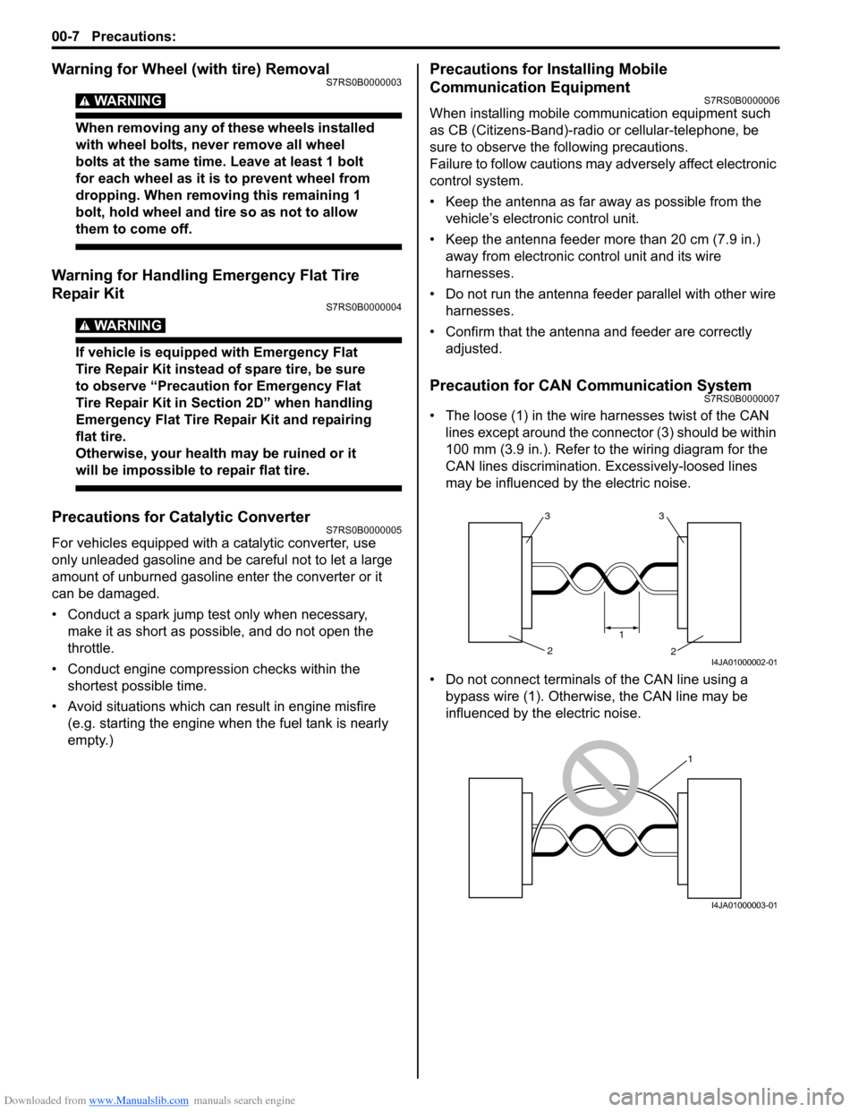
Warning for Wheel (with tire) RemovalS7RS0B0000003
WARNING!
When removing any of these wheels installed
with wheel bolts, never remove all wheel
bolts at the same time. Leave at least 1 bolt
for each wheel as it is to prevent wheel from
dropping. When removing this remaining 1
bolt, hold wheel and tire so as not to allow
them to come off.
Warning for Handling Emergency Flat Tire
Repair Kit
S7RS0B0000004
WARNING!
If vehicle is equipped with Emergency Flat
Tire Repair Kit instead of spare tire, be sure
to observe “Precaution for Emergency Flat
Tire Repair Kit in Section 2D” when handling
Emergency Flat Tire Repair Kit and repairing
flat tire.
Otherwise, your health may be ruined or it
will be impossible to repair flat tire.
Precautions for Catalytic ConverterS7RS0B0000005
For vehicles equipped with a catalytic converter, use
only unleaded gasoline and be careful not to let a large
amount of unburned gasoline enter the converter or it
can be damaged.
• Conduct a spark jump test only when necessary, make it as short as possible, and do not open the
throttle.
• Conduct engine compression checks within the shortest possible time.
• Avoid situations which can result in engine misfire (e.g. starting the engine when the fuel tank is nearly
empty.)
Precautions for Installing Mobile
Communication Equipment
S7RS0B0000006
When installing mobile communication equipment such
as CB (Citizens-Band)-radi o or cellular-telephone, be
sure to observe the following precautions.
Failure to follow cautions may adversely affect electronic
control system.
• Keep the antenna as far away as possible from the vehicle’s electronic control unit.
• Keep the antenna feeder more than 20 cm (7.9 in.) away from electronic control unit and its wire
harnesses.
• Do not run the antenna feeder parallel with other wire harnesses.
• Confirm that the antenna and feeder are correctly adjusted.
Precaution for CAN Communication SystemS7RS0B0000007
• The loose (1) in the wire harnesses twist of the CAN lines except around the connector (3) should be within
100 mm (3.9 in.). Refer to the wiring diagram for the
CAN lines discrimination. Excessively-loosed lines
may be influenced by the electric noise.
• Do not connect terminals of the CAN line using a bypass wire (1). Otherwise, the CAN line may be
influenced by the electric noise.
33
2
2
1
I4JA01000002-01
1
I4JA01000003-01
Page 15 of 1496
Downloaded from www.Manualslib.com manuals search engine Precautions: 00-10
Air Bag WarningS7RS0B0000009
WARNING!
For vehicles equipped with Supplemental
Restraint (Air Bag) System:
• Service on and around the air bag system components or wiring must be performed
only by an authorized SUZUKI dealer. Refer
to “Air Bag System Components, Wiring
and Connectors Location in Section 8B” in
order to confirm whether you are
performing service on or near the air bag
system components or wiring. Please
observe all WARNINGS in Air Bag System
section and “Precautions on Service and
Diagnosis of Air Bag System in Section
8B” before performing service on or
around the air bag system components or
wiring. Failure to follow WARNINGS could
result in unintentional activation of the
system or could render the system
inoperative. Either of these two conditions
may result in severe injury.
• Technical service work must be started at least 90 seconds after the ignition switch is
turned to the LOCK position and the
negative cable is disconnected from the
battery. Otherwise, the system may be
activated by reserve energy in the Sensing
and Diagnostic Module (SDM).
Air Bag System Service WarningS7RS0B0000010
WARNING!
• Service on or around the air bag system components or wiring must be performed
only by an authorized SUZUKI dealer.
Please observe all WARNINGS in Air Bag
System section and “Precautions on
Service and Diagnosis of Air Bag System
in Section 8B” before performing service
on or around the air bag system
components or wiring. Failure to follow
WARNINGS could result in unintended
activation of the system or could render
the system inoperative. Either of these two
conditions may result in severe injury.
• The procedures in the air bag system section must be followed in the order
listed to disable the air bag system
temporarily and prevent false DTCs from
setting. Failure to follow procedures could
result in possible activation of the air bag
system, personal injury or otherwise
unneeded air bag system repairs.
Fastener CautionS7RS0B0000011
CAUTION!
When fasteners are removed, always reinstall
them at the same location from which they
were removed. If a fastener needs to be
replaced, use the correct part number
fastener for that application. If the correct
part number fastener is not available, a
fastener of equal size and strength (or
stronger) may be used. Fasteners that are not
reused, and those requiring thread-locking
compound, will be called out. The correct
torque value must be used when installing
fasteners that require it. If the conditions are
not followed, parts or system damage could
result.
Suspension CautionS7RS0B0000012
CAUTION!
• All suspension fasteners are an important attaching part in that it could affect the
performance of vital parts and systems,
and/or could result in major repair
expense. They must be replaced with one
of the same part number or with an
equivalent part if replacement becomes
necessary. Do not use a replacement part
of lesser quality or substitute design.
Torque values must be used as specified
during reassembly to assure proper
retention of this part.
• Never attempt to heat, quench or straighten any suspension part. Replace it
with a new part or damage to the part may
result.
Wheels and Tires CautionS7RS0B0000013
CAUTION!
All wheel fasteners are important attaching
parts in that they could affect the
performance of vital parts and systems, and/
or could result in major repair expense. They
must be replaced with one of the same part
number or with an eq uivalent part if
replacement becomes necessary. Do not use
a replacement part of lesser quality or
substitute design. Torque values must be
used as specified during reassembly to
assure proper retention of all parts.
There is to be no welding as it may result in
extensive damage and weakening of the
metal.
Page 16 of 1496
Downloaded from www.Manualslib.com manuals search engine 00-11 Precautions:
Precaution for Vehicle Equipped with ESP®
System
S7RS0B0000015
• When testing with any of the following equipments
(when vehicle is tested by rotating wheels (tires)
under vehicle stop), be sure to deactivate ESP ®
system referring to “Precautions in Speedometer Test
or Other Tests in Section 4F” to obtain correct data.
– 2 or 4-wheel chassis dynamometer
– Speedometer tester
– Brake tester
–Etc.
ESP ® control module
• When ESP ® control module is removed / installed, do
not use impact wrenches which generate shock or
impact to avoid damaging sensors in ESP ® control
module.
• When any of the following operation is done, calibrate steering angle sensor referring to “Sensor Calibration
in Section 4F”.
– When battery or dome fuse is removed.
– When steering angle sensor is replaced.
Brake CautionS7RS0B0000014
CAUTION!
All brake fasteners are important attaching
parts in that they could affect the
performance of vital parts and systems, and/
or could result in major repair expense. They
must be replaced with one of same part
number or with an eq uivalent part if
replacement becomes necessary. Do not use
a replacement part of lesser quality or
substitute design. Torque values must be
used as specified during reassembly to
assure proper retention of all parts. There is
to be no welding as it may result in extensive
damage and weakening of the metal.
Repair Instructions
Electrical Circuit Inspection ProcedureS7RS0B0006001
While there are various electrical circuit inspection
methods, described here is a general method to check
its open and short circuit by using an ohmmeter and a
voltmeter.
Open Circuit Check
Possible causes for the open circuit are as follows. As
the cause is in the connector or terminal in many cases,
they need to be checked particularly carefully.
• Loose connection of connector
• Poor contact of terminal (due to dirt, corrosion or rust
on it, poor contact tension, entry of foreign object etc.)
• Wire harness being open
When checking system circuits including an electronic
control unit such as ECM, TCM, ABS control module,
etc., it is important to perfor m careful check, starting with
items which are easier to check.
1) Disconnect negative (–) cable from battery
2) Check each connector at both ends of the circuit being checked for loose connection. Also check lock
condition of connector if equipped with connector
lock. 3) Using a test male terminal
, check both terminals of
the circuit being checked for contact tension of its
female terminal. Check each terminal visually for
poor contact (possibly caused by dirt, corrosion, rust
entry of foreign object, etc.). At the same time, check
to make sure that each te rminal is locked in the
connector fully.
1. Check contact tension by inserting and removing just for once.
I2RH01010049-01
I2RH01010050-01
Page 27 of 1496
Downloaded from www.Manualslib.com manuals search engine General Information: 0A-6
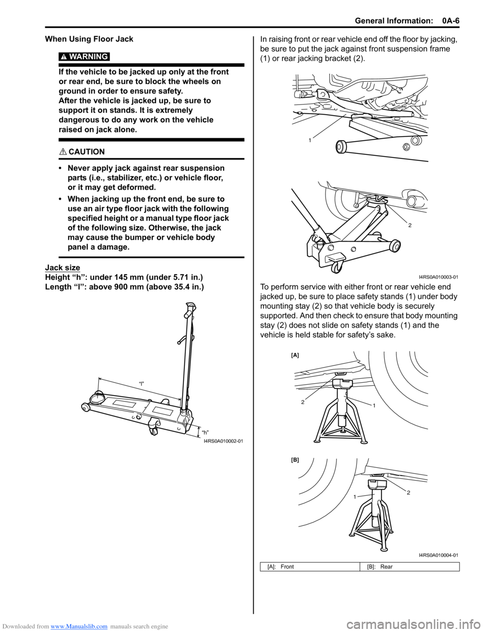
When Using Floor Jack
WARNING!
If the vehicle to be jacked up only at the front
or rear end, be sure to block the wheels on
ground in order to ensure safety.
After the vehicle is jacked up, be sure to
support it on stands. It is extremely
dangerous to do any work on the vehicle
raised on jack alone.
CAUTION!
• Never apply jack against rear suspension parts (i.e., stabilizer, etc.) or vehicle floor,
or it may get deformed.
• When jacking up the front end, be sure to use an air type floor jack with the following
specified height or a manual type floor jack
of the following size. Otherwise, the jack
may cause the bumper or vehicle body
panel a damage.
Jack size
Height “h”: under 145 mm (under 5.71 in.)
Length “l”: above 900 mm (above 35.4 in.) In raising front or rear vehicl
e end off the floor by jacking,
be sure to put the jack a gainst front suspension frame
(1) or rear jacking bracket (2).
To perform service with either front or rear vehicle end
jacked up, be sure to place safety stands (1) under body
mounting stay (2) so that vehicle body is securely
supported. And then check to ensure that body mounting
stay (2) does not slide on safety stands (1) and the
vehicle is held stable for safety’s sake.
“h”
“l”
I4RS0A010002-01
[A]: Front
[B]: Rear
2
1
I4RS0A010003-01
1
1
2
2
[B] [A]
I4RS0A010004-01
Page 31 of 1496
Downloaded from www.Manualslib.com manuals search engine Maintenance and Lubrication: 0B-1
General Information
Maintenance and Lubrication
Precautions
Precautions for Maintenance and LubricationS7RS0B0200001
Air Bag Warning
Refer to “Air Bag Warning in Section 00”.
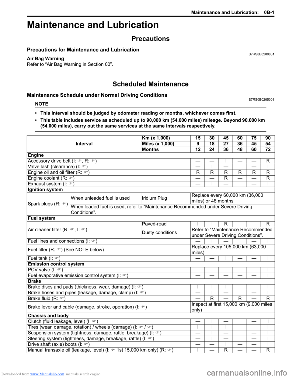
Scheduled Maintenance
Maintenance Schedule under Normal Driving ConditionsS7RS0B0205001
NOTE
• This interval should be judged by odometer reading or months, whichever comes first.
• This table includes service as scheduled up to 90,000 km (54,000 miles) mileage. Beyond 90,000 km
(54,000 miles), carry out the same services at the same intervals respectively.
Interval Km (x 1,000) 15 30 45 60 75 90
Miles (x 1,000) 9 18 27 36 45 54
Months 12 24 36 48 60 72
Engine
Accessory drive belt (I: �), R: �))——I——R
Valve lash (clearance) (I: �)) —I—I—I
Engine oil and oil filter (R: �)) RRRRRR
Engine coolant (R: �))— —R— — R
Exhaust system (I: �)) —I—I—I
Ignition system
Spark plugs (R: �) )When unleaded fuel is used Iridium Plug
Replace every 60,000 km (36,000
miles) or 48 months
When leaded fuel is used, refer to “Maintenance Recommended under Severe Driving
Conditions”.
Fuel system
Air cleaner filter (R: �), I: �)) Paved-road
I I R I I R
Dusty conditions Refer to “Maintenance Recommended
under Severe Driv
ing Conditions”.
Fuel lines and connections (I: �)) —I—I—I
Fuel filter (R: �)) (See NOTE below) Replace every 105,000 km (63,000
miles)
Fuel tank (I: �))— —I— — I
Emission control system
PCV valve (I: �)) ————— I
Fuel evaporative emission control system (I: �)) ————— I
Brake
Brake discs and pads (thickness, wear, damage) (I: �)) IIIIII
Brake hoses and pipes (leakage, damage, clamp) (I: �)) —I—I—I
Brake fluid (R: �)) —R—R—R
Brake lever and cable (damage, stroke, operation) (I: �)) Inspect at first 15,000 km (9,000 miles
only)
Chassis and body
Clutch (fluid leakage, level) (I: �)) —I—I—I
Tires (wear, damage, rotation) / wheels (damage) (I: �) / �) ) IIIIII
Suspension system (tightness, damage, rattle, breakage) (I: �)) —I—I—I
Steering system (tightness, damage, breakage, rattle) (I: �)) —I—I—I
Drive shaft (axle) boots (I: �))— —I— — I
Manual transaxle oil (leakage, level) (I: �) 1st 15,000 km only) (R: �))I—R——R
Page 43 of 1496
Downloaded from www.Manualslib.com manuals search engine Maintenance and Lubrication: 0B-13
Brake
Foot brake
Check the following:
• that brake pedal has proper travel,
• that brake works properly,
• that it is free from noise,
• that vehicle does not pull to one side when brake is applied.
• and that brake do not drag.
Parking brake
Check that lever has proper travel.
WARNING!
With vehicle parked on a fairly steep slope,
make sure nothing is in the way downhill to
avoid any personal injury or property
damage. Be prepared to apply regular brake
quickly even if vehicle should start to move.
Check to ensure that parking brake is fully effective
when the vehicle is stopped on the safe slope and brake
lever is pulled all the way.
Steering
• Check to ensure that steering wheel is free from instability, or abnormally heavy feeling. • Check that the vehicle does not wander or pull to one
side.
Engine
• Check that engine responds readily at all speeds.
• Check that engine is free from abnormal noise and abnormal vibration.
Body, Wheels and Power Transmitting System
Check that body, wheels and power transmitting system
are free from abnormal noise and abnormal vibration or
any other abnormal condition.
Meters and Gauge
Check that speedometer, odometer, fuel meter,
temperature gauge, etc. are operating accurately.
Lights
Check that all lights operate properly.
Windshield Defroster
Periodically check that ai r comes out from defroster
outlet when operating heater or air conditioning.
Set mode control lever to defroster position and fan
switch lever to “HI” position for this check.
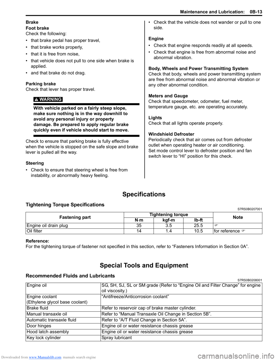
Specifications
Tightening Torque SpecificationsS7RS0B0207001
Reference:
For the tightening torque of fastener not specified in this section, refer to “Fasteners Information in Section 0A”.
Special Tools and Equipment
Recommended Fluids and LubricantsS7RS0B0208001
Fastening part Tightening torque
Note
N ⋅mkgf-mlb-ft
Engine oil drain plug 35 3.5 25.5 �)
Oil filter 14 1.4 10.5 for reference �)
Engine oilSG, SH, SJ, SL or SM grade (Refer to “Engine Oil and Filter Change” for engine
oil viscosity.)
Engine coolant
(Ethylene glycol base coolant) “Antifreeze/Antico
rrosion coolant”
Brake fluid Refer to reservoir cap of brake master cylinder.
Manual transaxle oil Refer to “Manual Transaxle Oil Change in Section 5B”.
Automatic transaxle fluid Refer to “A/T Fluid Change in Section 5A”.
Door hinges Engine oil or water resistance chassis grease
Hood latch assembly Engine oil or water resistance chassis grease
Key lock cylinder Spray lubricant
Page 266 of 1496
Downloaded from www.Manualslib.com manuals search engine 1A-216 Engine General Information and Diagnosis:
Repair Instructions
Idle Speed and IAC Throttle Valve Opening
Inspection
S7RS0B1106001
Before idle speed check, make sure of the following.
• Lead wires and hoses of electronic fuel injection and engine and emission control systems are connected
securely.
• Valve lash is checked according to maintenance schedule.
• Ignition timing is within specification.
• All accessories (wipers, heater, lights, A/C, etc.) are out of service.
• Air cleaner has been properly installed and is in good condition.
• No abnormal air drawn in from air intake system.
After all items are confirmed, check idle speed and IAC
duty as follows.
NOTE
Before starting engine, place transmission
gear shift lever in “Neutral” (shift selector
lever to “P” range for A/T vehicle), and set
parking brake and block drive wheels.
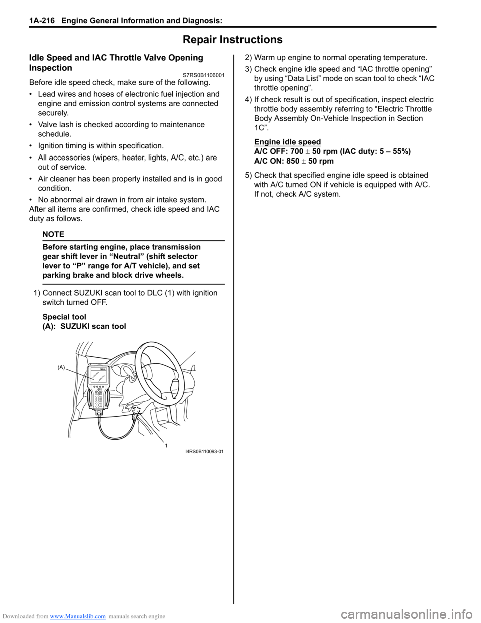
1) Connect SUZUKI scan tool to DLC (1) with ignition
switch turned OFF.
Special tool
(A): SUZUKI scan tool 2) Warm up engine to normal operating temperature.
3) Check engine idle speed and “IAC throttle opening”
by using “Data List” mode on scan tool to check “IAC
throttle opening”.
4) If check result is out of sp ecification, inspect electric
throttle body assembly referring to “Electric Throttle
Body Assembly On-Vehicle Inspection in Section
1C”.
Engine idle speed
A/C OFF: 700 ± 50 rpm (IAC duty: 5 – 55%)
A/C ON: 850 ± 50 rpm
5) Check that specified engine idle speed is obtained with A/C turned ON if vehi cle is equipped with A/C.
If not, check A/C system.
(A)
1
I4RS0B110093-01
Page 289 of 1496
Downloaded from www.Manualslib.com manuals search engine Engine Mechanical: 1D-4
Targeted Timing Varying Operation
Diagnostic Information and Procedures
Compression CheckS7RS0B1404001
Check compression pressure on all 4 cylinders as
follows:
1) Warm up engine to normal operating temperature.
2) Stop engine after warming up.
NOTE
After warming up engine, place transaxle
gear shift lever in “Neutral”, and set parking
brake and block drive wheels.
3) Disconnect negative cable at battery.
4) Remove engine cover.
5) Remove air cleaner assembly and air suction hose referring to “Air Cleaner Components”.
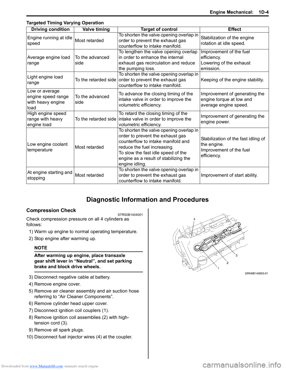
6) Remove cylinder head upper cover.
7) Disconnect ignition coil couplers (1).
8) Remove ignition coil assemblies (2) with high- tension cord (3).
9) Remove all spark plugs.
10) Disconnect fuel injector wires (4) at the coupler. Driving condition Valve timing Target of control Effect
Engine running at idle
speed Most retardedTo shorten the valve opening overlap in
order to prevent the exhaust gas
counterflow to in
take manifold. Stabilization of the engine
rotation at idle speed.
Average engine load
range To the advanced
sideTo lengthen the valve opening overlap
in order to enhance the internal
exhaust gas recirculation and reduce
the pumping loss. Improvement of the fuel
efficiency.
Lowering of the exhaust
emission.
Light engine load
range To the retarded sideTo shorten the valve opening overlap in
order to prevent the exhaust gas
counterflow to in
take manifold. Keeping of the engine stability.
Low or average
engine speed range
with heavy engine
load To the advanced
side
To advance the closing timing of the
intake valve in order to improve the
volumetric efficiency. Improvement of generating the
engine torque at low and
average engine speed.
High engine speed
range with heavy
engine load To the retarded sideTo retard the closing timing of the
intake valve in order to improve the
volumetric efficiency. Improvement of generating the
engine power.
Low engine coolant
temperature Most retardedTo shorten the valve opening overlap in
order to prevent the exhaust gas
counterflow to intake manifold and
reduce the fuel increasing.
To slow the fast idle speed of the
engine as a result of stabilizing the
engine idling. Stabilization of the fast idling of
the engine.
Improvement of the fuel
efficiency.
At engine starting and
stopping Most retardedTo shorten the valve opening overlap in
order to prevent the exhaust gas
counterflow to in
take manifold. Improvement of start ability.I2RH0B140003-01