Air bag connection SUZUKI SWIFT 2006 2.G Service Workshop Manual
[x] Cancel search | Manufacturer: SUZUKI, Model Year: 2006, Model line: SWIFT, Model: SUZUKI SWIFT 2006 2.GPages: 1496, PDF Size: 34.44 MB
Page 7 of 1496
Downloaded from www.Manualslib.com manuals search engine Precautions: 00-2
Servicing and Handling
WARNING!
Many of service procedures require
disconnection of “A/BAG” fuse and all air
bag (inflator) module(s) from initiator circuit
to avoid an accidental deployment.
Driver, Passenger, Side and Curtain Air Bag
(Inflator) Modules
• For handling and storage of a live air bag (inflator) module, select a place where the
ambient temperature below 65 °C (150 ° F),
without high humidity and away from
electric noise.
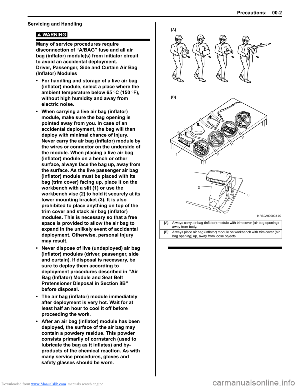
• When carrying a live air bag (inflator) module, make sure the bag opening is
pointed away from you. In case of an
accidental deployment, the bag will then
deploy with minimal chance of injury.
Never carry the air bag (inflator) module by
the wires or connector on the underside of
the module. When placing a live air bag
(inflator) module on a bench or other
surface, always face the bag up, away from
the surface. As the live passenger air bag
(inflator) module must be placed with its
bag (trim cover) facing up, place it on the
workbench with a slit (1) or use the
workbench vise (2) to hold it securely at its
lower mounting bracket (3). It is also
prohibited to place anything on top of the
trim cover and stack air bag (inflator)
modules. This is necessary so that a free
space is provided to allow the air bag to
expand in the unlikely event of accidental
deployment. Otherwise, personal injury
may result.
• Never dispose of live (undeployed) air bag (inflator) modules (driver, passenger, side
and curtain). If disposal is necessary, be
sure to deploy them according to
deployment procedures described in “Air
Bag (Inflator) Module and Seat Belt
Pretensioner Disposal in Section 8B”
before disposal.
• The air bag (inflator) module immediately
after deployment is very hot. Wait for at
least half an hour to cool it off before
proceeding the work.
• After an air bag (inflator) module has been deployed, the surface of the air bag may
contain a powdery residue. This powder
consists primarily of cornstarch (used to
lubricate the bag as it inflates) and by-
products of the chemical reaction. As with
many service procedures, gloves and
safety glasses should be worn.
[A]: Always carry air bag (inflator) module with trim cover (air bag opening) away from body.
[B]: Always place air bag (inflator) module on workbench with trim cover (air bag opening) up, away from loose objects.
1
2
3
[A]
[B]
I4RS0A000003-02
Page 31 of 1496
Downloaded from www.Manualslib.com manuals search engine Maintenance and Lubrication: 0B-1
General Information
Maintenance and Lubrication
Precautions
Precautions for Maintenance and LubricationS7RS0B0200001
Air Bag Warning
Refer to “Air Bag Warning in Section 00”.
Scheduled Maintenance
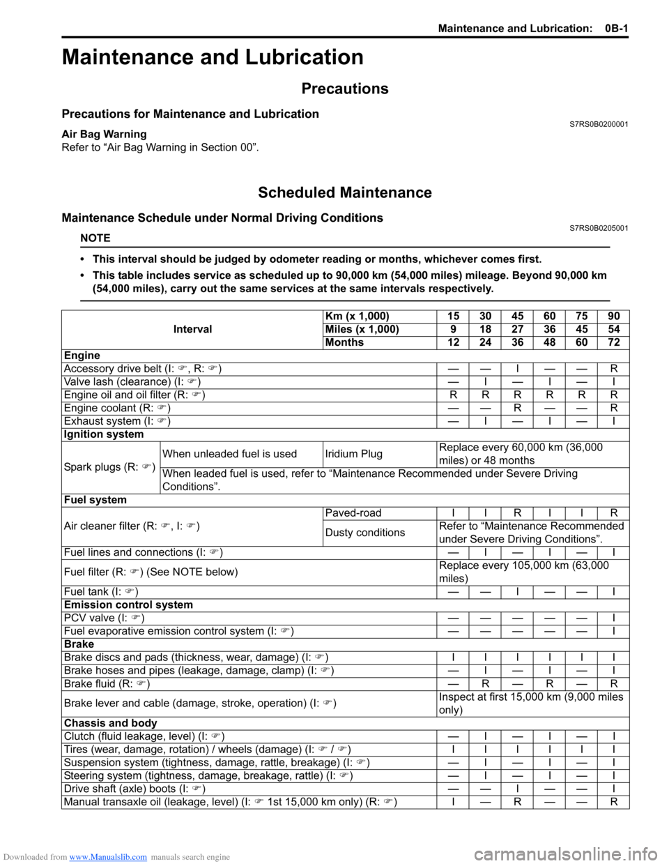
Maintenance Schedule under Normal Driving ConditionsS7RS0B0205001
NOTE
• This interval should be judged by odometer reading or months, whichever comes first.
• This table includes service as scheduled up to 90,000 km (54,000 miles) mileage. Beyond 90,000 km
(54,000 miles), carry out the same services at the same intervals respectively.
Interval Km (x 1,000) 15 30 45 60 75 90
Miles (x 1,000) 9 18 27 36 45 54
Months 12 24 36 48 60 72
Engine
Accessory drive belt (I: �), R: �))——I——R
Valve lash (clearance) (I: �)) —I—I—I
Engine oil and oil filter (R: �)) RRRRRR
Engine coolant (R: �))— —R— — R
Exhaust system (I: �)) —I—I—I
Ignition system
Spark plugs (R: �) )When unleaded fuel is used Iridium Plug
Replace every 60,000 km (36,000
miles) or 48 months
When leaded fuel is used, refer to “Maintenance Recommended under Severe Driving
Conditions”.
Fuel system
Air cleaner filter (R: �), I: �)) Paved-road
I I R I I R
Dusty conditions Refer to “Maintenance Recommended
under Severe Driv
ing Conditions”.
Fuel lines and connections (I: �)) —I—I—I
Fuel filter (R: �)) (See NOTE below) Replace every 105,000 km (63,000
miles)
Fuel tank (I: �))— —I— — I
Emission control system
PCV valve (I: �)) ————— I
Fuel evaporative emission control system (I: �)) ————— I
Brake
Brake discs and pads (thickness, wear, damage) (I: �)) IIIIII
Brake hoses and pipes (leakage, damage, clamp) (I: �)) —I—I—I
Brake fluid (R: �)) —R—R—R
Brake lever and cable (damage, stroke, operation) (I: �)) Inspect at first 15,000 km (9,000 miles
only)
Chassis and body
Clutch (fluid leakage, level) (I: �)) —I—I—I
Tires (wear, damage, rotation) / wheels (damage) (I: �) / �) ) IIIIII
Suspension system (tightness, damage, rattle, breakage) (I: �)) —I—I—I
Steering system (tightness, damage, breakage, rattle) (I: �)) —I—I—I
Drive shaft (axle) boots (I: �))— —I— — I
Manual transaxle oil (leakage, level) (I: �) 1st 15,000 km only) (R: �))I—R——R
Page 1030 of 1496
Downloaded from www.Manualslib.com manuals search engine 8-ii Table of Contents
DTC B1062 / B1066: Driver / Passenger Side-Air Bag Initiator Circuit Resistance Low .......... 8B-67
DTC B1063 / B1067: Driver / Passenger Side- Air Bag Initiator Circuit S hort to Ground .......... 8B-70
DTC B1064 / B1068: Driver / Passenger Side- Air Bag Initiator Circu it Short to Power
Circuit .............................................................. 8B-73
DTC B1071: Forward-Sensor Performance Problem ........................................................... 8B-76
DTC B1072: Forward-Sensor Communication Error ................................................................ 8B-76
DTC B1073: Forward-Sensor Circuit Short to Ground ............................................................ 8B-76
DTC B1074: Forward-Sensor Circuit Short to Power Circuit or Open ..................................... 8B-78
DTC B1081 / B1091: Driver / Passenger Side- Sensor Performance Probl em ......................... 8B-80
DTC B1082 / B1092: Driver / Passenger Side- Sensor Communication Erro r .......................... 8B-80
DTC B1083 / B1093: Driver / Passenger Side- Sensor Circuit Short to Ground ....................... 8B-80
DTC B1084 / B1094: Driver / Passenger Side- Sensor Circuit Short to Power Circuit or
Open ............................................................... 8B-81
DTC B1085 / B1095: Wrong Side-Sensor (Driver Side / Passenger) ID ........................... 8B-83
DTC B1361 / B1365: Driver / Passenger Side Curtain-Air Bag Initiator Circuit Resistance
High ................................................................. 8B-84
DTC B1362 / B1366: Driver / Passenger Side Curtain-Air Bag Initiator Circuit Resistance
Low ................................................................. 8B-86
DTC B1363 / B1367: Driver / Passenger Side Curtain-Air Bag Initiator Circuit Short to
Ground ............................................................ 8B-88
DTC B1364 / B1368: Driver / Passenger Side Curtain-Air Bag Initiator Circuit Short to
Power Circuit ................................................... 8B-90
Contact Coil Cable and Its Circuit Check .......... 8B-93 Inspection of Intermittent and Poor
Connections .................................................... 8B-95
Repair and Inspection Required after Accident .......................................................... 8B-96
Repair Instructions ............ ................................8B-98
Disabling Air Bag System.................................. 8B-98
Enabling Air Bag System .................................. 8B-99
SDM Removal and Installation ........................ 8B-100
SDM Inspection ............................................... 8B-101
Driver Air Bag (Inflato r) Module Removal and
Installation ..................................................... 8B-101
Driver Air Bag (Inflator) Module Inspection ..... 8B-103
Passenger Air Bag (Inflator) Module Removal and Installation .............................................. 8B-103
Passenger Air Bag (I nflator) Module
Inspection ...................................................... 8B-105
Side-Air Bag (Inflator) Module Removal and
Installation ..................................................... 8B-105
Side-Air Bag (Inflator) Inspection .................... 8B-107
Side Curtain-Air Bag (Inflator) Module Removal and Installation ............................... 8B-107
Side Curtain-Air Bag (Inflator) Module Inspection ...................................................... 8B-109
Forward-Sensor Removal and Installation ...... 8B-109
Forward-Sensor In spection ............................. 8B-110
Side-Sensor Removal and Installation ............ 8B-110
Side-Sensor Inspection ................................... 8B-111
Passenger Air Bag (Inflator) Module Repair
Harness Installation....................................... 8B-112
Air Bag (Inflator) Module and Seat Belt Pretensioner Disposal ................................... 8B-113
Deployed Air Bag (Inflator) Module and Activated Seat Belt Pretensioner Disposal.... 8B-124
Specifications .................. .................................8B-125
Tightening Torque Specifications .................... 8B-125
Special Tools and Equipmen t .........................8B-125
Use of Special Tools ....................................... 8B-125
Recommended Service Material ..................... 8B-127
Special Tool .................................................... 8B-127
Page 1039 of 1496
Downloaded from www.Manualslib.com manuals search engine Air Bag System: 8B-1
Restraint
Air Bag System
Precautions
Precautions on Service and Diagnosis of Air
Bag System
S7RS0B8200001
WARNING!
• If the air bag system and another vehicle system both need repair, SUZUKI
recommends that the air bag system be
repaired first, to help avoid unintended air
bag system activation.
• Do not modify the steering wheel, dashboard, both front seat or any other on
or around air bag system components.
Modifications can adversely affect air bag
system performance and lead to injury.
• Be sure to follow the procedures described in this section. Failure to follow
procedures could result in possible air bag
system activation, personal injury or
unneeded air bag system repairs.
• WARNING / CAUTION labels are attached on each
part of air bag system components (SDM, air bag
(inflator) modules and seat belt pretensioners). Be
sure to follow the instructions.
• Many of service procedures require disconnection of
“A/BAG” fuse and air bag (inflator) module(s) (driver,
passenger, side of both si des and curtain of both
sides) from initiator circuit to avoid an accidental
deployment.
• Do not apply power to the air bag system unless all components are connected or a diagnostic flow
requests it, as this will set a DTC.
• The “Air Bag Diagnostic S ystem Check” must be the
starting point of any air bag diagnostics. The “Air Bag
Diagnostic System Check” will verify proper “AIR
BAG” warning right operatio n and will lead you to the
correct flow to diagnose any air bag malfunctions.
Bypassing these procedures may result in extended
diagnostic time, incorrect diagnosis, and incorrect
parts replacements. • Never use air bag component parts from another
vehicle.
• If the vehicle will be exposed to temperatures over 93
° C (200 °F) (for example, during a paint baking
process), remove the air bag system components
beforehand to avoid component damage or
unintended system activation.
• When handling the air bag (inflator) modules (driver, passenger, side of both si des and curtain of both
sides), seat belt pretensio ners (driver and passenger),
SDM, forward-sensor or side-sensor, be careful not to
drop it or apply an impact to it. If an excessive impact
was applied (e.g., SDM, forward-sensor and side-
sensor are dropped, air bag (inflator) module is
dropped from a height of 90 cm (3 ft) or more, seat
belt pretensioner (retractor assembly) is dropped from
a height of 30 cm (1 ft) or more), never attempt
disassembly or repair but replace it with a new one.
• When using electric welding, be sure to disconnect air bag (inflator) module connectors (driver, passenger,
side of both sides and curtain of both sides) and seat
belt pretensioner connectors (driver and passenger)
respectively.
• When applying paint around the air bag system related parts, use care so that the harness or
connector will not be expo sed to the paint mist.
• Never expose air bag system component parts directly to hot air (drying or baking the vehicle after
painting) or flames.
WARNING!
When performing service on or around air
bag system components or air bag wiring,
follow the procedures listed in “Disabling Air
Bag System” to temporarily disable the air
bag system.
Failure to follow procedures could result in
possible air bag system activation, personal
injury or unneeded air bag system repairs.
Page 1049 of 1496
Downloaded from www.Manualslib.com manuals search engine Air Bag System: 8B-11
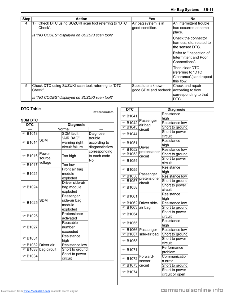
DTC TableS7RS0B8204003
SDM DTC4 1) Check DTC using SUZUKI scan tool referring to “DTC
Check”.
Is “NO CODES” displayed on SUZUKI scan tool? Air bag system is in
good condition.
An intermittent trouble
has occurred at some
place.
Check the connector
harness, etc. related to
the sensed DTC.
Refer to “Inspection of
Intermittent and Poor
Connections”.
Then clear DTC
(referring to “DTC
Clearance”.) and repeat
this flow.
5 Check DTC using SUZUKI scan tool, referring to “DTC Check”.
Is “NO CODES” displayed on SUZUKI scan tool? Substitute a known-
good SDM and recheck.
Check and repair
according to flow
corresponding to that
DTC.
Step Action Yes No
DTC
Diagnosis
—N orm al —
�) B1013
SDM SDM fault Diagnose
trouble
according to
diagnostic flow
corresponding
to each code
No.
�)
B1014 “AIR BAG”
warning right
circuit failure
�) B1016 Power
source
voltage Too high
�) B1017 Too low
�) B1021
SDM Front air bag
module
exploded
�) B1024 Driver side-air
bag module
exploded
�) B1025 Passenger
side-air bag
module
exploded
�) B1026 Pretensioner
activated
�) B1027 Reusable
number
exceeded
�) B1031
Driver air
bag circuit Resistance
high
�) B1032 Resistance low
�) B1033 Short to ground
�) B1034 Short to power
circuit
�)
B1041
Passenger
air bag
circuit Resistance
high
�) B1042 Resistance low
�) B1043 Short to ground
�) B1044 Short to power
circuit
�) B1051
Driver
pretensioner
circuit Resistance
high
�) B1052 Resistance low
�) B1053 Short to ground
�) B1054 Short to power
circuit
�) B1055
Passenger
pretensioner
circuit Resistance
high
�) B1056 Resistance low
�) B1057 Short to ground
�) B1058 Short to power
circuit
�) B1061
Driver side-
air bag Resistance
high
�) B1062 Resistance low
�) B1063 Short to ground
�) B1064 Short to power
circuit
�) B1065
Passenger
side-air bag Resistance
high
�) B1066 Resistance low
�) B1067 Short to ground
�) B1068 Short to power
circuit
�) B1071
Forward-
sensor
circuit Performance
problem
�) B1072 Communicatio
n error
�) B1073 Short to ground
�) B1074 Short to power
circuit or open
DTC Diagnosis
Page 1050 of 1496
Downloaded from www.Manualslib.com manuals search engine 8B-12 Air Bag System:
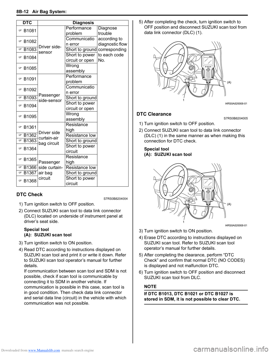
DTC CheckS7RS0B8204004
1) Turn ignition switch to OFF position.
2) Connect SUZUKI scan tool to data link connector (DLC) located on underside of instrument panel at
driver’s seat side.
Special tool
(A): SUZUKI scan tool
3) Turn ignition switch to ON position.
4) Read DTC according to instructions displayed on SUZUKI scan tool and print it or write it down. Refer
to SUZUKI scan tool operator’s manual for further
details.
If communication between scan tool and SDM is not
possible, check if scan tool is communicable by
connecting it to SDM in another vehicle. If
communication is possible in this case, scan tool is
in good condition. Then check data link connector
and serial data line (circuit) in the vehicle with which
communication was not possible. 5) After completing the check,
turn ignition switch to
OFF position and disconnect SUZUKI scan tool from
data link connector (DLC) (1).
DTC ClearanceS7RS0B8204005
1) Turn ignition switch to OFF position.
2) Connect SUZUKI scan tool to data link connector (DLC) (1) in the same manner as when making this
connection for DTC check.
Special tool
(A): SUZUKI scan tool
3) Turn ignition switch to ON position.
4) Erase DTC according to instructions displayed on
SUZUKI scan tool. Refer to SUZUKI scan tool
operator’s manual for further details.
5) After completing the clearance, perform “DTC Check” and confirm that normal DTC (NO CODES)
is displayed and not malfunction DTC.
6) Turn ignition switch to OFF position and disconnect SUZUKI scan tool from DLC.
NOTE
If DTC B1013, DTC B1 021 or DTC B1027 is
stored in SDM, it is not possible to clear DTC.
�) B1081
Driver side-
sensor Performance
problem
Diagnose
trouble
according to
diagnostic flow
corresponding
to each code
No.
�)
B1082 Communicatio
n error
�) B1083 Short to ground
�) B1084 Short to power
circuit or open
�) B1085 Wrong
assembly
�) B1091
Passenger
side-sensor Performance
problem
�) B1092 Communicatio
n error
�) B1093 Short to ground
�) B1094 Short to power
circuit or open
�) B1095 Wrong
assembly
�) B1361
Driver side
curtain-air
bag circuit Resistance
high
�) B1362 Resistance low
�) B1363 Short to ground
�) B1364 Short to power
circuit
�) B1365
Passenger
side curtain-
air bag
circuit Resistance
high
�) B1366 Resistance low
�) B1367 Short to ground
�) B1368 Short to power
circuit
DTC Diagnosis
1
(A)I4RS0A820008-01
1(A)I4RS0A820008-01
Page 1052 of 1496
Downloaded from www.Manualslib.com manuals search engine 8B-14 Air Bag System:
CAUTION!
• Be sure to perform “Air Bag Diagnostic System Check” before starting diagnosis according to flow.
• When measurement of resistance or voltage is required in this flow, use a tester along with a correct terminal adapter from special tool (Connector test adapter kit).
• When a check for proper connection is required, refer to “Inspection of Intermittent and Poor Connections”.
• If there is open circuit in the air bag wire harnes s, connector or terminal is found damaged, replace
the wire harness, connector and terminal as an assembly.
Flow Test Description
Step 1: Check for “A/BAG” fuse blown.
Step 2, 3: Check for loose connection between junction block assembly connector and junction block
assembly.
Step 4: Check for loose connection between SDM connector and SDM.
Step 5: Check for SDM power supply circuit.
Step 6: Check for short circuit between “A IR BAG” warning right circuit and ground.
Troubleshooting Step Action YesNo
1 1) Turn ignition switch OFF.
2) Remove and inspect “A/BAG” fuse.
Is fuse good? Go to Step 2.
“RED” wire short to
ground.
After repair, replace “A/
BAG” fuse.
2 1) Check for loose connection of junction block assembly connector “L04”.
Is it connected securely? Go to Step 3.
Correct connector “L04”
securely.
3 1) Check for loose connection of junction block assembly connector “G34”.
Is it connected securely? Go to Step 4.
Correct connector “G34”
securely.
4 1) Check for loose connection of SDM connector “L29”. Is it connected securely? Go to Step 5.
Correct connector “L29”
securely.
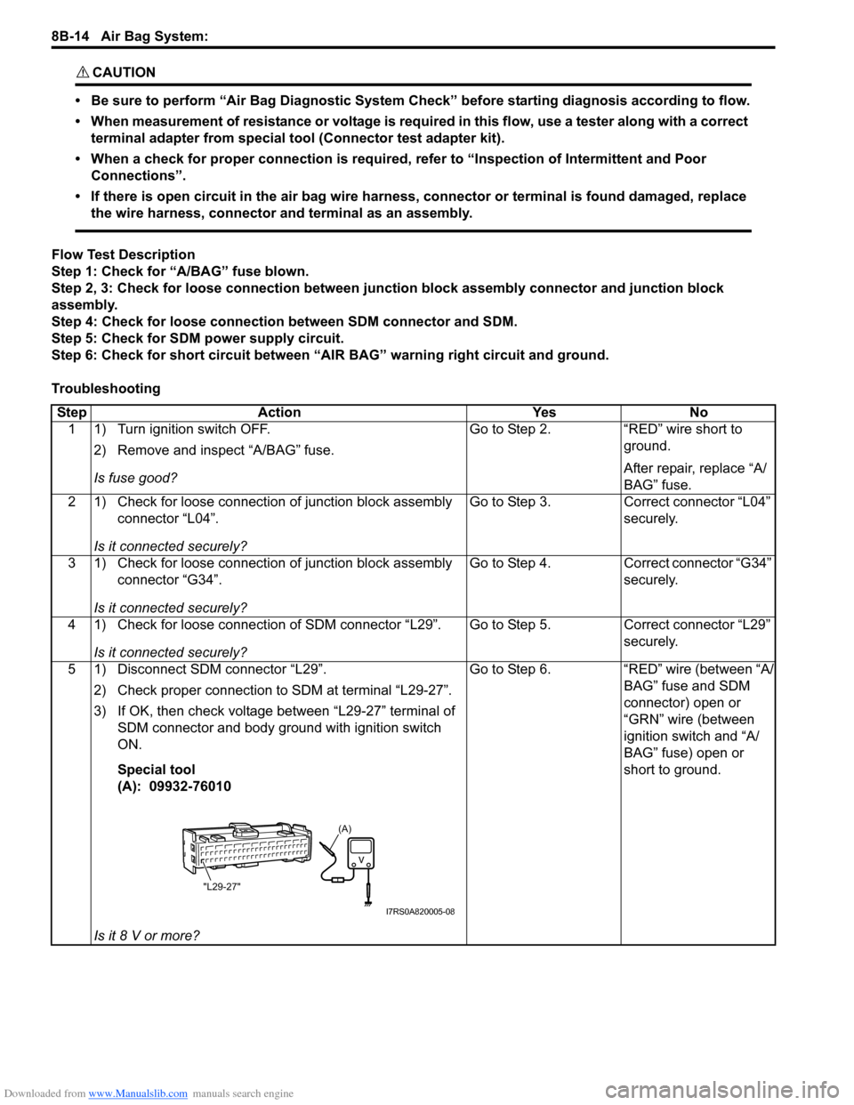
5 1) Disconnect SDM connector “L29”. 2) Check proper connection to SDM at terminal “L29-27”.
3) If OK, then check voltage between “L29-27” terminal of SDM connector and body ground with ignition switch
ON.
Special tool
(A): 09932-76010
Is it 8 V or more? Go to Step 6.
“RED” wire (between “A/
BAG” fuse and SDM
connector) open or
“GRN” wire (between
ignition switch and “A/
BAG” fuse) open or
short to ground.
(A)
"L29-27"
I7RS0A820005-08
Page 1053 of 1496
Downloaded from www.Manualslib.com manuals search engine Air Bag System: 8B-15
NOTE
Upon completion of inspection and repair work, perform the following items.
• Reconnect all air bag system components and ensure all components are properly mounted.
• Repeat “Air Bag Diagnostic System Check” to confirm that the trouble has been corrected.
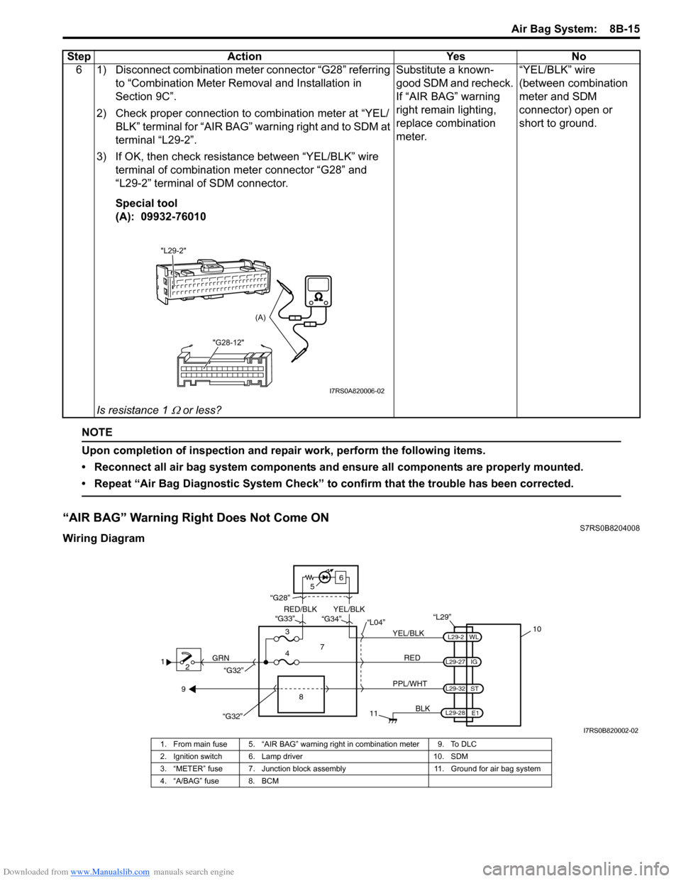
“AIR BAG” Warning Right Does Not Come ONS7RS0B8204008
Wiring Diagram6 1) Disconnect combination meter connector “G28” referring
to “Combination Meter Removal and Installation in
Section 9C”.
2) Check proper connection to combination meter at “YEL/ BLK” terminal for “AIR BAG” warning right and to SDM at
terminal “L29-2”.
3) If OK, then check resistance between “YEL/BLK” wire terminal of combination meter connector “G28” and
“L29-2” terminal of SDM connector.
Special tool
(A): 09932-76010
Is resistance 1
Ω or less? Substitute a known-
good SDM and recheck.
If “AIR BAG” warning
right remain lighting,
replace combination
meter.
“YEL/BLK” wire
(between combination
meter and SDM
connector) open or
short to ground.
Step Action Yes No
"L29-2"
"G28-12"
(A)
I7RS0A820006-02
12 GRN
11
BLK
L29-27
L29-2
L29-28 WL
E1
IG
L29-32
ST
10
8
“L29”
RED
PPL/WHT
7
3
4 “L04”
“G34”
“G33”
“G28”
“G32”
5 6
“G32”
YEL/BLK
YEL/BLK
RED/BLK
9
I7RS0B820002-02
1. From main fuse 5. “AIR BAG” warning right in combination meter 9. To DLC
2. Ignition switch 6. Lamp driver 10. SDM
3. “METER” fuse 7. Junction block assembly 11. Ground for air bag system
4. “A/BAG” fuse 8. BCM
Page 1054 of 1496
Downloaded from www.Manualslib.com manuals search engine 8B-16 Air Bag System:
CAUTION!
• Be sure to perform “Air Bag Diagnostic System Check” before starting diagnosis according to flow.
• When measurement of resistance or voltage is required in this flow, use a tester along with a correct terminal adapter from special tool (Connector test adapter kit).
• When a check for proper connection is required, refer to “Inspection of Intermittent and Poor Connections”.
• If there is open circuit in the air bag wire harnes s, connector or terminal is found damaged, replace
the wire harness, connector and terminal as an assembly.
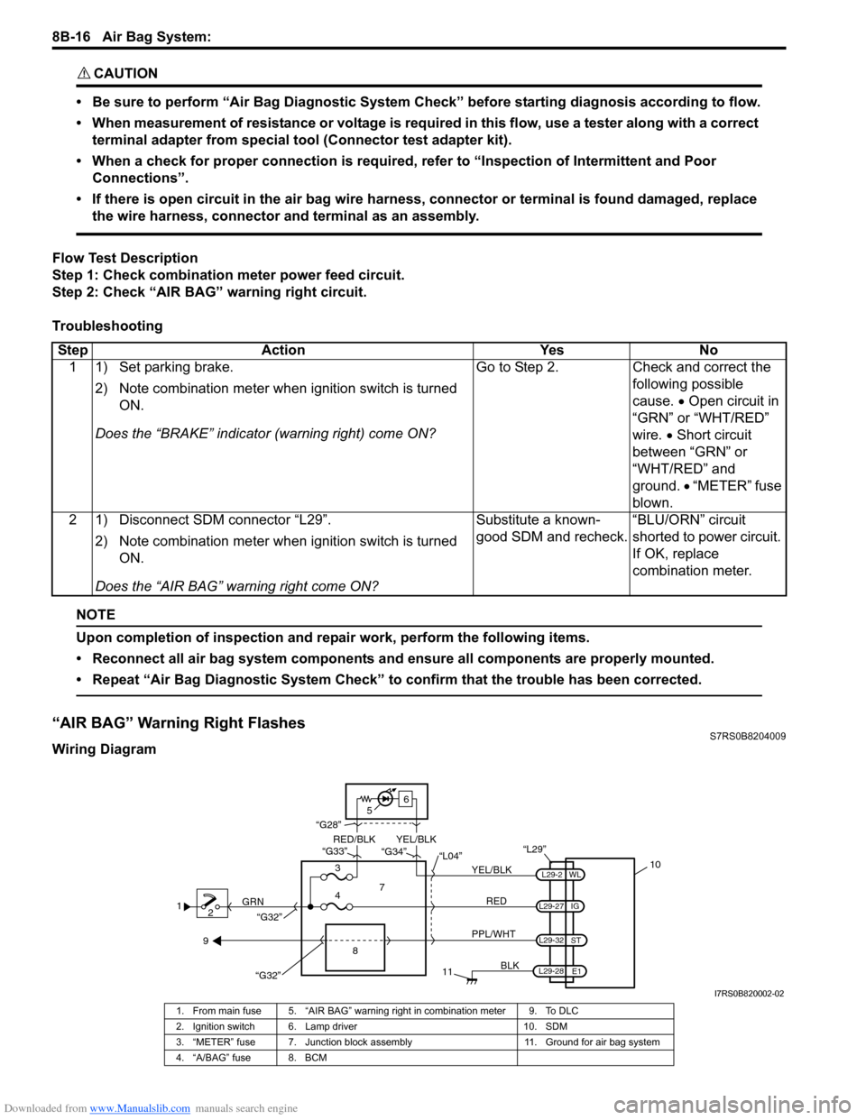
Flow Test Description
Step 1: Check combination meter power feed circuit.
Step 2: Check “AIR BAG” warning right circuit.
Troubleshooting
NOTE
Upon completion of inspection and repair work, perform the following items.
• Reconnect all air bag system components and ensure all components are properly mounted.
• Repeat “Air Bag Diagnostic System Check” to confirm that the trouble has been corrected.
“AIR BAG” Warning Right FlashesS7RS0B8204009
Wiring Diagram Step Action Yes No
1 1) Set parking brake.
2) Note combination me ter when ignition switch is turned
ON.
Does the “BRAKE” in dicator (warning right) come ON? Go to Step 2. Check and correct the
following possible
cause. • Open circuit in
“GRN” or “WHT/RED”
wire. • Short circuit
between “GRN” or
“WHT/RED” and
ground. • “METER” fuse
blown.
2 1) Disconnect SDM connector “L29”.
2) Note combination me ter when ignition switch is turned
ON.
Does the “AIR BAG” warning right come ON? Substitute a known-
good SDM and recheck.
“BLU/ORN” circuit
shorted to power circuit.
If OK, replace
combination meter.
1
2 GRN
11
BLK
L29-27
L29-2
L29-28 WL
E1
IG
L29-32
ST
10
8
“L29”
RED
PPL/WHT
7
3
4 “L04”
“G34”
“G33”
“G28”
“G32”
5 6
“G32”
YEL/BLK
YEL/BLK
RED/BLK
9
I7RS0B820002-02
1. From main fuse 5. “AIR BAG” warning right in combination meter 9. To DLC
2. Ignition switch 6. Lamp driver 10. SDM
3. “METER” fuse 7. Junction block assembly 11. Ground for air bag system
4. “A/BAG” fuse 8. BCM
Page 1055 of 1496
Downloaded from www.Manualslib.com manuals search engine Air Bag System: 8B-17
CAUTION!
• Be sure to perform “Air Bag Diagnostic System Check” before starting diagnosis according to flow.
• When measurement of resistance or voltage is required in this flow, use a tester along with a correct terminal adapter from special tool (Connector test adapter kit).
• When a check for proper connection is required, refer to “Inspection of Intermittent and Poor Connections”.
• If there is open circuit in the air bag wire harnes s, connector or terminal is found damaged, replace
the wire harness, connector and terminal as an assembly.
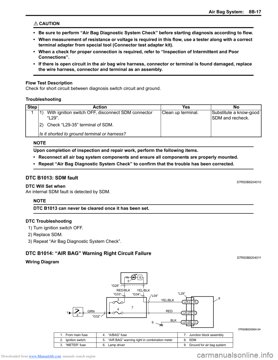
Flow Test Description
Check for short circuit between diag nosis switch circuit and ground.
Troubleshooting
NOTE
Upon completion of inspection and repair work, perform the following items.
• Reconnect all air bag system components and ensure all components are properly mounted.
• Repeat “Air Bag Diagnostic System Check” to confirm that the trouble has been corrected.
DTC B1013: SDM faultS7RS0B8204010
DTC Will Set when
An internal SDM fault is detected by SDM.
NOTE
DTC B1013 can never be cleared once it has been set.
DTC Troubleshooting 1) Turn ignition switch OFF.
2) Replace SDM.
3) Repeat “Air Bag Diagnostic System Check”.
DTC B1014: “AIR BAG” Warning Right Circuit FailureS7RS0B8204011
Wiring DiagramStep Action Yes No
1 1) With ignition switch OFF, disconnect SDM connector “L29”.
2) Check “L29-35” terminal of SDM.
Is it shorted to ground terminal or harness? Clean up terminal. Substitute a know-good
SDM and recheck.
12 GRN
9
BLK
L29-2
L29-27
L29-28 IG
E1
WL
8
“L29”
RED
7
3
4 “L04”
“G34”
“G33”
“G28”
“G32”
5 6
YEL/BLK
YEL/BLK
RED/BLK
I7RS0B820004-04
1. From main fuse 4. “A/BAG” fuse
7. Junction block assembly
2. Ignition switch 5. “AIR BAG” warning right in combination meter 8. SDM
3. “METER” fuse 6. Lamp driver 9. Ground for air bag system